Wireless Ultrasonic Anemometer and Anemoscope Data-Logger System based on the Web
Copyright © The Korean Society of Marine Engineering
This is an Open Access article distributed under the terms of the Creative Commons Attribution Non-Commercial License (http://creativecommons.org/licenses/by-nc/3.0), which permits unrestricted non-commercial use, distribution, and reproduction in any medium, provided the original work is properly cited.
Abstract
Recently, the international standard RS-422 serial communication, which was primarily designed for the communications between micro-controllers, has been used as a communication method on the ship. However, as the NMEA (National Marine Electronics Association) 2000 standardization progresses recently, a high-speed Ethernet-based communication environment is expected to be an alternative communication method instead of the RS-422 gradually. In addition, the ship's main instrumentation equipment with versatility and convenience is implemented to control devices as monitoring and controlling tools. This paper describes an implementation of wireless ultrasonic anemometer and anemoscope data processing and logger system using PC network, where the control processing equipment such as a separate operational console, data-logger, and indicator is required for the system. For these, the related element technologies to implement ultrasonic anemometer and anemoscope data processing system are expressed as a functional modules, and the NMEA 2000 standard certified data-logger system is implemented without the separate operational console.
Keywords:
NMEA2000, Ultrasonic anemometer, Anemoscope, Data-logger, Indicator1. Introduction
Since NMEA 0183 standard was established by the IEC (International Electro-technical Commission) as IEC61162-1, so far, it has been used on most ships. However, recent ship and logistics automation have been making ship operations much more complicated, and ship communication equipment and system are also getting more complex. Especially, the ship telecommunication equipment lately released is required to develop devices, featuring a high data transmission rate and wide band signal transmission. Ultrasonic Anemometer, an essential device equipped on a ship by the regulation of ISO, is universally utilized not only for a weather observation, atmospheric diffusion observation, environmental analysis, safety supervision and maritime application field, but also for a land, marine, and wind power plant. The importance of using an ultrasonic Anemometer has been significantly getting raised. Over 80 percent types of anemometer and anemoscope utilized in South Korea is a mechanical and electric type device [1][2].
Lately, wind power, moreover, is getting popular as a green renewable energy source. And weather prediction estimated of wind direction and velocity is getting much more important since it can play a significant role to prevent climate disasters – such as Tsunami, Rain spell, etc. – causing massive damage and devastation. Rising the importance of weather prediction, the utilization of the more accurate ultrasonic anemometer is getting rapidly required. In general, Anemometer & Anemoscope are devices installed at the top position of a mast and wind plant. To manage these devices, a test procedure shall be firstly preceded on a high position, in which they are located and equipped, with a separate console box, data logger and indicator that shall be transported up to the location devices equipped. And firmware and data updating shall be processed through the same way. As described above, its maintenance is an extremely difficult task that extra manpower required.
In this paper, hence, it is advised how to implement a data logger in order to monitor the condition of the equipment by managing an element technology. A system is designed to reduce the maintenance cost of the data processing system of † UA&A and to execute a web based database processing system so a computer is employed to implement the function of a data logger and indicator without a separate operational console in NMEA 2000 standard by a technical function coded to execute an element technology fulfilling a data processing system of UA&A.
2. Related Works
2.1 Ultrasonic Anemometer Indicating System
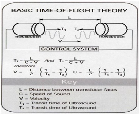
The Ultrasonic Wind Anemometer is an electric device equipped with an advanced feature, not forming mechanical abrasion, which is one of significant defects of a type of a mechanical wind anemometer occurred from using a Syncro and Resolver. It features high speed and accuracy for measurements because it can measure the purse transmission time between fixed ultrasonic sensors. The ultrasonic sensor runs to help compute the distance measured by the elapsed time that an ultrasonic echo vibrated from the vibrator of the piezoelectric transmitter reaches to the receiver. For Figure 1, it presents the generation and detection of the ultrasonic wave. The wind velocity can be calculated by computing the elapsed time of the ultrasonic transmitted and received between two sensors and measuring the sonic vector by use of the pulse transmission difference formed between the two fixed ultrasonic transducers [3].
2.2 Theory of Ultrasonic Anemometer
The Ultrasonic anemometer using TOF (Time of Flight) measures the difference between transmission as shown in Figure 2 and reception wave, instead of detecting the envelope of receiving pulse train, repeating to operate the transmission and reception sensors, placed facing to each other.
In this mode, especially, it is detected the envelope of the pulse train and measured the traveling time from the peak point. Therefore, it is capable to measure the wind velocity once from each transmission pulse train. In a certain ultrasonic sensor, for compensation of the variation of the sound velocity in the atmospheric condition, two pairs of ultrasonic sensor are employed to send the pulse train ultrasonic wave of the opposite direction to each other. In general, the TOF measuring method is to transmit 50-100 times of 5-10 pulse signals in one second and to measure the traveling time of the pulse signals reaching to the reception sensor. Especially, early signals are generally corrected and sent to the indicator and the data logger device through signal communication RS-232, 422, 485 because an ultrasonic sensor shall consider the distance and phase difference of two sensor transducers.
2.3 Data-Logger Communication Processor
Heretofore, an Ultrasonic Wind Anemometer has complied with NMEA 0183 for a measuring instrument control. RS-422 has been used more than RS-232 since it features the long range communication exceeded 1km and 10Mb/s over the binary rate. As shown in Table 1, in comparison with RS-422, RS-232 features the short serial communication distance and slow communication speed. In general, RS-232 com port isn’t equipped with the PC therefore RS-232 to 422 convertor, USB to RS-422 convertor, RS-422 PCI card shall be installed in order to conduct the data communication.
NMEA0183 standard is for a simplex communication that supports 1: 1 serial communication between a taker and listener and RS-422 standard is generally employed for a talker. For a listener, DC insulation is required a photo-coupler to protect a circuit and help the reception of data from surge voltage, voltage difference of devices and noise [4].
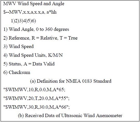
ASCII code, 0x0D (CR) and 0x0A (LF), is employed and the type of data format is utilized from 0x20 to 0x7E. All sentences start to be written with “$” or “!” and ended up with CR/LF. The minimum length of a sentence is 14bytes and the maximum length is 82 bytes. A checksum, at the end of a sentence, plays a role to distinguish data fields by entering of “*”, and 4800 bps, 8bit, no parity and 1 stop bit are used. As shown in Figure 3, WI represents for Weather Instrument as an identifier for a talker according to MNEA 0183standard. In Figure 3 (a), Wireless Ultrasonic Anemometer & Anemoscope Data-Logger System is the wind direction, 0.0 is velocity and M is the unit of wind velocity.
3. Implementation of Ultrasonic Wind Data-Logger System based on the Web
3.1 Design of data-logger based on the Web
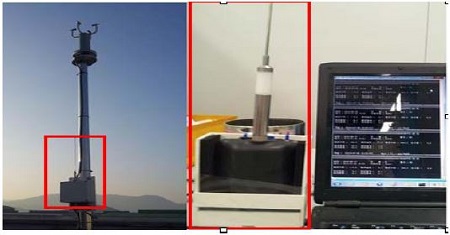
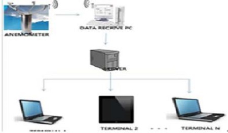
In this research, test-bed is to be organized for the 16 bit Micom control of an ultrasonic wind anemometer, and a microprocessor is connected as a serial communication to exchange external information via peripheral devices, as shown in Figure 4.
A serial communication is designed to use of an external communication. It can be used on the LAN, RS-232 and classified as a synchronous and asynchronous type. It can also save the cost using for communication. An asynchronous signal, come out from UART (Universal Asynchronous Receiver Transmitter) – a communication controller, is the level of TTL signal, which is weak from a noise and restrict of a communication distance.
A synchronous signal is strong against the noise since TTL signal is entered on it. IC, an interface transmitting a signal to the long distance, is named “Line Driver/Receiver” and typical types of this are RS-422 and RS-485. RS-422 – a serial network communication method being used by ISO in 1993 and designed for the microcontroller’s communication organized for the control – is utilized for an inner communication of an ultrasonic wind anemometer. RS422 or RS232C convertor is employed to convert the signal to control PC-network and RS232C are converted to TCP/IP protocol.
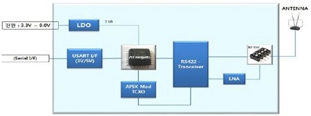
NMEA signal generated from an ultrasonic wind anemometer via RF wireless module used ISM (Industrial Science and Medical) is transmitted to the data receiver PC. For the radio transmission, 600 Hz is chosen to use as a square wave is high as shown in Figure 5. As it is low a sinusoidal wave of 1200 Hz is used to transmit RF modulated of AFSK. In RF wireless module configuration, 3.3V-9.0V (Low-Dropout Regulator) is a voltage of the main power and MCU is used of ATmega8L, operated by a low power. RS-422 RF transceiver is equipped and UART communication is for 3V and 5V. Low-noise amplifier and RF switch are equipped.
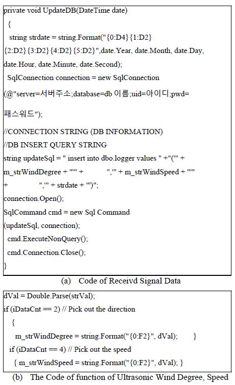
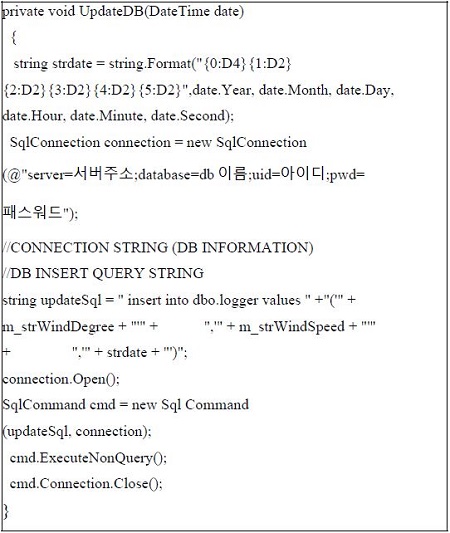
RS-422 is most used in an ultrasonic wind anemometer system, and Atmega an AVR microprocessor controlling of RS- 422, converts a UART signal to RS-422 signal transmitting for the PC. RS-422 to RS-232C convertor is used on the PC converting a RS-422 signal of the ultrasonic wind anemometer to RS-232C signal to receive data. As shown in Figure 6 (a) and Figure 6 (b), needed data value of the wind direction and velocity is adjusted .
1) Implementation of Data-Logger Based Web HTML5
After abstracting data, the following function is used to save data. As shown in Figure 7, to design the layout of the ultrasonic wind anemometer data logger implements the arrow mark of the wind direction by the HTML5 canvas. The asynchronous communication is implemented by the AJAX to enhance the response speed, and the screen blinking in every one second whenever it gets refreshed.
2) Function Demonstrating a Wind Direction
This function is designed to operate visually displaying the wind direction data value, received from the database, in the degree of 5 apart. As shown in Figure 8, the data gets updated in real time through the function, interworked with the database, outputting the information regularly.
3) Real-Time C/S Wind Direction and Velocity Data Processing System
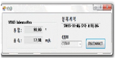
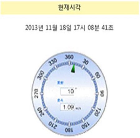
As shown in Figure 8, the function, capable to display the output of the real time wind velocity and direction received from the database, has been implemented. As shown in Figure 9, it shows how the function operates to display the wind direction and velocity as it is normally searched from the server. While an error message shows up on the screen in the abnormal case. The current time is displayed on the upper side of the screen to implement to immediately get knowing the current wind direction and velocity. It is implemented to operate the synchronization by the GMT (Greenwich Mean Time), as a standard, after interlocking with the timer in the PC.
4. Result of Ultrasonic Anemometer & Anemoscope Data-Logger based on the Web
Wireless signals in the indoor environment include noises because they are easily distorted by various disturbances such as spatial structure, quality of the material, and electronic equipment and the range errors can be reduced by using several filters. Reduction of range errors is a very important process for accurate estimation of the locations of objects, which is the main objective of the indoor localization.
To display and process the wind velocity and direction data received from the server to the PC, it was designed the synchronized display, based on the electrical type indicator as shown in Figure 9 and Figure 10.
According to the NMEA 2000 standardization, in this paper, RS-232/422/485 – currently used and equipped on the ship – has been researched to develop the web based control system using the PC. The developed control system controls the data processing device interlocked with the sensor and, without the separate module, makes it possible to verify the displayed indicator by the single client. Through the communication module of the ultrasonic wind anemometer, a device used in the poor environment, the system of each signal conditioner can be tested in real time. In conclusion, it is anticipated the implemented control system will be getting widely employed for NMEA 0183/2000, and other systems – properly supporting the radio communication – and applied to other measuring instrument.
Acknowledgments
Ultrasonic anemometers have become available for precise, high-frequency measurement of three dimensional velocity and turbulence properties. This papers Referenced about Ultrasonic Wind Theory (TOF) and ultrasonic speed, angle measure activity process treatment.
This paper is extended and updated from the short version that appeared in the Proceedings of the International Symposium on Marine Engineering and Technology (ISMT 2014), held at BEXCO, Busan, Korea on October 17-19, 2014.
References
- J. T. Hong, D. H. Park, and Y. H. Yu, “A study of NMEA 2000 protocol application for ship electrical power converter monitoring system,”, Journal of Korean Society of Mechanical Engineers, 13(2), p288-294, (201), (in Korean).
-
D. K. Lee, and S. S. Yhim, “Estimation of wind resistance capacity of nielsen arch bridge based on measured data from monitoring system,”, Journal of the Korea Institute for Structure Maintenance and Inspection, 17(3), p56-64, (2013), (in Korean).
[https://doi.org/10.11112/jksmi.2013.17.3.056]

-
S. G. Lee, Y. S. Moon, and S. Y. Cho, “The ultrasonic type wind sensor with piezoelectric actuator,”, Journal of Sensor Science and Technology, 22(4), p292-296, (2013).
[https://doi.org/10.5369/JSST.2013.22.4.292]

- J. H. Kim, A Study on the Development of a Sonic Anemometer Loaded with NMEA 2000, M.S. Thesis, Department of Control and Measurement Engineering, Korea Maritime and Ocean University, (2011), (in Korean).

