LiDAR-based background interpolation method for obstacles
Copyright © The Korean Society of Marine Engineering
This is an Open Access article distributed under the terms of the Creative Commons Attribution Non-Commercial License (http://creativecommons.org/licenses/by-nc/3.0), which permits unrestricted non-commercial use, distribution, and reproduction in any medium, provided the original work is properly cited.
Abstract
LiDAR is a crucial element of location-based services (LBSs), including autonomous driving, and is a technology that can identify surrounding objects and terrain. The topography changes due to the occlusion at the indoor where the movement of objects is frequent limits positioning using LiDAR. We propose the dual-background segmentation model, which can distinguish terrain and remove obstacles, and the Binning-based Mode Interpolation Algorithm, which can interpolate the removed obstacles into the background, is combined in LiDAR-based Background Interpolation Method for Obstacles. The proposed model recognizes an obstacle as an object using a detection model, locates the object, and expresses its shape. Thus, an object is detected in the LiDAR image, and the information of the corresponding ROI is removed. Then, using the binning-based mode interpolation algorithm, the background of the obstacle is restored by interpolating the remaining area based on depth information from the surrounding terrain of the object. Thus, the proposed method can acquire the topography even in an indoor space with many object changes.
Keywords:
Light detection and ranging, Background interpolation, Object detection1. Introduction
Recently, the utilization of self-driving devices such as drones and robots has increased in everyday life. For instance, robots must recognize their surroundings, avoid obstacles, and provide targeted services similar to humans who visually grasp the surrounding terrain. These robots are equipped with various sensors for this function, such as cameras, radars, and LiDARs.
Cameras are intuitive and contain vast amounts of information because they perceive the world similar to humans. However, they have limitations in terms of individual computations because individual robots process them. radars, which have been developed for ships and aircraft, have broader coverage than other sensors and are technologically advanced. However, they encounter difficulties in recognizing the detailed terrain.
LiDAR, which employs the difference in the arrival time of the receiving and sending ends using light, can simultaneously derive the relative distance of surrounding objects. Compared with radar, LiDAR has limited coverage because of the straightness of light, but its resolution is higher. Owing to this advantage, the most recent self-driving solutions are equipped with LiDAR.
Terrain analysis using LiDAR is a widely utilized method in aviation owing to its ability to analyze environments without obstacles. However, when robots or drones are deployed on the ground, many moving objects exist, including humans. These objects are superimposed on the terrain already recognized through SLAM, making it challenging to accurately determine the exact location. Furthermore, LiDAR cannot distinguish between objects and the terrain, thus making it impossible to interact with objects. Consequently, a separate sensor or communication system is necessary [1]. Even a 2D LiDAR in the form of an image has only a single distance channel, making it challenging to distinguish between objects and the terrain. To address these limitations, researchers have combined LiDAR with cameras to reconstruct 3D objects recognized by the cameras using LiDAR [2]. Nevertheless, this approach has the limitation of requiring a separate camera, making it challenging to apply to relatively low-cost robots because the images must be processed simultaneously.
In a recent study by Li [3], object recognition using LiDAR was achieved by directly applying a Faster RCNN to LiDAR data. However, owing to the recognition of objects in a 3D scan environment, applying this study to the LiDAR technology used in general driving robots is challenging. Moreover, because these studies recognize only the presence of objects, their applicability is limited. A typical mobile robot operates in a complex environment in which humans and objects coexist indoors, necessitating the distinction of objects and further recognition of the terrain. However, existing studies focus only on object recognition and do not recognize the topographical characteristics of the area where objects disappear.
This study proposes a LiDAR-based approach that addresses the challenge of recognizing and distinguishing between terrain and obstacles in complex environments. Specifically, we introduce a dual-background segmentation model and a binningbased mode interpolation algorithm that work together to remove obstacles and interpolate the resulting background. The proposed interpolation method for obstacles comprises two components: a dual-background segmentation algorithm that detects and removes objects from LiDAR images by applying an object recognition model and a binning-based mode Interpolation algorithm that fills the areas left behind by the removed objects using depth information from the surrounding terrain. The dual-background segmentation model identifies obstacles as objects by applying an object recognition model, locates the objects, and represents them as polygons using contour information. The corresponding region of interest is then removed from the LiDAR image. The remaining areas are interpolated using a binning-based mode interpolation algorithm to restore the original background. The proposed method can quickly acquire topographical information in complex indoor spaces, where many objects obstruct LiDAR sensing. In summary, the proposed method provides a solution to the challenge of recognizing and distinguishing obstacles and terrain in complex environments using LiDAR technology.
2. Related background
2.1 Faster regional-CNN (Faster R-CNN)
Since its introduction, Faster R-CNN [4] has been widely used as a universal object detection model owing to its improvements over previous models such as R-CNN [5] and Fast R-CNN [6]. Numerous studies have been conducted to enhance various model components. However, because of its intuitive model architecture, it remains the mainstream choice for many computer vision tasks, including object tracking [7][8], image captioning [9][10], OCR [11]-[13], and object detection. Faster R-CNN addresses variations in object size by generating candidate regions for objects of various sizes using regional proposal networks (RPNs). First, the model extracts feature from an image using a CNN-based backbone. Then, the RPN uses the sliding window technique to identify areas in the input image that could contain the target object. The feature vector size is standardized through ROI pooling in the detected region, and object detection is performed by learning the object type and location via classifier layers.
2.2 Light detection and ranging (LiDAR)
LiDAR, a sensing system that employs light to determine the distance and location of objects, differs from radar, which utilizes radio waves. This technology utilizes the time of flight (ToF), a method that calculates the time required for light to reflect and return to a target, to determine the target information. ToF measures the time required for the light emitted from the transmitter to reach the target and return to the receiver to determine the characteristics of the target. Whereas LiDAR has a narrower coverage area than radar because of the direct nature of light, it is frequently employed in indoor environments, such as autonomous driving and surveillance systems, owing to its high precision. In addition, recent research has explored the integration of machine learning techniques with LiDAR to enhance its capabilities in various fields, including object recognition [14][15], object tracking [16][17], and action recognition [18][19], extending beyond its conventional use in terrain modeling [20][21].
3. Proposed interpolation method
3.1 Overview of the proposed interpolation method
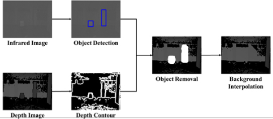
In this study, we propose a LiDAR-based background interpolation method for map generation using infrared-based LiDAR in the presence of obstacles such as people and boxes. The inability to penetrate obstacles owing to the straightness of LiDAR has a significant impact on indoor mapping accuracy. To solve this problem, most mapping applications use LiDAR measurements in the early morning hours after obstacles are removed to measure the structure. However, by limiting the measurement time to the early morning hours, manpower and costs become prohibitive, limiting the mapping of buildings using LiDAR. Therefore, to generate LiDAR maps in indoor environments with frequent obstacle movement, the dual-background segmentation model and the binning-based mode interpolation algorithm are applied to detect and remove obstacles as objects and interpolate the object information with the surrounding depth information. Figure 1 demonstrates a block diagram of the proposed method.
3.2 Dual-background segmentation model
To remove an obstacle, identifying the location and shape of an object is more important than its classification. The proposed dual-background segmentation model comprises an object recognition model and an object contour algorithm. Commonly used object recognition models, the YOLO and R-CNN series, are trained on three-channel images. However, they cannot be applied to infrared-based LiDAR images that are one-channel images. Therefore, learning difficulty and speed should be considered. R-CNN is slow in recognizing objects in real time. However, it has high accuracy. In an object recognition model that uses infrared images as input, infrared images have fewer channels than normal images; therefore they have low accuracy rather than high speed. Therefore, in this study, we use infrared images to identify the location of objects using a faster R-CNN-based object recognition model.
After the object is removed, the background interpolation method can be implemented by changing the depth information of the bounding box resulting from the object recognition to the depth information of the surrounding terrain. However, when the depth information of the surrounding terrain varies, interpolating to the background is difficult. Therefore, the proposed object removal model does not remove objects in the form of a simple box but removes objects in the form of a polygon shaped like an object to improve the accuracy of background interpolation by utilizing the surrounding background as much as possible.
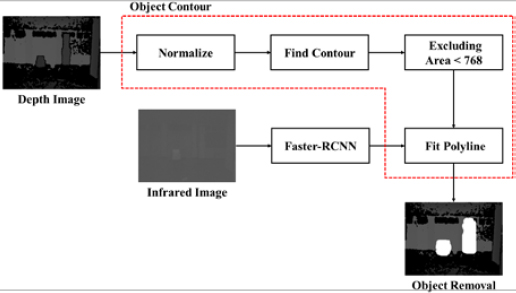
Figure 2 shows the architecture of the proposed object removal model. Depth images of the structure of an indoor building captured with a LiDAR camera have clear boundaries, unlike typical images captured with a regular camera. Because of this characteristic, we can proceed with preprocessing by normalization, which has a high computational speed, instead of using a heavy preprocessing algorithm such as Canny that detects the boundary lines of the image in contour detection to construct a polygon. After preprocessing, a contour algorithm is used to detect the outlines of the walls and objects in the image. However, because of the noise generated by the LiDAR camera, small contours that are not objects are detected, and the area of the contour removes these small contours. Noise-induced contours are removed by removing the contours whose area does not exceed 768; this is 1% of the total image area. Consequently, only the outlines of the walls and objects are detected, and the object outlines are used to represent them as polygons. For this purpose, only the outlines containing the location of the object derived from object recognition are extracted and converted into polygons for object removal using a polyline. The object information is covered by a polygon and removed.
3.3 Binning-based mode interpolation algorithm
Obstacles that are removed as polygons should be replaced with background information. However, LiDAR is highly linear and cannot detect obstacle backgrounds. Therefore, obstacle information must be replaced by interpolating the background around the obstacle. Indoor depth images typically capture walls and hallways. This causes sharp changes in the values at their boundaries. Therefore, applying linear and bilinear interpolations, which interpolate the empty information in the image using weights according to the distance from the known information, is difficult. Therefore, in this study, background interpolation is performed using a binning-based mode interpolation algorithm.
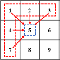
The proposed algorithm interpolates the values of the five regions using the region values of 1, 2, 3, 4, and 7 in a 3 × 3 mask, as shown in Figure 3. Because the depth image contains noise, to remove noise of the depth information, the bins of the depth information are categorized into 10 bins to obtain the frequency count. Among the 10 nonzero bins, the bins with the highest frequency count and the next most frequency count are sorted; these are defined as rank1 and rank2, respectively.
We use rank1 and rank2 to determine the dominant background. This is derived as follows:
| (1) |
Here, xn represents the value of the surrounding background and is a set of five regions, 1,2,3,4, and 7, as shown in Figure 3. A polygon represents the value of an object removed by the previous algorithm. The count function is a frequency counting function. It counts the number of times the five region values satisfy each condition. Set X computes the interpolation region using
| (2) |
Here, the mode function determines the area corresponding to the condition with the highest frequency in each condition. This is interpolated by determining the average value for each region using the avg function. Using Equations (1) and (2), we can organize the values of the regions into bins that can be used to determine the dominant information in the background. Because this method interpolates the dominant information in the surrounding background, the proposed algorithm can be used not only when the interpolation location has continuous information, such as a wall, but also when the interpolation location is a boundary plane, if the object is not completely obscured by the background.
4. Experiment and results
4.1 Experimental environment
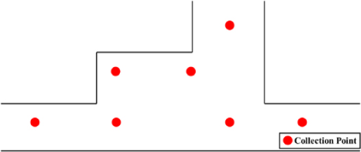
In this study, an Intel RealSense LiDAR camera L515 was installed on a tripod to collect images, and the entire process was developed using Python. To collect images in an indoor environment, a corridor in front of Room 333 on the third floor of Building 1, College of Engineering, Korea Maritime University, was set up as the experimental environment. Figure 4 shows the structure of the experimental environment and shooting points. We used a LiDAR camera with a maximum range of 9 m; therefore, we set it at a point where there was a background within a 9 m radius. Here, the images were captured in four directions centered on the shooting point, and sections with only corridors and glass sections where data collection was not possible were removed. In the experiment, boxes, people, and chairs were used as obstacles and all points were first recorded without obstacles to collect the GT. Images were then collected in the presence of a box, chair, or person to simulate an obstacle scenario.
The images captured by the LiDAR camera were labeled using labeling tool LabelImg. Unlike general object recognition, the object recognition model in this study only identifies the location of the object. Therefore, we specified the class as an object and focused on labeling its coordinates. The FPS of the LiDAR camera was 30, and sampling was performed every 30 s. The total number of collected data points was 750, excluding the GT, and the ratio of training to testing was 9:1.
4.2 Evaluation of object detection performance
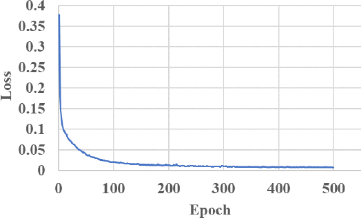
The object recognition model uses a Faster R-CNN. The training image was an infrared image captured by LiDAR and converted into grayscale to train the model. Figure 5 shows the loss graph of the Faster R-CNN trained with infrared images, where the x-axis represents the number of iterations, and the y-axis represents the loss. Notably, the loss converged after 200 epochs.
To check the performance of the object recognition model, we used mean average precision (mAP) as an evaluation metric. The mAP was obtained by averaging the area values of the precision-recall graph for each class. The higher the value of mAP, the better the performance. We set the thresholds for the intersection of union (IOU) that identifies the overlapping regions of the GT and predicted bounding box to 0.3, 0.4, 0.5, 0.6, and 0.7.
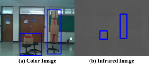
Table 1 lists the mAP when an infrared image is used as the input to a Faster-RCNN. We could check whether an object was correctly detected by the mAP. Notably, the mAP performance of Faster-RCNN was 95.18%, which is high, and the object in the infrared image was correctly recognized. Figure 6 shows the object recognition results, where (a) is a normal image and (b) is an infrared image.
4.3 Evaluation of LiDAR-based background interpolation method performance
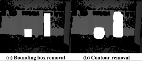
Objects can be removed by changing the ROI value. Figure 7 shows the results of object removal, where (a) the bounding box information is changed, and (b) the information is changed by deriving a polygon of the object shape. The image value changed to 65,535; this was the maximum value of the data type that could not be measured using the LiDAR camera.
The binning-based mode interpolation algorithm was applied to interpolate a value of 65,535, which is the value obtained by removing objects from the image, as background information. To apply the algorithm, the polygon was set to 65,535, which is the image value, based on Equations (1) and (2), the bin was divided into 10 bins by the image histogram, and the frequency was determined; rank1 and rank2 were set to 13,107 and 6,553, respectively. We obtained and applied the binning-based mode interpolation algorithm to interpolate all information in the object-removed image to the background. To evaluate the performance of background interpolation, we compared the proposed method with the bounding box interpolation method that removed and interpolated with a bounding box. For a quantitative evaluation, we checked the peak signal-to-noise ratio (PSNR) and structural similarity index map (SSIM) that were used as image quality metrics. PSNR and SSIM can be used to evaluate the degree of image loss when the image quality changes and can be used to confirm the equivalence between two images. However, in the case of depth images, the quality metrics are not comparable to those of general images because the quality metrics are very poor owing to the LiDAR noise. Therefore, we checked the quality metrics when measuring the same space.
Table 2 compares the PSNR and SSIM of the proposed method and bounding box interpolation method to verify the background interpolation performance. The PSNR and SSIM of the proposed method were 20.43 dB and 0.61, respectively. The PSNR and SSIM of the bounding box interpolation method were 19.68 dB and 0.57, respectively. This showed that the performance of the proposed method improved by 3.81% and 7.02%, respectively. Because the PSNR and SSIM of the GT were 24.80 dB and 0.77, respectively, notably, the PSNR and SSIM of the proposed algorithm reduced by 17.62% and 20.78%, respectively. These results were due to the fact that the data and GT acquisition locations were not exactly the same. This can be solved by perfectly coordinating the acquisition location with the GT.
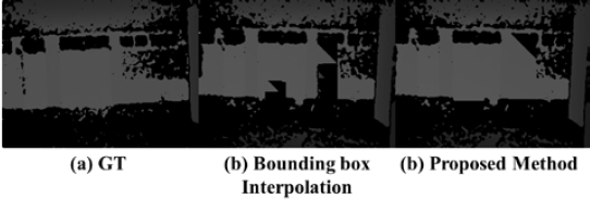
Figure 8 shows the results of the interpolation, where (a) is the GT image, (b) is the resulting image of the bounding box interpolation, and (c) is the resulting image of the proposed method. As shown in Figure 8 (b), the object recognized glass as the dominant background and converted all the information in the object to glass. However, the proposed method distinguished the situation where the glass part was dominant from the situation where the wall part was dominant and proceeded with interpolation, showing high interpolation accuracy. Therefore, the proposed method could generate maps irrespective of the presence of objects using infrared-based LiDAR.
5. Conclusion
This study proposes a LiDAR-based background interpolation method for obstacles in indoor spaces. The proposed model combines the dual-background segmentation model and a binning-based mode interpolation algorithm to detect and interpolate areas covered by objects. The dual-background segmentation algorithm classifies and removes objects from LiDAR images, whereas the binning-based mode interpolation algorithm interpolates the areas covered by objects. The experimental results demonstrated that object detection using LiDAR alone was possible with an accuracy of approximately 95%. We also observed that the PSNR improved from 19.68 dB to 20.48 dB when we performed deletion and interpolation based on the object polygons detected by the proposed model. The proposed system could recognize objects and topography in the surrounding space, identify their position on the entire map, and determine the positions of the surrounding objects. Future research should aim to expand the system’s capabilities to grasp the topography of the actual surrounding space in 3D and track the location of an object.
Acknowledgments
This work was supported by the Korea Maritime and Ocean University Research Fund in 2020 and the National Research Foundation of Korea (NRF) grant funded by the Korea government (MSIT) (No. NRF-2021R1F1A1062217).
Author Contributions
Conceptualization, S. H. Lee; Methodology, S. B. Jeong; Software, S. B. Jeong and Y. J. Shin; Data curation S. B. Jeong and S. H. Lee; Writing-Original Draft Preparation, S. B. Jeong; Writing-Review & Editing, J. H. Seong; Supervision, J. H. Seong.
References
-
S. Pang, D. Morris, and H. Radha, “CLOCs: Camera-LiDAR object candidates fusion for 3D object detection,” 2020 IEEE/RSJ International Conference on Intelligent Robots and Systems (IROS), pp. 10386-10393, 2020.
[https://doi.org/10.1109/IROS45743.2020.9341791]

- Y. Li et al., “DeepFusion: Lidar-camera deep fusion for multi-modal 3D object detection,” 2022 IEEE/CVF Conference on Computer Vision and Pattern Recognition (CVPR), pp. 17161-17170, 2022.
- Z. Li, F. Wang, and N. Wang, “LiDAR R-CNN: An efficient and universal 3D object detector,” 2021 IEEE/CVF Confer-ence on Computer Vision and Pattern Recognition (CVPR), pp. 7542-7551, 2021.
- S. Ren, K. He, R. Girshick, R. and J. Sun, “Faster r-cnn: towards real-time object detection with region proposal networks,” in Advances in neural information processing systems (NIPS), vol. 28, 2015.
-
R. Girshick, J. Donahue, T. Darrell, and J. Malik, “Rich feature hierarchies for accurate object detection and semantic segmentation,” 2014 Proceedings of the IEEE conference on computer vision and pattern recognition(CVPR), pp. 580-587, 2014.
[https://doi.org/10.1109/CVPR.2014.81]

-
R. Girshick, “Fast R-CNN,” 2015 Proceedings of the IEEE international conference on computer vision, pp. 1440-1448, 2015.
[https://doi.org/10.1109/ICCV.2015.169]

-
M. Tang, B. Yu, F. Zhang, and J. Wang, “High-speed tracking with multi-kernel correlation filters,” 2018 Proceedings of the IEEE Conference On Computer Vision and Pattern Recognition(CVPR), pp. 4874-4883, 2018.
[https://doi.org/10.1109/CVPR.2018.00512]

-
H. Fan and H. Ling, “Siamese cascaded region proposal networks for real-time visual tracking,” 2019 Proceedings of the IEEE/CVF Conference On Computer Vision And Pattern Recognition(CVPR), pp. 7944-7953, 2019.
[https://doi.org/10.1109/CVPR.2019.00814]

-
P. Anderson, X. He, C, Buehler, D. Teney, M. Johnson, S. Gould, and L. Zhang, “Bottom-up and top-down attention for image captioning and visual question answering,” 2018 Proceedings of the IEEE Conference On Computer Vision And Pattern Recognition(CVPR), pp. 6077-6086, 2018.
[https://doi.org/10.1109/CVPR.2018.00636]

-
Y. Pan, T. Yao, Y. Li, and T. Mei, “X-linear attention networks for image captioning,” 2020 Proceedings of the IEEE/CVF Conference On Computer Vision And Pattern Recognition(CVPR), pp. 10968-10977, 2020.
[https://doi.org/10.1109/CVPR42600.2020.01098]

-
D. Lee, S. Yoon, J. Lee, and D. S. Park, “Real-time license plate detection based on faster R-CNN,” KIPS Transactions on Software and Data Engineering, vol. 5, no. 11, pp. 511-520, 2016 (in Korean).
[https://doi.org/10.3745/KTSDE.2016.5.11.511]

- N. P. Ap, T. Vigneshwaran, M. S. Arappradhan, and R. Madhanraj, “Automatic number plate detection in vehicles using faster R-CNN,” 2020 International Conference On System, Computation, Automation And Networking (ICSCAN), pp. 1-6, 2020.
-
P. Lyu, C. Yao, W. Wu, S. Yan, and X. Bai, “Multi-oriented scene text detection via corner localization and region segmentation,” 2018 Proceedings of the IEEE Conference On Computer Vision And Pattern Recognition(CVPR), pp. 7553-7563, 2018.
[https://doi.org/10.1109/CVPR.2018.00788]

-
M. H. Sun, D. H. Paek, and S. H. Kong, “A study on deep learning based lidar object detection neural networks for autonomous driving,” Transaction of the Korean Society of Automotive Engineers, vol. 30, no. 8, pp. 635-647, 2022.
[https://doi.org/10.7467/KSAE.2022.30.8.635]

-
G. Melotti, C. Premebida, and N. Gonçalves, “Multimodal deep-learning for object recognition combining camera and LIDAR data,” 2020 IEEE International Conference on Autonomous Robot Systems and Competitions(ICARSC), pp. 177-182, 2020.
[https://doi.org/10.1109/ICARSC49921.2020.9096138]

-
S. J. Baek, A. H. Kim, Y. L. Choi, S. J. Ha, and J. W. Kim, “Development of an object tracking system using sensor fusion of a camera and LiDAR,” Journal of Korean Institute of Intelligent Systems, vol. 32, no. 6, pp. 500-506, 2022 (in Korean).
[https://doi.org/10.5391/JKIIS.2022.32.6.500]

-
S. Wang, R. Pi, J. Li, X. Guo, Y. Lu, T. Li, and Y. Tian, “Object tracking based on the fusion of roadside lidar and camera data.” IEEE Transactions on Instrumentation and Measurement, vol. 71, pp. 1-14, 2022.
[https://doi.org/10.1109/TIM.2022.3201938]

-
J. Roche, V. De-Silva, J. Hook, M. Moencks, and A. Kondoz, “A multimodal data processing system for LiDAR-based human activity recognition,” IEEE Transactions on Cybernetics, vol. 52, no. 10, pp.10027-10040, 2022.
[https://doi.org/10.1109/TCYB.2021.3085489]

- M. A. U. Alam, F. Mazzoni, M. M. Rahman, and J. Widberg, “Lamar: LiDAR based multi-inhabitant activity recognition,” in MobiQuitous 2020-17th EAI International Conference on Mobile and Ubiquitous Systems: Computing, Networking and Services, pp. 1-9, 2020.
-
J. G. Lee and Y. C. Suh, “Indoor and outdoor building modeling based on point cloud data convergence using drones and terrestrial LiDAR,” Journal of the Korean Society of Surveying, Geodesy, Photogrammetry and Cartography, vol. 40, no. 6, pp. 613-620, 2022 (in Korean).
[https://doi.org/10.7848/ksgpc.2022.40.6.613]

-
J. Huang, J. Stoter, R. Peters, and L. Nan, “City3D: Large-scale building reconstruction from airborne LiDAR point clouds,” Remote Sensing, vol. 14, no. 9, p. 2254, 2022.
[https://doi.org/10.3390/rs14092254]


