[ICACE2022] Model identification of two double-acting pistons pump
Copyright © The Korean Society of Marine Engineering
This is an Open Access article distributed under the terms of the Creative Commons Attribution Non-Commercial License (http://creativecommons.org/licenses/by-nc/3.0), which permits unrestricted non-commercial use, distribution, and reproduction in any medium, provided the original work is properly cited.
Abstract
The Covid-19 pandemic has had a comprehensive and far-reaching impact on various fields, especially in the medical aspect. Additionally, many variants of this coronavirus have appeared due to mutation, each of which has distinguished influences. During the Covid-19 pandemic, medical equipment, especially ventilators, has seen a severe shortage. Thus, many studies of ventilators machine have been carried out around the world. And according to these studies, airflow control is one of the critical issues of ventilator machine research that saves human life. Understanding the above problem, it is necessary to conduct system modeling and obtain a model which has high linearity so that the parameters of the ventilation can be controlled to achieve better accuracy. This paper presents the model identification of a two double-acting piston pump system using experimental data. First order plus dead time method is applied to achieve the identification model. The data used for identification and validation are collected by conducting several practical tests on the two double-acting pistons pump system. The discussion on the identified model and future works are also included in this paper.
Keywords:
Covid-19, Medical ventilator, Two double-acting pistons pump, First order plus dead time, Model identification1. Introduction
The Covid-19 pandemic which appeared as an outbreak in Wuhan (China) in 2019 [1]-[6] has spread over the world and led to devastating consequences not only for insanity but also for economy, society, and people’s lives. This pandemic has caused crisis and paralysis in the medical system in every country that suffers from the outbreak of Covid-19, even the most developed nation is no exception. On the health-care aspect, the Covid-19 affects directly to the human respiratory system, especially those who have underlying medical conditions. Thus, the demand for medical ventilators in general and simple ventilators in specific rises quickly [7] as a consequence to assist patients with respiration [8] . During this period, myriad types of medical ventilators are designed and manufactured with different principles; some of which use the CAM mechanism [9], and others use pneumatics [10] or bag valve mark ventilators [11]. Another breed of the medical ventilator is also used widely as a simple ventilator [12]. This type of ventilator helps to resolve problems associated with the need for ventilators such as inter-and intrahospital transport [13], protocolized weaning from ventilation [14], or patients in a persistent vegetative state (PVS).
In general, a medical ventilator consists of two important main components, the air compressor, and the control unit. Among these two main units, the air compressor has more effects on the operating principles of the ventilator. Beside the mentioned mechanisms above, the air compressor using a piston mechanism, especially a double-acting pistons, gives excellent performance through time [15]. This kind of air compressor gives the advantage to generate a consistent airflow during the piston’s cycle, therefore, there is no idle time in the control process. In addition, the double-acting pistons mechanism has the ability to operate smoothly with nearly zero noise and high stability, thus, its application is widely spread and prioritized in designing medical ventilators. The second component of the medical ventilator is the control unit. In present ventilators, various control units are studied and applied, some typical control units are adaptive neuro-fuzzy control [16], and model-free control [17]. The application of a specific control unit on the ventilator system requires a model that describes the dynamic behavior of the system accurately. This paper presents a model identification of two double-acting pistons pump (DAPP) [18][19]. The first order plus dead time (FOPDT) model is used for this identification process.
The contents of this paper are organized as follows: Section 2 describes the overall system of the DAPP used in the ventilator. Then, the model identification process by applying the FOPDT model is presented in Section 3. After that, Section 4 provides experimental tests along with results and discussion. At the end of this paper, conclusions and future work is mentioned in Section 5.
2. Overall system description
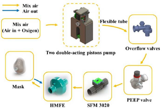
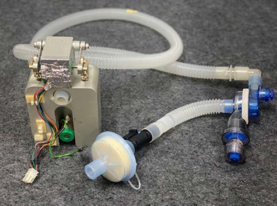
Figure 1 describes the operation process of DAPP system. In which, the DAPP is driven by a brushless direct current (BLDC) motor. The flexible tube that is responsible for air transmission between each part of the system is made of medical specialized silicon. The DAPP also uses two types of exhausting valves. The first type is the overflow valve. The overflow valve gives the ability for the DAPP system to exhaust the air when the pressure in the system increases above the limit pressure. This helps to protect the system from being damaged. The other exhausting valve is the positive end-expiratory pressure (PEEP) valve, which is used for maintaining the residual pressure existing in the patient’s lung at the end of the expiration phase. This PEEP valve plays an important role in assisting patient’s breath and avoiding collapsed lungs which has the possibility of augmenting the mortality rate of patients [20]-[23]. Besides these exhausting valves, a mass flow sensor SFM 3020 manufactured by SENSIRON is included in the system with the purpose of retrieving airflow data on the outlet. The pumped mixed air must be filtered by a heat moisture exchanger filter (HMEF) before entering patient’s respiratory system. The HMEF contributes to humidification, warming-inspired air. It also helps to capture airborne particles and prevent bacteria or viruses from flowing into the patient. Additionally, the usage of the HMEF can help to isolate the contaminated airflow from the patient to the DAPP system during the exhalation.
3. Model identification
Upon present literature in the model identification and control field, the FOPDT model still receives considerable attraction due to its simplicity and well performance in fitting many industrial processes. A FOPDT model can be written as follow:
| (1) |
where τp is the time constant; y(t) is the response signal of the system; Kp is the process gain or the steady state gain; u(t) is the input signal of the system and θp is the dead time. By calculating three parameters τp, Kp, θp based on the sample data, the DAPP system can be identified in form of an estimated FOPDT model. Numerous methods were studied and applied in determining or approximating these parameters [24]-[27]. Among them, there is a class of methods that use the step response of the system to estimate the FOPDT model. Typically, the graphical method and area method was introduced by document [28] to estimate FOPDT model based on the step response. The two-points method [29] is also a simple one for this application. However, all three mentioned methods were sensitive with noise, and a novel method was proposed in the document [30] in which the least-squares method was applied to calculate the parameters of the FOPDT model.
In this paper, the graphical method is adopted for model identification of the DAPP system because of the simplicity of the method and the low-noise characteristic of the DAPP. According to this method, the parameters τp, Kp, θp are identified based on the step response of the DAPP system. Let’s define uss, yss respectively as the steady state input and the output signal of the system. Assume that two separated steady-state output signals yss1,yss2 with respect to two steady-state signals uss1, uss2 are recorded through experimental tests. The process gain Kp can be determined as the following equation.
| (2) |
From the step response graph, the process dead time θp is defined as the time period between the beginning when the system is excited by a step input and the time when the state transition of the system is initialized. With this definition, the dead time can be estimated visually by one when conducting the experimental tests or calculated by using the intercept of the tangent line with the horizontal axis.
After determining parameters Kp and θp, Equation (1) can be rewritten in form of:
| (3) |
By shifting the time origin of the step response to an amount that equals the dead time, the dead time θp , which is the alternative time origin, can be neglected in Equation (1) (θp = 0 ). Hence, at the time t = τp, the airflow output of the DAPP system is calculated as
| (4) |
According to Equation (4), by identifying the time t0.632 when the airflow output reaches 63.2% of the steady state output value yss, the time constant is derived by the difference t0.632 − θp.
The whole identification process is summarized in form of a pseudo-code algorithm and shown in Table 1.
4. Experimental tests
The aim of this section is to provide experimental features of the tests which are conducted for collecting input-output data from the DAPP system. Furthermore, the model identification process of the DAPP system with the collected data is presented. And at the end of this section, the results and validation of the identified model are illustrated and discussed.
4.1 Experiment specifications
In order to produce calculation and model estimation of the DAPP system by the graphical method, the step response graph must be established. This can be accomplished by recording data of the step input signals and the airflow response signals. Exciting the DAPP system with different voltages input, the corresponding output data is recorded by the mass flow sensor mentioned in Section 2. The voltage excitation of the DAPP system is conducted 10 times with 10 distinct voltage values in form of pulse width modulation (PWM) pulses ranging from 10% to 55% duty cycle. The retrieved data is then divided into 2 groups; the first group of data is used for the purpose of model identification, and the other is served as validation data for the recently identified model. Moreover, to ensure the new steady state is achieved after the excitation, each scenario has a duration of 5 seconds and the sampling time is 10 milliseconds (ms).
4.2 Identification process
After the previous sub-section, groups of data are achieved and will be used for identifying the parameters of the FOPDT model in this subsection. The first parameter in the FOPDT equation that needs to be determined is the dead time θp. According to the graphical method, this parameter is defined as the intercept of the tangent to the step response that has the largest slope with respect to the horizontal axis. In order to accomplish that, the line equation of the tangent to the step response must be established as the highest priority. Then, by generating data from each scenario of input in the 1st group through that equation, the tangent with the largest slope is found and the corresponding dead time is determined. The process gain is calculated from the step response in each scenario according to Equation (2). Following the algorithm in Table 1, the time constant can also be estimated. Finally, a comparative evaluation of each parameter among scenarios in the 1st group is carried out and the FOPDT model of the pump system is fully identified.
4.3 Results and validation
The entire experimental tests and the calculated parameters in each scenario are also included in Table 2.
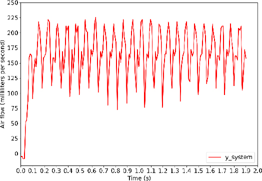
For a full explanation of the above table, a brief view of the step response graph is indeed needed. Figure 3 shows the output response curve and the corresponding step input which belong to the 1st test scenario. It can be seen from the figure that the system took a small period of time to start the state transition. This amount of time results from the inertia relying on the pump system itself which prevents the system from responding to the input voltage signal immediately. By this means, the dead time θp acts the same way as the delay time in Figure 3. As consequently, it can be estimated as 0.04 seconds.
After the derivation of the dead time, the time constant is computed by following the algorithm in Table 1. Hence, τ = t0.632 − θp ≈ 0.07 − 0.04 = 0.03 (s).
As can be seen from Table 2, the parameters τp among the scenarios oscillate around an equilibrium point (≈ 0.03 seconds) and the dead time θp remains constant as 0.04 seconds throughout every scenario. On the other hand, the process gain Kp tends to change its value in low levels of airflow (< 500 ml/s) due to the nonlinear characteristics of the DAPP at a low level of airflow. When the BLDC motor reaches the high level of duty cycle (> 20%), where the high level of airflow (> 500 ml/s) is generated by the DAPP. The gain Kpstarts to fluctuate between 511 and 549 with a mean value of about 533. This means that the DAPP system has linear characteristics in a high level of airflow. Therefore, the FOPDT model will be used for designing the controller of the DAPP system in high levels of airflow (> 500 ml/s). The final FOPDT model is derived as follows, after extracting the mean value from each parameter.
| (5) |
For the objectives of validation, the mean squared error (MSE) is used to evaluate the estimated model’s performance. The equation of MSE is defined as
| (6) |
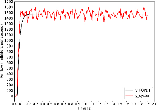
where is the steady state output airflow of the estimated FOPDT model in Equation (5); yss is the steady state output airflow of the DAPP system that is measured by the mass flow sensor, i denotes the number of samples in steady state in the rth scenario. The MSE score of the FOPDT model with the 2nd group of data is summarized in Table 3 below. Figure 4 below shows the comparative evaluation between the output airflow of the estimated FOPDT model and the airflow measured by the sensor in 10thscenario.
From Figure 4, one restriction of the FOPDT model could be pointed out, that is the estimated output values do not fit well with fluctuation in steady-state. This disadvantage could be troublesome when designing an airflow controller that requires high accuracy because some peak values might do harm to the system itself. Alternatively, using a model with higher order or applying another identification method is one of the solutions. However, with the objective of controlling the volume that is pumped into the patient’s lung, this estimated FOPDT model can be useful. In future work, research and studies on the volume controller based on this estimated FOPDT model will be conducted. Tuning the model parameter is also a branch to be concerned.
4. Conclusion
This paper presented an alternative method of system identification for medical ventilators. The FOPDT model was described and an algorithm was established to determine the parameters. The estimated model was then validated with the aspect of performance in the approximation system. Some restrictions of the model also are discussed. In future work, the volume parameters of the DAPP are going to be experimentally performed with the prosthetic lung and the change in output impedance (change in the internal resistance of the prosthetic lung). In addition, the intelligent controller is applied for DAPP to observe and update the coefficients to ensure in two situations: the volume is constant or the volume changes based on the impedance change of the prosthetic lung.
Acknowledgments
This paper is an expanded version of the proceeding paper entitled “Model identification of two double-acting pistons pump” presented at the ICACE 2022.
This research is funded by Vietnam National University Ho Chi Minh City (VNU-HCM) under grant number TX2023-20b-01.We acknowledge the support of time and facilities from National Key Laboratory of Digital Control and System Engineering (DCSELab), Ho Chi Minh City University of Technology (HCMUT), VNU-HCM for this study.
Author Contributions
Conceptualization, D. K. Nguyen and C. T. Truong; Methodology, D. K. Nguyen and C. T. Truong; Software, D. K. Nguyen; Validation, D. K. Nguyen and T. T. Nguyen; Formal Analysis, C. T. Truong; Investigation, T. T. Nguyen; Resources, C. T. Truong; Data Curation, D. K. Nguyen; Writing—Original Draft Prepara-tion, D. K. Nguyen and C. T. Truong; Writing—Review & Editing, V. T. Duong; Visualization, D. K. Nguyen and C. T. Truong; Supervision, V. T. Duong; Project Administration, H. H. Nguyen; Funding Acquisition, T. T. Nguyen.
References
-
H. Harapan et al., “Coronavirus disease 2019 (COVID-19): A literature review,” Journal of Infection and Public Health, vol. 13, no. 5, pp. 667-673, 2020.
[https://doi.org/10.1016/j.jiph.2020.03.019]

-
F. Jiang, L. Deng, L. Zhang, Y. Cai, C. W. Cheung, and Z. Xia, “Review of the clinical characteristics of coronavirus disease 2019 (COVID-19),” Journal of General Internal Medicine, vol. 35, no. 5, pp. 1545-1549, 2020.
[https://doi.org/10.1007/s11606-020-05762-w]

-
Yu Shi et al., “An overview of COVID-19,” Journal of Zhejiang University-SCIENCE B, vol. 21, no. 5, pp. 343-360, 2020.
[https://doi.org/10.1631/jzus.B2000083]

-
D. Kumar, R. Malviya, and P. K. Sharma, “Corona virus: a review of COVID-19,” Eurasian Journal of Medicine and Oncology, vol. 4, no. 1, pp. 8-25, 2020.
[https://doi.org/10.14744/ejmo.2020.51418]

-
N. Khan and M. Naushad, “Effects of Corona virus on the world community,” 2020.
[https://doi.org/10.2139/ssrn.3532001]

-
J. Hua and R. Shaw, “Corona virus (Covid-19) “Infodemic” and emerging issues through a data lens: The case of China,” International Journal of Environmental Research and Public Health, vol. 17, no. 7, 2020.
[https://doi.org/10.3390/ijerph17072309]

-
M. L. Ranney, V. Griffeth, and A. K. Jha, “Critical supply shortages — the need for ventilators and personal protective equipment during the Covid-19 pandemic,” The New England Journal of Medicine, vol. 382, no. 18, p. e41, 2020.
[https://doi.org/10.1056/NEJMp2006141]

-
S. Abrahamsson, F. Bertoni, A. Mol, and R. I. Martin, “Living with omega-3: New materialism and enduring concerns,” vol. 33, no. 1, pp. 4-19, 2015.
[https://doi.org/10.1068/d14086p]

-
M. Shahid, “Prototyping of artificial respiration machine using AMBU bag compression,” 2019 International Conference on Electronics, Information, and Communication (ICEIC), pp. 1-6, 2019.
[https://doi.org/10.23919/ELINFOCOM.2019.8706360]

-
D. S. Akerib et al., “A simple ventilator designed to be used in shortage crises: Construction and verification testing,” JMIR Biomedical Engineering, vol. 6, no. 3, p. e26047, 2021.
[https://doi.org/10.2196/26047]

-
C. T. Truong, K. H. Huynh, V. T. Duong, H. H. Nguyen, L. A. Pham, and T. T. Nguyen, “Linear regression model and least square method for experimental identification of AMBU bag in simple ventilator,” International Journal of Intelligent Unmanned Systems, 2022.
[https://doi.org/10.1108/IJIUS-07-2021-0072]

-
E. Castro-Camus et al., “Simple ventilators for emergency use based on bag-valve pressing systems: Lessons learned and future steps,” Applied Sciences, vol. 10, no. 20, pp. 1-15, 2020.
[https://doi.org/10.3390/app10207229]

-
J. Warren, R. E. Fromm, R. A. Orr, L. C. Rotello, and H. Mathilda Horst, “Guidelines for the inter- and intrahospital transport of critically ill patients,” Critical Care Medicine, vol. 32, no. 1, Critical Care Medicine, vol. 32, no. 1, pp. 256-262, 2004.
[https://doi.org/10.1097/01.CCM.0000104917.39204.0A]

-
B. Blackwood, J. Wilson-Barnett, C. C. Patterson, T. J. Trinder, and G. G. Lavery, “An evaluation of protocolised weaning on the duration of mechanical ventilation,” Anaesthesia, vol. 61, no. 11, pp. 1079-1086, 2006.
[https://doi.org/10.1111/j.1365-2044.2006.04830.x]

-
R. Robert, P. Micheau, S. Cyr, O. Lesur, J. -P. Praud, and H. Walti, “A prototype of volume-controlled tidal liquid ventilator using independent piston pumps,” ASAIO Journal, vol. 52, no. 6, pp. 638-645, 2006.
[https://doi.org/10.1097/01.mat.0000249016.31910.11]

-
J. Živčák et al., “An adaptive neuro-fuzzy control of pneumatic mechanical ventilator,” Actuators, vol. 10, no. 3, p. 51, 2021.
[https://doi.org/10.3390/act10030051]

-
C. T. Truong, K. H. Huynh, V. T. Duong, H. H. Nguyen, L. A. Pham, and T. T. Nguyen, “Model-free volume and pressure cycled control of automatic bag valve mask ventilator,” AIMS Bioengineering, vol. 8, no. 3, pp. 192-207, 2021.
[https://doi.org/10.3934/bioeng.2021017]

- R. W. Crawford, C. R. Platt, F. Zheng, and C. Beuchat, Pump piston assembly with acoustic dampening device, United States, US 2013/0081536A1, April 4, 2013.
- C. Adahan, Reciprocating machine, United States, US5762480A, June 9, 1998.
-
J. G. Muscedere, J. B. M. Mullen, K. Gan, and A. S. Slutsky, “Tidal ventilation at low airway pressures can augment lung injury,” American Journal of Respiratory Critical Care Medicine, vol. 149, no. 5, pp. 1327-1334, 1994.
[https://doi.org/10.1164/ajrccm.149.5.8173774]

- H. H. Webb and D. F. Tierney, “Experimental pulmonary edema due to intermittent positive pressure ventilation with high inflation pressures. Protection by positive end-expiratory pressure,” American Review of Respiratory Disease, vol. 110, no. 5, 1974.
-
L. Tremblay, F. Valenza, S. P. Ribeiro, J. Li, and A. S. Slutsky, “Injurious ventilatory strategies increase cytokines and c-fos m-RNA expression in an isolated rat lung model,” vol. 99, no. 5, pp. 944-952, 1997.
[https://doi.org/10.1172/JCI119259]

-
D. J. Tschumperlin, J. Oswari, and S. S. Margulies, “Deformation-induced injury of alveolar epithelial cells effect of frequency, duration, and amplitude,” vol. 162, no. 2, 1998.
[https://doi.org/10.1164/ajrccm.162.2.9807003]

-
F. S. Coelho and P. R. Barros, “Continuous-time identification of first-order plus dead-time models from step response in closed loop,” IFAC Proceedings Volumes, vol. 36, no. 16, pp. 393-398, 2003.
[https://doi.org/10.1016/S1474-6670(17)34793-6]

-
P. Bagheri and A. K. Sedigh, “Analytical approach to tuning of model predictive control for first-order plus dead time models,” IET Control Theory & Applications, vol. 7, no. 14, pp. 1806-1817, 2013.
[https://doi.org/10.1049/iet-cta.2012.0934]

-
A. Roy and K. Iqbal, “PID controller tuning for the first-order-plus-dead-time process model via Hermite-Biehler theorem,” ISA Transactions, vol. 44, no. 3, pp. 363-378, 2005.
[https://doi.org/10.1016/S0019-0578(07)60210-9]

-
Q. Bi, W. -J. Cai, E. -L. Lee, Q. -G. Wang, C. -C. Hang, and Y. Zhang, “Robust identification of first-order plus dead-time model from step response,” vol. 7, no. 1, pp. 71-77, 1999.
[https://doi.org/10.1016/S0967-0661(98)00166-X]

-
C. C. Hang and D. Chin, “Reduced order process modelling in self-tuning control,” Automatica, vol. 27, no. 3, pp. 529-534, 1991.
[https://doi.org/10.1016/0005-1098(91)90110-N]

- T. Marlin, Process Control: Designing Processes and Control Systems for Dynamic Performance. McGraw-Hill Education, 1995.
-
Q. -G. Wang, C. -C. Hang, and B. Zou, “Low-order model-ing from relay feedback,” Industrial & Engineering Chem-istry Research, vol. 36, no. 2, 1997.
[https://doi.org/10.1021/ie960412+]


