Thermal performances of protrusion-pyramid arrays in a parallel flow
Copyright ⓒ The Korean Society of Marine Engineering
This is an Open Access article distributed under the terms of the Creative Commons Attribution Non-Commercial License (http://creativecommons.org/licenses/by-nc/3.0), which permits unrestricted non-commercial use, distribution, and reproduction in any medium, provided the original work is properly cited.
Abstract
This study discusses thermal performances of the Protrusion-Pyramid Array (PPA) in a parallel flow. The PPA consists of the protrusions and the inverted pyramids in an inline array. The 3D CFD thermal-fluid model of the PPA is generated, verified by the measurement, and utilized to explore parametric influences on the PPA. It is found that the PPA enhances nearly 1.8 times of heat transfer, comparing with a smooth surface, with the PP diameter of 2.5mm at Re of 1200. The study also finds that the net PPA performance, considering both heat transfer enhancement and pressure loss, is approximately 1.2 times superior to the smooth surface associated with the PP heights of 2 and 2.5mm and the PP diameters of 3.5 and 4mm at Re ranging from 800 to 1600.
Keywords:
PPA, Parallel flow, Heat transfer enhancement, Performance factor1. Introduction
Heat densities of electronic systems have been increasing due to the strong demands of the miniaturization and high performance. The increase of heat density induces the lifetime reduction as well as the performance degradation of the electronic system [1]. Classical finned heat sinks may not be appropriate to manage waste heat and temperature of electronic systems of high-end electric ships and naval vessels requiring forced convection cooling in limited spaces. Hence, the novel design of the low profile extended surface is necessary.
Dimples and protrusions of low profile surfaces may enhance heat transfer by creating secondary flows with moderate pressure drops. Ligrani et al. [2]-[4] found the deeper the dimple, the better the heat transfer enhancement. However, the greater pressure drop was also observed with the increase of the dimple depth. Ha et al. [5][6] found the friction factor was considerably dependent on the ratio of the protrusion height to the channel height, and they demonstrated the vortex generator behind the dimples enhanced heat transfer rates. Cho et al. [7][8] found that heat transfer was enhanced by 2.2 times for dimple surfaces, by 2.7 times for protrusion surfaces, and by 2.5 times for dimple-protrusion surfaces compared with smooth surfaces.
In this paper, a novel low profile extended surface is introduced.
It is referred to as a Protrusion-Pyramid Array (PPA). Methodology of the 3-D CFD thermal-fluid analysis and experimental verification are discussed. Then, the paper discusses analysis results for parametric influences, including the diameter, the height, the depth of the dimple and the pyramid, on heat transfers and performance factors of the PPA.
2. Protrusion-Pyramid Arrays
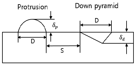
The PPA was proposed to maintain the heat transfer enhancement of the protrusions and the alleviation of the pressure loss through the inverted pyramids. The inverted pyramid is axially symmetric for the flow direction. The declination angle of the front part of the inverted pyramid was proposed to be moderate to mitigate the press loss. Figure 1 illustrates the structure and the physical parameters of the one line of the PPA. In Figure 1, D denotes either a protrusion diameter or a pyramid length, δp denotes the height of the protrusion, and δd denotes the depth of the inverted pyramid.
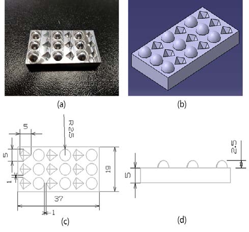
Consequently, the PPA is an inline array of protrusions and inverted pyramids as shown in Figure 2. The baseline PPA is also shown Figure 2. The protrusion diameter is 5 mm, both the width and the length of the pyramid are 5 mm, the height and the depth for the protrusion and the pyramid are 2.5 mm, the base area is 19 mm x 37 mm, the base thickness is 5 mm for the baseline PPA. The base material for the PPA is Al6061.
3. CFD Thermal-Fluid Model
3.1 Model Methodology
In this study, the 3-D CFD thermal-fluid model was generated. ANSYS ICEM CFD and FLUENT were used for the computational grid generation and calculation. In this analysis, a steady, incompressible, and laminar flow was assumed. Governing equations for modelling are shown as follows. Equation (1) is continuity equation, Equations (2) to (4) are momentum equations, Equation (5) is energy equation [9][10].
| (1) |
| (2) |
| (3) |
| (4) |
| (5) |
where u, v, w are air velocities in x, y, z directions, P is pressure, ρ is density, ν is kinematic viscosity, α is thermal diffusivity.
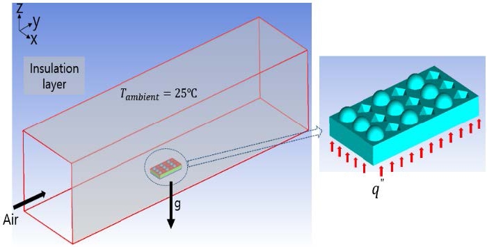
Figure 3 shows the thermal-fluid model and boundary conditions of a PPA. The air flow is a parallel flow in the axial direction, and the PPA base is uniformly heated in the model. The details regarding physical and numerical conditions are summarized in Table 1.
The physical and numerical conditions, especially the heat flux value and laminar flow assumption, were selected since the study result could be utilized to design a thermal management solution for amplifier chips in the condition of a moderate air flow velocity.
3.2 Performance factor
Equations (6) to (9) show defined convection heat transfer coefficient, h, Nusselt number, Nu, friction coefficient, f, and performance factor, PF. PF is defined as the ratio of heat transfer to the pressure loss, and it is used to evaluate a figure of merit of the PPA. In Equation (9), the exponent of 1/3 in the denominator is explained by the relationship between friction and Reynolds number: Res/Re = (f/fs)1/3.
| (6) |
| (7) |
| (8) |
| (9) |
where q" is heat flux at the PPA base, Tb is the base temperature of the PPA, T∞ is ambient temperature, Dh is a hydraulic diameter of the channel, kf is fluid thermal conductivity, ΔP is pressure loss per unit length, U is flow velocity, Nus and fs are Nusselt number and friction coefficient for a smooth surface.
4. Experimental Validation
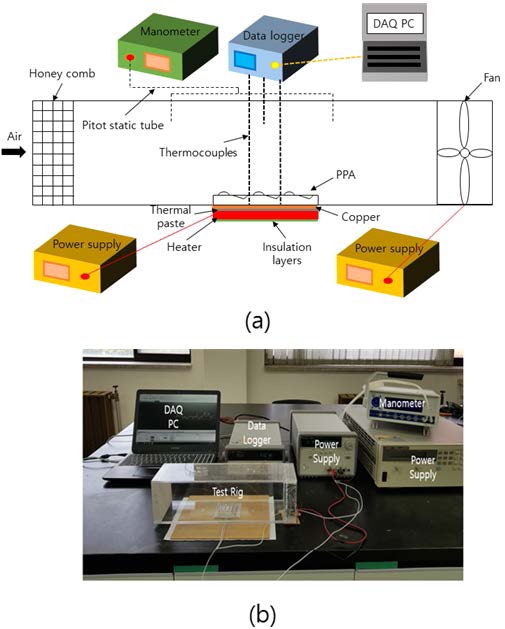
In order to verify the CFD thermal-fluid model, the test rig was implemented as shown in Figure 4. The heating part consists of a film heater (MRHSK-50-50-V100-W20), a thermal paste (AREMCO 639), 5mm thick Copper heat spreader, and insulation layers (Aerogel). The film heater provides the PPA base of uniform heat flux, and insulation layers minimize the unavoidable heat loss.
A 100 mm wide, 100mm high, and 400 mm long rectangular channel to provide parallel flows to the PPA was fabricated by 5 mm thick PMMA plates. A DC fan (SUNON GE92252B1) in the outlet and a honeycomb in the inlet were placed to provide fully developed air flows through the PPA. Incoming air velocity to the channel was monitored by a high precision digital manometer (FCO560) with a pitot static tube (FCO65-F225). Equipment and components composing the test rig is well summarized in Table 2.
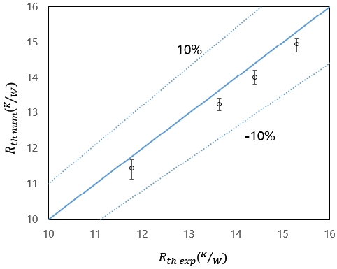
To validate the CFD thermal-fluid model, calculated thermal resistances of the PPA were compared with measured values. Thermal resistance, Rth, of the PPA is simply defined as (Tb−T∞)/q where Tb is the PPA base temperature, T∞is the ambient temperature, and q is the heat dissipation of the PPA. The validation results are shown in Figure 5. It is seen that the average discrepancy between the calculation and the measurement is within 3%. This small discrepancy result assures the robustness of the CFD thermal–fluid model utilized for the further analysis.
5. Parametric Influences
This section discusses the influences of the height and diameter of the Protrusion-Pyramid (PP) on Nusselt numbers, Nu, normalized Nusselt numbers, Nu/Nus, and performance factors, PF, of the PPA associated with various Reynolds numbers, Re. Figures 6 to 8 show those parametric influences.
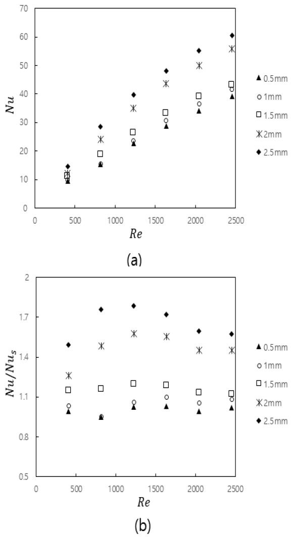
(a) Nusselt numbers and (b) normalized Nusselt num-bers of the PPA as a function of Reynolds number with various heights of the PP
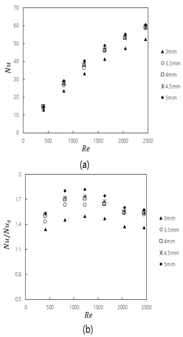
(a) Nusselt numbers and (b) normalized Nusselt numbers of the PPA as a function of Reynolds number with various diameters of the PP
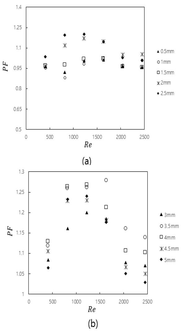
Performance factors of the PPA as a function of Reynolds number with (a) various heights and (b) diameters of the PP
It should be noted that the protrusion height is equal to the inverted pyramid depth, and the protrusion diameter is equal to both width and length of the inverted pyramid for all the calculated results.
In Figures 6 (a) and (b), the diameter of the PP is 5mm. Figure 6 (a) shows Nu values increase with the increase of Re despite the variance of the PP height. It also shows that Nu values increase with the increase of the PP height at a consistent PP diameter, and it is mainly due to the surface area enhancement with the increase of height. Figure 6 (b) shows the optimum Nu/Nus value is 1.8 at Re of 1200. This result implies that 1.8 times heat transfer enhancement by the PPA, comparing with a smooth surface without any PPs, occurs at Re of 1200.
In Figures 7 (a) and (b), the height of the PP is 2.5 mm. Figure 7 (a) shows Nu values increase with the increase of Re despite the variance of the PP diameter. It also shows that Nu values increase with the increase of the PP diameter at a consistent PP height, and the surface area enhancement may explain this result. Figure 7 (b) shows Nu/Nus values are greater than 1.4 from Re of 500 to 1500; it denotes 1.4 times heat transfer enhancement by the PPA compared with a smooth surface. Figure 8 (a) shows the optimum PF value is 1.2 with the PP height of 2.5 mm at Re of 1200. Figure 8 (b) shows the optimum PF value is 1.28 with the PP diameter of 3.5mm at Re of 1600. The results suggest that the performance of the PPA would be considerably better with the PP heights of 2 and 2.5mm and the PP diameters of 3.5 and 4mm at Re ranging from 800 to 1600.
Considering the baseline geometry, the Nu and friction factor values of the PPA would be smaller than the dimple-protrusion surface. The diameter, height, depth, and spacing might be crucial parameters for the performance of the PPA. Hence, the sophisticated optimization of the PPA structure should be needed in order to compare with other low profile extended surfaces including the dimple-protrusion surface.
6. Conclusion
In this study, the PPA was proposed as a novel low profile extended surface. The PPA is an inline array of protrusions and inverted pyramids. The 3-D CFD thermal-fluid model was generated, experimentally validated, comprehensively used to investigate parametric influences on the heat transfer and performance factor of the PPA with a parallel flow. The primary results are shown as follows: The result shows that 1.8 times heat transfer enhancement by the PPA, comparing with a smooth surface, occurs with the PP diameter of 2.5 mm at Re of 1200. The result shows that the net performance of the PPA would be about 1.2 times better than the smooth surface associated with the PP heights of 2 and 2.5 mm and the PP diameters of 3.5 and 4 mm at Re ranging from 800 to 1600.
Acknowledgments
This research was supported by Pukyong National University Development Project Research Fund, 2019.
Author Contributions
Conceptualization, B. G. Kim; methodology, B. G. Kim; Software, D. I. Yu; Formal Analysis, B.G. Kim; Investigation, B. G. Kim ; Resources, J. H. Lee; Data curation B. G. Kim; Writing-Original Draft Preparation, K. J. Kim and B. G. Kim; Writing-Review & Editing, K. J. Kim; Visualization, Y. W. Lee; Supervision, K. J. Kim; Project Administration, K. J. Kim; Funding Acquisition, K. J. Kim.
References
-
N. S. Effendi and K. J. Kim, “Computational study of orientation effects on thermal performance of natural convection cooled lightweight high performance hollow hybrid fin heat sinks,” Journal of the Korean Society of Marine Engineering, vol. 40, no. 9, pp. 786-790, 2016 (in Korean).
[https://doi.org/10.5916/jkosme.2016.40.9.786]

-
P. M. Ligrani, G. I. Mahmood, J. L. Harrison, C. M. Clayton, and D. L. Nelson, “Flow structure and local Nusselt number variations in a channel with dimples and protrusions on opposite walls,” International Journal of Heat and Mass Transfer, vol. 44, no. 23, pp. 4413-4425, 2001.
[https://doi.org/10.1016/S0017-9310(01)00101-6]

-
G. I. Mahmood, P. M. Ligrani, "Heat transfer in a dimpled channel: combined influences of aspect ratio, temperature ratio, Reynolds number, and flow structure,” International Journal of Heat and Mass Transfer, vol. 45, no. 10, pp. 2011-2020, 2002.
[https://doi.org/10.1016/S0017-9310(01)00314-3]

-
N. K. Burgess, P. M. Ligrani, "Effects of dimple depth on channel Nusselt numbers and friction factors,” Journal of Heat Transfer, vol. 127, no. 8, pp. 839-847, 2005.
[https://doi.org/10.1115/1.1994880]

-
J. H. Doo, H. S. Yoon, and M. Y. Ha, “Study on improvement of compactness of a plate heat exchanger using a newly designed primary surface,” International Journal of Heat and Mass Transfer, vol. 53, no. 25-26, pp. 5733-5746, 2010.
[https://doi.org/10.1016/j.ijheatmasstransfer.2010.07.066]

-
J. E. Kim, J. H. Doo, M. Y. Ha, H. S. Yoon, and C. Son, “Numerical study on characteristics of flow and heat transfer in a cooling passage with protrusion-in-dimple surface,” International Journal of Heat and Mass Transfer, vol. 55, no.23-24, pp. 7257-7267, 2012.
[https://doi.org/10.1016/j.ijheatmasstransfer.2012.07.052]

-
S. D. Hwang, H. G. Kwon, and H. H. Cho, “Heat transfer with dimple/protrusion arrays in a rectangular duct with a low Reynolds number range,” International Journal of Heat and Fluid Flow, vol. 29, no. 4, pp. 916-926, 2008.
[https://doi.org/10.1016/j.ijheatfluidflow.2008.01.004]

-
S. D. Hwang, H. G. Kwon, and H. H. Cho, “Local heat transfer and thermal performance on periodically dimple-protrusion patterned walls for compact heat exchangers,” Energy, vol. 35, no. 12, pp. 5357-5364, 2010.
[https://doi.org/10.1016/j.energy.2010.07.022]

- K. A Hoffmann and S. T. Chiang, Computational Fluid Dynamics: I, 3rd Ed., Wichita, KS, USA, Engineering Education System, 1998.
- ANSYS Inc., ANSYS Fluent User’s Guide (2018). Available: https://www.afs.enea.it/project/neptunius/docs/fluent/html/ug/main_pre.htm, .

