Kinematic manipulation of a large object using a leader–assistant mobile robot system
Copyright © The Korean Society of Marine Engineering
This is an Open Access article distributed under the terms of the Creative Commons Attribution Non-Commercial License (http://creativecommons.org/licenses/by-nc/3.0), which permits unrestricted non-commercial use, distribution, and reproduction in any medium, provided the original work is properly cited.
Abstract
This study investigated the transportation of large objects using multiple mobile robots. The transport strategy entails three phases: first, the robots couple with the object; second, they move to the goal position; and finally, the robots decouple from the object. In a previous study, we investigated the coupling and decoupling configurations of the first and third phases. This study examined a kinematic control method for the second phase. We developed a leader–assistant system, where the leader guides the object to track a given path and the assistants are the remaining robots providing supporting forces to move the object. We first formulated a kinematic model based on the velocity constraints at the coupling points of the robots and objects for motion manipulation, and then presented a path-tracking control method. The control method comprises two parts: controlling the heading angle of the leader for tracking a given path and controlling the object’s position. The motions of the assistants are automatically determined using kinematic relationships. Simulation results revealed that the leader–assistant system scheme can successfully move an object along a planned path.
Keywords:
Object transportation, Multiple robots, Leader–assistant system, Kinematic model, Kinematic control1. Introduction
The rapid development of the freight logistics industry has highlighted the growing challenge of efficiently moving cargo in environments such as ports, logistics centers, and warehouses. As the demand for reliable and user-friendly mechanical solutions increases, the need to reduce the dependence on manual labor has become more pressing, necessitating automated transport systems.
Numerous studies have reported that object transportation using a robotic system is feasible and efficient [1]-[10]. The related studies can be classified into three categories. First, the mobile robot(s) are connected to an object through additional actuators for transporting the object. Inglett and Rodríguez-Seda [1] and Morishita et al. [2] proposed a method for clamping an object using a pair of differential-wheeled mobile robots for cooperative transportation. Wada et al. [3][4] proposed an omnidirectional transport system using differential-wheeled mobile robots equipped with passive casters and actuators coupled to an object. Korayem and Dehkordi [5] proposed multiple mobile robots equipped with robotic arms for gripping objects. The robots in this category can firmly couple with the object using additional actuators; however, the control method becomes more complicated, significantly increasing the manufacturing cost and overall weight.
The second category relies on a storage structure without actuators, which establishes a physical connection with mobile robots and places the object in the designed structure for transport. Hunte and Yi [6] employed three mobile robots to transport objects placed on a deformable sheet collaboratively. Huang and Zhang [7] proposed a system wherein two robots were connected by a ball-string-ball structure to transport objects. This method is suitable for objects with different shapes and can simultaneously transport several objects. However, the handling structure may disintegrate when robots carry heavy loads, reducing the system’s efficiency. This method cannot achieve precise control of the position and orientation of an object.
The final category uses highly scalable swarms of robots with a caging strategy. Rangsichamras et al. [8] and Yamamoto et al. [9] divided robots into leaders and followers. The entire system would be controlled by the leader to fulfill the transport tasks.
Thus, various strategies have been proposed for transporting an object with mobile robots. However, recent studies significantly rely on additional actuators and are not effectively scalable. Therefore, several challenges remain in this field [10].
This study investigated object transportation using multiple mobile robots. The transport strategy is divided into three phases: first, the robots couple with the object, and subsequently, move to a goal position by tracking a given path, and finally, decouple from the object, as shown in Figure 1. Previously [11], we investigated the coupling and decoupling configurations of an object and robots, in which the robots could couple/decouple with/from an object without any actuators. This paper presents a kinematic control method for the second phase, which transports the object along given paths.
First, a leader–assistant robot system is introduced. The leader is the robot guiding the object to track a given path, whereas the assistants are the remaining robots that provide the force to move the target object. A kinematic control method is proposed to track a given path through this leader–assistant robot system scheme. Therefore, a kinematic model is formulated based on the velocity constraints at the coupling points, and a straight-line path-tracking control method using the kinematic model is presented. The control method consists of two parts: one controls the leader’s heading angle to track the path, and the other controls the position of the object. The motions of the assistants were automatically determined based on kinematic relationships.
The remainder of this paper is organized as follows. Section 2 formulates the kinematic model of the leader–assistant system. Section 3 presents a kinematic control method for path tracking. Section 4 details the numerical simulations performed to verify the effectiveness of the kinematic control method and discusses the results. Section 5 summarizes the conclusions drawn.
2. Kinematic Model
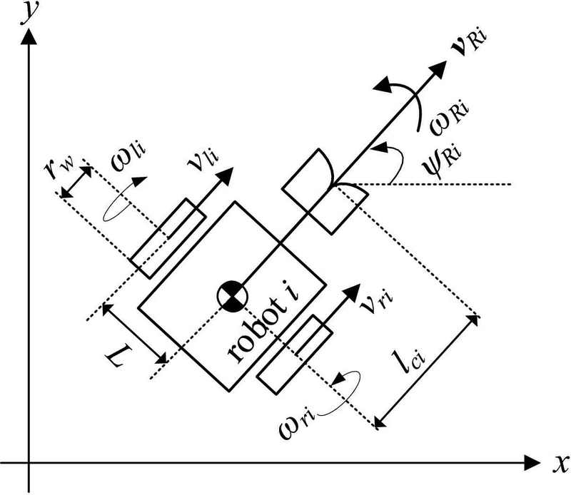
Figure 2 shows the model of a differential-wheeled robot with a coupling mechanism. Let rw be the radius of the wheel of the robot i (i = 1, ⋯, n), ωli and ωri be the angular velocities of the left wheel and right wheel, and L be the distance between the wheel and the center of the mass. The linear velocities of the left and right wheels, vli and vri, are given as
| (1) |
and the linear and angular velocities of the robot i, vRi∈𝕽2 and ωRi∈𝕽, can be obtained as
| (2) |
where ψRi is the heading angle of the robot i with respect to the x–y frame.
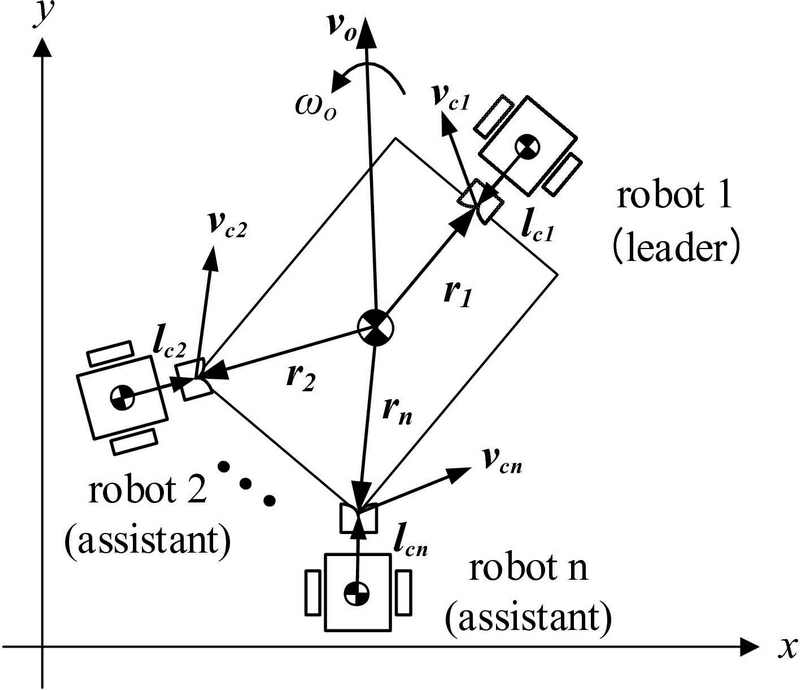
Multiple mobile robots that transport an object can be represented as shown in Figure 3. We consider n robots to formulate the generalized kinematic equations. The robot designated “leader” guides the object to follow a given path and the those designated “assistant” support the forces for moving the object.
Let vO∈𝕽2 and ωO∈𝕽 be the linear and angular velocities of the object, respectively. These can be manipulated by the linear and angular velocities of each robot, vRi and ωRi. We considered the velocity constraints at the coupling points to formulate the kinematic model of the leader–assistant system. Let vci∈𝕽2 be the velocity at the coupling point between the robot i and the object, ri∈𝕽2 be the position vector that points from the center of mass of the object to the coupling point with the robot i and lci∈𝕽2 be the position vector point from the center of the mass of the robot i to the coupling point; therefore,
| (3) |
| (4) |
where ri and lci are expressed with respect to the x–y frame, and E is the orthogonal rotation matrix rotating an arbitrary vector counterclockwise by 90o in a plane, and is given as
| (5) |
Considering the velocities at the coupling points of all the robots, we have
| (6) |
| (7) |
where , ,
, , and
.
Here, I2 is a 2×2 identity matrix, O2 is a 2×2 zero matrix, and 0 is a 2×1 zero vector.
From Equations (6) and (7), the following velocity constraints are obtained:
| (8) |
Thus, the forward and inverse kinematic models of the leader–assistant system can be obtained as follows:
| (9) |
| (10) |
where and are the pseudo-inverse of AO and AR, respectively.
3. Path Tracking Control
The control strategy is divided into two parts to enable the object to track the reference path:
- (i) control the position of the object; and
- (ii) control the heading angle of the leader to track a given path.
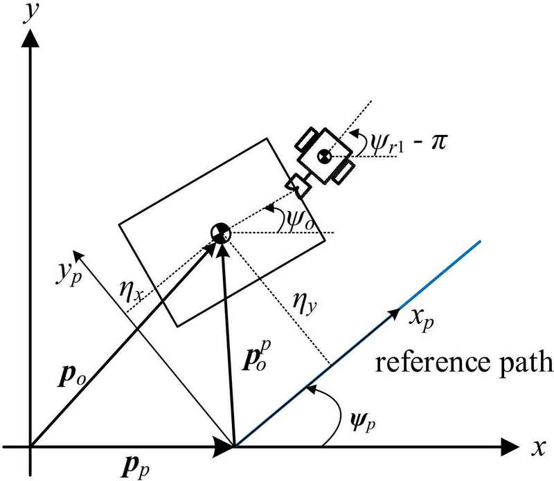
First, we consider controlling the position of the object. Figure 4 shows the notations used to track a straight path. Let pO and pp be the position vectors pointing to the object and the origin of the xp-yp frame (path frame), respectively, and = (ηx, ηy)T be the position vector of the object with respect to the path frame; therefore,
| (11) |
where ψp is the angle between the xp axis and the x axis, and R is the rotation matrix given by
| (12) |
If ηy approaches zero, the object can track a straight line (the xp-axis).
Next, the heading angle of the leader tracks the path if the error with the angle of the xp-axis approaches zero. The angular error ηψ between the heading angle of the leader (ψr1) and the angle of the xp-axis (ψp) can be obtained as
| (13) |
Consequently, the required linear velocities and heading rate of the leader to accomplish these two controls can be expressed as
| (14) |
where vrd is the desired moving speed, and k1 and k2 are the control gains. From Equation (9), the motion of the object caused by the motion of the leader can be calculated as
| (15) |
Here, and . Simultaneously, the motions of the assistant robots can be obtained using Equation (10) as follows:
| (16) |
where ,
, and
.
4. Simulation
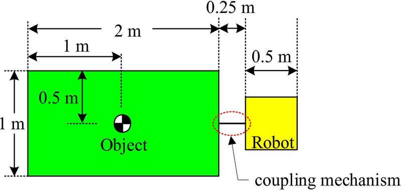
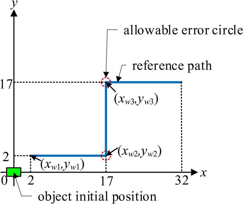
In this study, four cases were considered to verify the effectiveness of the kinematic control method of the leader–assistant system: the cases using one, two, three, and four robots. Figure 5 shows the sizes of the object and robot used in the simulation. The object is 2 m long and 1 m wide. The robot is 0.5 m in both length and width, while the coupling mechanism is 0.25 m long. Figure 6 shows the planned path consisting of three straight lines. The object is initially located at the origin of the x–y frame and is manipulated by the robots to track straight lines. At the second and third waypoints, (xw2, yw2) and (xw3, yw3), the path-tracking control is enabled if the object falls within the allowable error circle. The allowable error circle is given as
| (17) |
where po = (xo, yo)T is the object’s position, and re is the allowable error circle’s radius. For the simulations, the control gains were set to k1 = 1 and k2 = 1.9; the radius of the allowable error circle was re = 1.5 m, and the desired moving speed of the object was vrd = 0.5 m/s.
4.1 Using One Robot
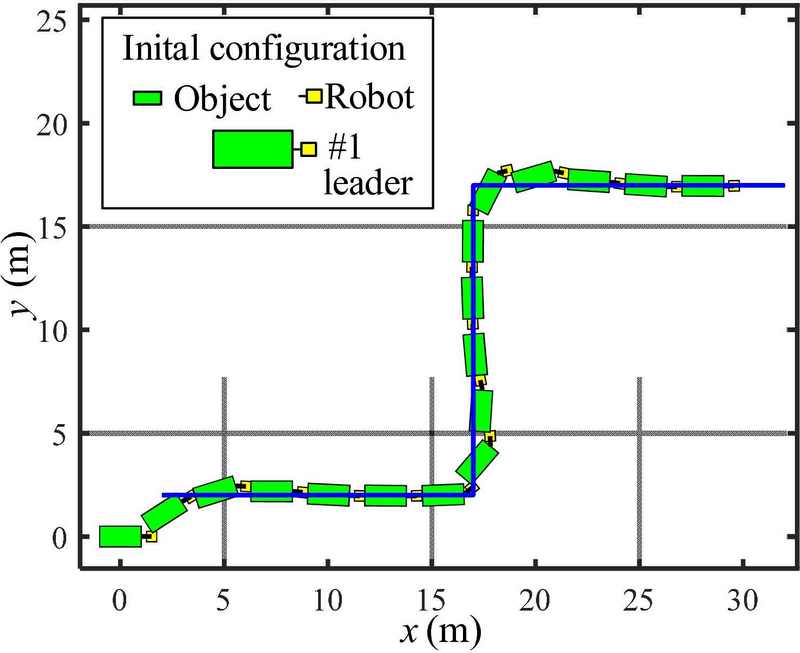
The leader is coupled to the object and pulls the object to track the given path. The initial position and heading of the object’s angle were (0, 0) m and ψo= 0o, and the initial position and leader’s heading angle were (1.5, 0) m and ψR1= 180o.
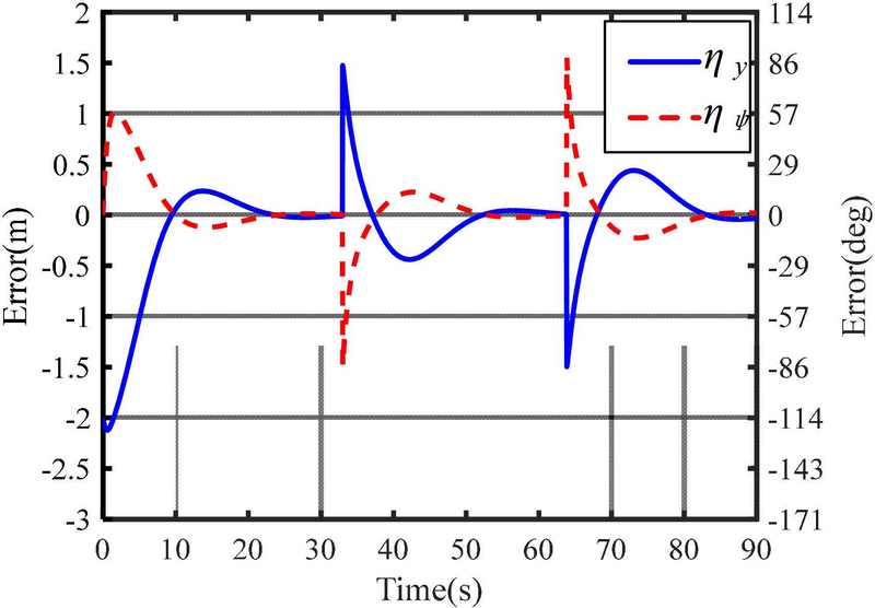
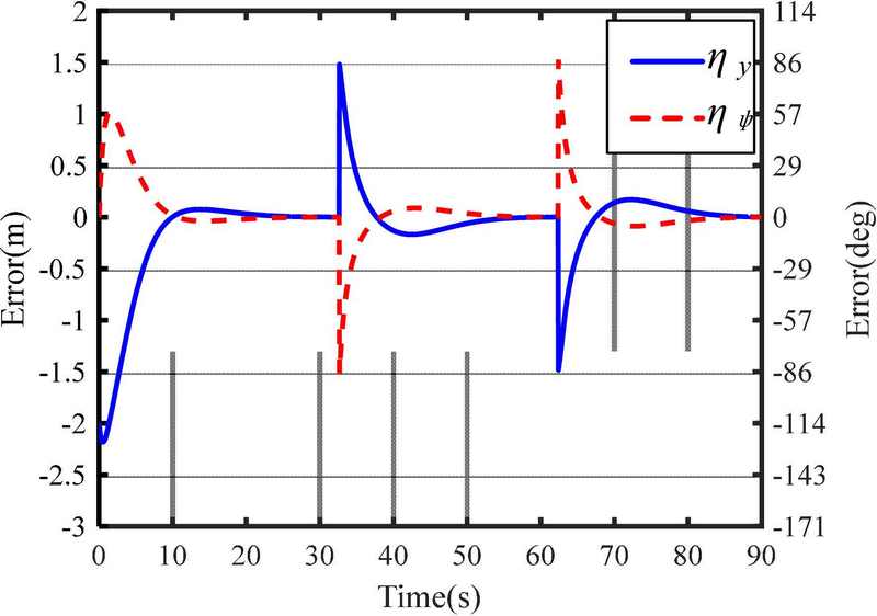
Figure 7 shows the simulation results for the path-tracking control. The leader could correctly guide the object to track the path. Figure 8 shows the position and heading errors, ηy and ηψ, respectively, expressed in Equations (11) and (13), during path tracking, whereby ηy and ηψ approaches zero. When turning at the second and third waypoints, the positional errors were approximately 1.5 m because the path-tracking control starts if the object’s position enters the allowance error circle with a radius of 1.5 m.
4.2 Using Two Robots
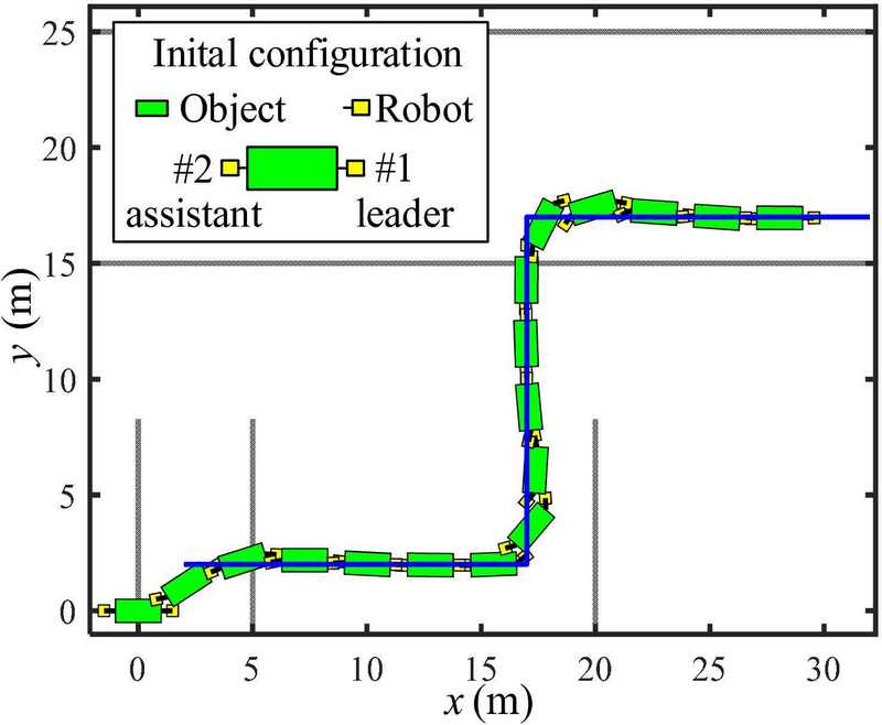
Figure 9 shows the case of using two robots—the leader and one assistant. The leader pulls and guides the object, and the assistant pushes it to support the force. The initial position and heading angle of the object are (0, 0) m and ψo= 0o. The initial positions and heading angles of the robots are given by (1.5, 0) m and ψR1= 180o for the leader; and (-1.5, 0) m and ψR2= 0o for the assistant. The object can effectively track the given straight-line paths. The position and heading errors became zero, as shown in Figure 10. This result is similar to that in Figure 8 because the initial positions and heading angles of the object and leader are similar to those in the scenario corresponding to Figure 7. Further, the control performances of the leaders are similar.
4.3 Using Three Robots
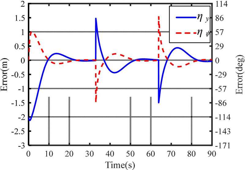
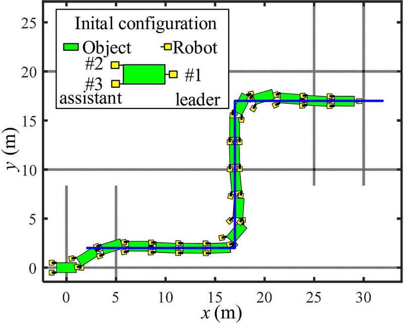
The simulations using three robots—a leader, and two assistants—were also conducted. The leader pulls the object, and the two assistants are pushed during transportation control. The initial position and heading angle of the object are (0, 0) m and ψo= 0o. The initial positions and heading angles of the robots are given by (1.5, 0) m and ψR1= 180o for the leader; (-1.5, 0.5) m and ψR2= 0o for Robot #2 in Figure 11; and (-1.5, -0.5) m and ψR3= 0o for Robot #3. The object was successfully transported along the path, as shown in Figures 11 and 12 .
4.4 Using Four Robots
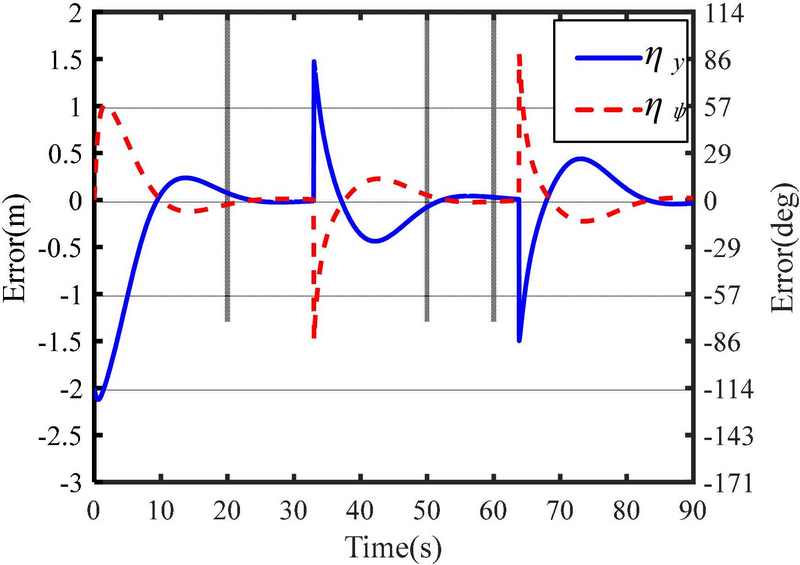
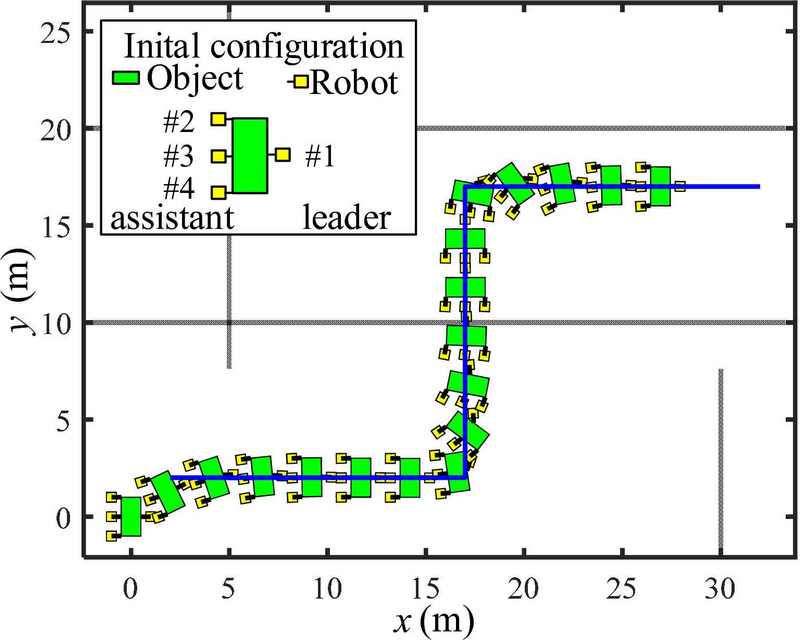
Figures 13 and 14 show the simulation results for the case of using four robots(i.e., a leader, and three assistants). The initial position and heading angle of the object are (0, 0) m and ψo= 90o. The initial positions and heading angles of the robots are given by (1, 0) m and ψR1= 180o for the leader; (-1, 1) m and ψR2= 0o for Robot #2; (-1, 0) m and ψR3= 0o for Robot #3; and (-1, -1) m and ψR4= 0o for Robot #4. The object was rotated by 90o at the initial position to couple with the three assistants. The results demonstrate that the proposed kinematic control method is effective for object transportation despite the number of robots. However, the errors in Figure 14 are smaller than those in Figures 8, 10, and 12 because the distance between the coupling point and the object’s center of mass is shorter than that of the others, and the response of the path-tracking control is faster.
5. Conclusion
In this study, we devised a leader–assistant robot scheme and a kinematic control method to enable an object track a planned path. The leader guides the tracking of the path, and the assistants support the force required to move an object. The results revealed that the proposed method is effective for multi-robot cooperative object transportation. In future research, we will focus on developing a dynamic control method for the leader–assistant system.
Author Contributions
Conceptualization, J. -K. Choi; Methodology, J. -K. Choi, H. Tian and H. -H. Kim; Software, H. Tian and J. -K. Choi; Formal Analysis, H. Tian, J. -K. Choi and H. -H. Kim; Investigation, H. Tian and J. -K. Choi; Resources, H. Tian and J. -K. Choi; Data Curation H. Tian and J. -K. Choi; Writing-Original Draft Preparation, H. Tian and J. -K. Choi; Writing-Review & Editing, J. -K. Choi, H. Tian and H. -H. Kim; Visualization, H. Tian and J. -K. Choi; Supervision, J. -K. Choi.
References
-
J. E. Inglett and E. J. Rodríguez-Seda, “Object transportation by cooperative robots,” Proceedings of IEEE Southeast Conference 2017, pp. 1-6, 2017.
[https://doi.org/10.1109/SECON.2017.7925348]

-
M. Morishita, S. Maeyama, Y. Nogami, and K. Watanabe, “Development of an omnidirectional cooperative transportation system using two mobile robots with two independently driven wheels,” Proceedings of IEEE International Conference on Systems, Man, and Cybernetics (SMC), pp. 1711-1715, 2018.
[https://doi.org/10.1109/SMC.2018.00296]

-
K. Miyashita and M. Wada, “An omnidirectional cooperative transportation of a large object by differential drive wheeled mobile robots with the active-caster control,” Proceedings of IEEE/SICE International Symposium on System Integration (SII), pp. 932-937, 2022.
[https://doi.org/10.1109/SII52469.2022.9708808]

-
Y. Arai and M. Wada, “Study on omnidirectional cooperative transport system using multiple dual-wheeled mobile robots with active-caster control,” Proceedings of IEEE/ASME International Conference on Advanced Intelligent Mechatronics (AIM), pp. 690-695, 2023.
[https://doi.org/10.1109/AIM46323.2023.10196226]

-
M. H. Korayem and S. F. Dehkordi, “Motion equations of cooperative multi flexible mobile manipulator via recursive Gibbs--Appell formulation,” Applied Mathematical Modelling, vol. 65, pp. 443-463, 2019.
[https://doi.org/10.1016/j.apm.2018.08.035]

-
K. Hunte and J. Yi, “Pose control of a spherical object held by deformable sheet with multiple robots,” IFAC-Papersonline, vol. 55, no. 37, pp. 414-419, 2022.
[https://doi.org/10.1016/j.ifacol.2022.11.218]

-
Y. Huang and S. Zhang, “Cooperative object transport by two robots connected with a ball-string-ball structure,” IEEE Robotics and Automation Letters, vol. 9, no. 5, pp. 4313-4320, 2024.
[https://doi.org/10.1109/LRA.2024.3379802]

-
P. Rangsichamras, N. Wittayaarereekul, S. Tantinarasak, I. Khuankrue and C. Janya-Anurak, “Cooperation of autonomous mobile robots with different maneuverability in transportation,” Proceedings of 62nd Annual Conference of the Society of Instrument and Control Engineers (SICE), pp. 187-192, 2023.
[https://doi.org/10.23919/SICE59929.2023.10354235]

-
Y. Yamamoto, Y. Hiyama, and A. Fujita, “Semi-autonomous reconfiguration of wheeled mobile robots in coordination,” Proceedings of IEEE International Conference on Robotics and Automation, pp. 3456-3461, 2004.
[https://doi.org/10.1109/ROBOT.2004.1308788]

-
X. An, C. Wu, Y. Lin, M. Lin, T. Yoshinaga, and Y. Ji, “Multi-robot systems and cooperative object transport: communications, platforms, and challenges,” IEEE Open Journal of the Computer Society, vol. 4, pp. 23-36, 2023.
[https://doi.org/10.1109/OJCS.2023.3238324]

-
J-K. Choi, H. Tian, and Y-S. Ha, “Object transportation using multiple mobile robots: coupling and decoupling configuration of an object and robots”, Journal of Advanced Marine Engineering and Technology, vol. 47, no. 6, pp. 360-366, 2023.
[https://doi.org/10.5916/jamet.2023.47.6.360]


