Validation and verification of simulation model for initial subcooled LPG filling into LFSS pipelines and fuel gas skid on LPG dual-fuel carrier
Copyright © The Korean Society of Marine Engineering
This is an Open Access article distributed under the terms of the Creative Commons Attribution Non-Commercial License (http://creativecommons.org/licenses/by-nc/3.0), which permits unrestricted non-commercial use, distribution, and reproduction in any medium, provided the original work is properly cited.
Abstract
At the initial start-up of low-flash point fuel gas supply system (LFSS), commissioning engineers place considerable emphasis on manually flowing liquefied petroleum gas (LPG) into the pipelines and fuel gas skid of the LFSS. For this purpose, they consider the vaporization of the LPG in relation to the pressure and temperature conditions within the LFSS. To alleviate the burden of manual operation for commissioning engineers and minimize system misoperation during the initial start-up, a stepped sequence for initially filling LPG into the pipelines and package was developed and simulated using Aspen HYSYS. This sequence entails confirming the system line-up, following a step-by-step procedure for LPG line pressurization and pump operation, and incorporating an alert system that detects any deviations from the preset values at each step. Each sequential step has an expected LPG condition, and guidelines with threshold values are displayed in both the simulation and monitoring systems of the vessel. All simulated data, parameters, and logic were validated and verified during the commissioning period of the gas trial on an LPG dual-fuel (DF) carrier. The simulated sequence, as well as the validation and verification during the gas trial, demonstrated that the initial LPG filling sequence can be a reliable tool for the commissioning of the LFSS. Further, the sequence will potentially reduce the risk of system misoperation by commissioning engineers and seafarers after the delivery of the ships.
Keywords:
Aspen HYSYS, Gas trial, Initial subcooled filling, Liquefied petroleum gas, Low-flash point fuel gas supply system, Simulation, Stepped sequence, Validation and verification1. Introduction
Since 2018, International Maritime Organization (IMO) has adopted an initial strategy on the reduction of green house gas emission from ships. Recently a “net-zero” carbon emission policy has been adopted, seeking to progressively achieve carbon zero by 2050. This strict emission control is accelerating the equipping of newly built ships with dual-fuel (DF) systems that can use fuels including liquefied natural gas (LNG) and liquefied petroleum gas (LPG) as the source of ship propulsion; these are much greener than conventional fossil fuels [1]. Previously, only LNG carriers were equipped with DF engines, and the LNG liquid gas in the cargo tank was utilized as the source of propulsion. However, with the advent of liquid gas injection (LGIP) engines, the use of cargo for propulsion has been extended to LPG carriers; LPG is now an additional fuel option that can be used in the two-stroke DF gas engine portfolio [2].
The LGIP engine requires the LPG liquid to be in a specific condition for combustion in gas mode with a pressure of 50 ± 2 bar and temperature of 35 ± 10 °C [3]. The LPG is supplied by the skid of a low-flash point fuel gas supply system (LFSS). To ensure the operability of the LGIP engine and guarantee the reliability of the LFSS, it is crucial to successfully commission the system during gas trials.
The adoption of LGIP engines and LFSS is fairly recent. Consequently, shipyard commissioning personnel may find it challenging to comprehend the properties of the LPG in an LFSS and appropriately handle the related system during commissioning.
The properties of LPG under various pressure and temperature conditions must be elucidated so as to mitigate the risk of significant pump or equipment failure due to phase changes caused by internal or external factors. Additionally, a limited number of commissioning engineers possess sufficient understanding of LPG properties and capability to suitably handle the LFSS. This presents a high risk of delays in ship delivery schedules, potentially leading to financial losses for shipbuilding companies.
Therefore, there is a growing need to develop a reliable tool that addresses the risks associated with manual operation during LFSS commissioning. This is particularly crucial when handling tasks such as introducing subcooled LPG into the pipelines and LFSS skid, venting LPG gas through the N2 separator, fully filling the system with LPG before starting the high-pressure (HP) pump, and supplying LPG into the LGIP engine.
In this study, a sequence of LPG filling was implemented in Aspen HYSYS and was further tested and validated via a gas trial with LPG DF carriers. The sequential steps begin with the checking of the pipelines and skid for LPG leaks after low-pressure (LP) pump commissioning. The sequence concludes with the filling of the N2 separator and skid with LPG under pressure from the LP pump. Each step of the sequence was thoroughly examined using Aspen HYSYS to prevent pump or equipment failure when the HP pump was started for supplying LPG to the LGIP engine. These sequential steps enhance the reliable and coherent commissioning of LFSS. Furthermore, its application can be extended to cases wherein the initial gas mode starts after a long-term stoppage onboard or after periodic docking events.
2. Simulation Model Description
2.1 LFSS Configuration
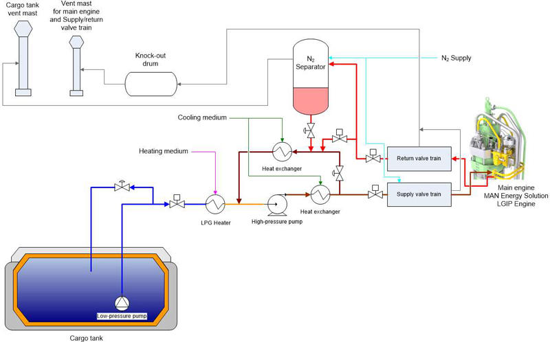
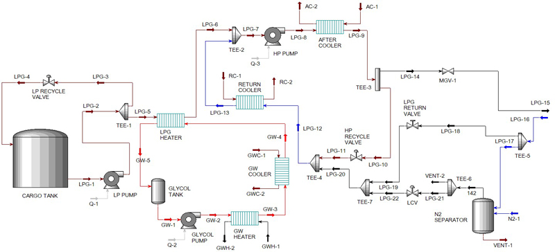
The typical configuration of an LFSS is depicted in Figure 1. The primary function of the LP pump is to deliver LPG to the HP pump. An LPG heater, facilitated by a glycol system, was employed to increase the temperature of the LPG. Two HP pumps were installed within the LFSS skid to boost the pressure of LPG and satisfy the requirements of the LGIP engine.
To ensure compliance with the desired temperature of LPG, the HP pump is equipped with an after-cooler that cools down its temperature to approximately 40 °C. The returned LPG passes through a return-LPG cooler and is fed into the inlet of the HP pump for recirculation.
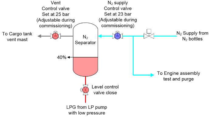
During system start-up and shutdown, the returned LPG flows into an N2 separator, where it is separated from the N2 used for pressure testing and purging in the fuel valve train (FVT). The N2 separator is equipped with a venting control valve that opens when the pressure exceeds the set pressure of 25 bar. The vented N2 is directed to the cargo tank vent mast. This study primarily focused on the commissioning phase, which includes step-by-step LPG leak testing of pipelines and skids under the pressure of the LP pump, as well as the phase prior to starting the HP pump. Each step was meticulously investigated using the Aspen HYSYS (version aspenONE V10), which was validated during the gas trial.
2.2 Dynamic Models of Main Equipment
The LP pump is a deep-well multistage centrifugal pump, and its dynamic characteristics are described by the pump curves and speed. LPG is considered incompressible, and the pump power is normally defined as follows:
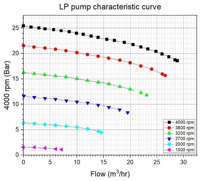
where Ps is the pump power, η is the pump efficiency, ρ is the fluid density, g is the gravitational constant, Q is the pump flow rate, and H is the pump head [4]. The pressure–flow relationship is determined by the curve corresponding to the pump speed. The pump curves used in this study are shown in Figure 2; these curves represent the boundaries of the LPG leakage test pressure. On the basis of the curves, the interrelationship between each pressure step for the LPG leak test can be understood, particularly in terms of the pump speed (RPM), flow rate, and pressure.
The HP pump is a side-channel pump, which is a small-volume vane pump with a low flow rate but high head. Most side-channel pumps can transport gas–liquid two-phase flows [5]. In the initial LPG filling sequence, the relevant step involving the HP pump is the skid-leak test at 21 bar; this step entails checking the tightness of the flanges at both the inlet and outlet connections of the HP pumps.
The fluid inside the tank is assumed to be in thermodynamic equilibrium. The summation of the heat flowing into the inner void space and the heat flowing out to the outer void spaces should be zero under a steady-state heat equilibrium. The following equation represents the heat equilibrium equation of the void space, ignoring the effect of radiation [6]:
where
where
2.3 Numerical Algorithm
Initially, a steady-state model is created in Aspen HYSYS to size equipment and perform energy and material balance calculations for the LFSS. Subsequently, this model is converted into a dynamic model by specifying the appropriate boundary and initial conditions. The implicit fixed-step-size Euler method is used to solve the ordinary differential equations. To balance accuracy and speed, the pressure–flow network was solved at every second and tenth time step. The Peng–Robinson equation of state was adopted to calculate the liquid–vapor equilibrium, with a time-step size of 0.5 s [7].
3. Experiment Description
3.1 Test Facility
The initial LPG filling process, which was numerically studied using Aspen HYSYS, was performed on the LFSS during a gas trial of the LPG DF carriers. After completing the LP pump commissioning, the process begins with step-by-step pressurization, including an LPG leak test and filling of the pipelines and skid equipment with LPG. The process concludes with the filling of LPG into the N2 separator. At the end of this initial LPG filling process, the system reaches a condition of 21 bar LPG pressure and 40% level in the N2 separator, with the pipelines and skid equipment fully filled with LPG. During the filling of LPG into the N2 separator, precise handling of the pressure settings for the venting and N2 supply pressure control valves is crucial. Any failure in this regard can introduce N2 into the LFSS, potentially leading to pressure hunting or even mechanical seal damage in extreme cases involving HP pumps. Details of the LFSS equipment used in the initial LPG filling process are summarized in Table 1.
3.2 Understanding of LPG Properties for LFSS
The operator of the LFSS must necessarily have a thorough understanding of the properties of LPG while the system is in operation. Essentially, the loaded LPG in the cargo tank is handled by the LP pump with -40 °C in the pipeline until the LPG reaches the glycol heater. Because the subcooled LPG temperature can be influenced by the ambient temperature, there is a risk of vaporization. This potential vaporization may have a negative effect on the pumps located within either the package or the pipeline, which are responsible for boosting the pressure on the skid.
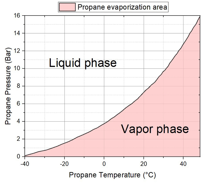
Figure 3 illustrates the relationship between the pressure and temperature of propane. The pressure–temperature diagram of LPG is an important thermodynamic characteristic of LPG storage, retrograde phenomena, vapor–liquid equilibrium, heating value, and boiling liquid–expanding vapor explosion phenomena. The curves of the pressure–temperature diagram differ depending on the composition of propane and butane in the LPG. Most commercial LPG are composed of 50%–90% propane and 10%–50% butane [8]. The composition of the LPG considered in Figure 3 is more than 90% propane, with a limited butane percentage.
The curve demonstrates that propane remains in liquid form in the areas above the curved line and vaporizes when the pressure and temperature conditions fall below the curve. However, during pauses in the LFSS operation while the LPG DF ship traverses tropical areas, the subcooled propane within the pipeline can readily vaporize under relatively low pressure. This phenomenon can lead to frequent trips when operating the LP pump after the pause and may have adverse effects on the skid.
To ensure safe operation and prevent failures related to propane vaporization characteristics, it is crucial for operators to possess a comprehensive understanding of this phenomenon.
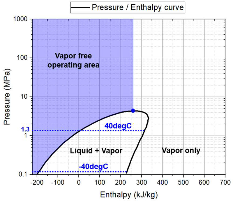
The Moliere chart can be utilized to determine the safe operation zone. Figure 4 illustrates the relationships among pressure, temperature, and enthalpy. The LFSS must be operated within the highlighted blue zone, as indicated, to avoid LPG vaporization and related pump mechanical seal damage.
3.3 LPG Leak Test
Upon successful completion of the LP pump commissioning, which ensures the full operation of the pump, the initial LPG filling sequence can commence with an LPG leak test. The LPG leak test consists of multiple carefully selected steps, which were determined through a thorough examination of the properties of LPG and using Aspen HYSYS simulation. The purpose of the LPG leak test in the initial LPG filling sequence is to prevent major leakages prior to system commissioning. This is crucial because LPG, when vaporized under ambient temperature and pressure, has a volume 250 times greater than that of the liquid form. As a result, LPG vapor at just 5% concentration in air creates approximately 5000 L of an inflammable and potentially explosive mixture, corresponding to approximately 6945 L of gas–air mixture under stoichiometric conditions [9]. Conducting a leak test helps ensure the integrity and safety of the system before it is commissioned and becomes operational.
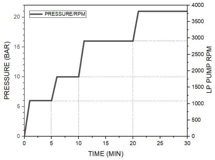
During each step of the leak test, the LPG pressure is incrementally increased to 6 bar, 10 bar, 16 bar, and finally 21 bar in Figure 5. The figure depicts the LPG leak test pressure steps, corresponding holding time, and LP pump RPM at each pressure level. The liquid characteristics of LPG suggests that vaporization does not occur when pressurizing the liquid propane beyond 16 bar under ambient temperatures exceeding 40 °C. Therefore, to ensure a vapor-free environment during filling and to effectively fill both pipelines and skid components with LPG, it is crucial for the initial filling sequence to include the complete venting of any existing LPG gas at this critical pressure point of 16 bar.
Essentially, the initial filling sequence includes a holding time for each pressure step. If any LPG leak is detected, the sequence must be immediately stopped and restarted. The first step of the LPG leak test began at 6 bar, and the corresponding pump speed at this pressure is approximately 1000 RPM.
During the sequence, a pop-up window is supposed to be displayed whenever the designed holding time for each pressure range is exceeded, which asks a permission to proceed to the next pressure range. The next pressure step is at 10 bar with 1800 RPM. The holding time setting is the same as that for pressure 6 bar and if there is no leak found, the pressure can be increased to 16 bar.
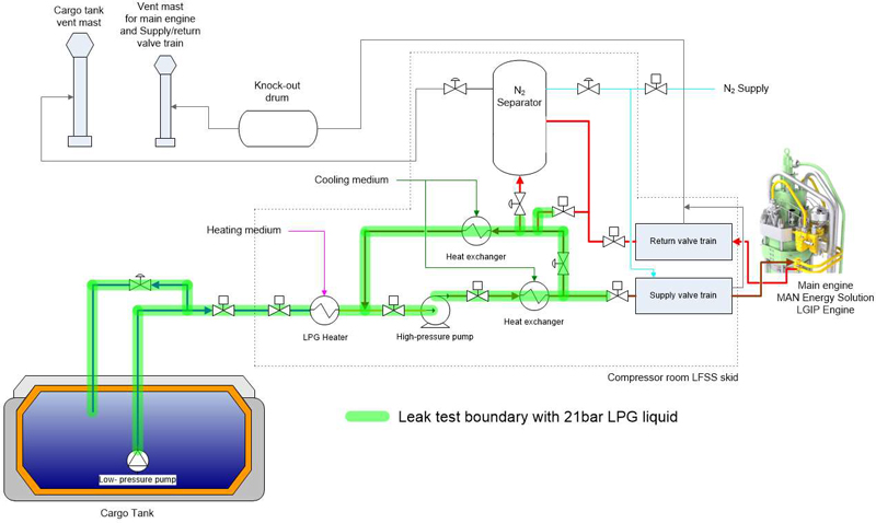
At this pressure, the LPG will be introduced to the LFSS skid and it will be confirmed all flange points, fittings, valves, and equipment in the skid with 16 bar pressure. To prevent dry turning of HP pump mechanical seal, it is recommended to open the suction valve once the skid pipelines leading up to the HP suction valve are pressurized to 21 bar, and then fill the LPG liquid to the LFSS skid for sure. This stepped leak test covers the system from the cargo tank side to the LFSS skid as highlighted in Figure 6.
3.4 N2 Separator LPG Filling
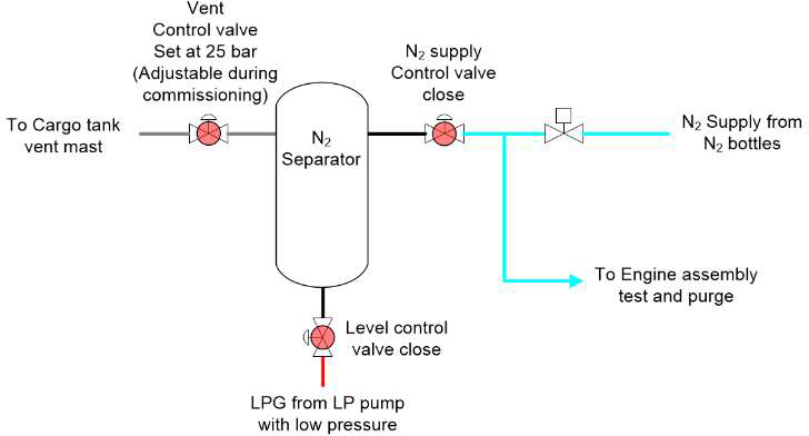
Upon completion of the LPG leak test at 21 bar pressure, the level of the N2 separator must be filled to the design-set value, which is approximately 40% of the capacity. Figure 7 depicts the valve line-up configuration prior to introducing LPG into the N2 separator. This configuration includes a closed-level control valve, closed N2 supply control valve, and closed vent control valve with an automatic control set at 25 bar.
To prevent N2 backflow to the HP pump side, which can lead to pump pressure hunting or mechanical seal damage, it is advisable to close the N2 supply control valve before opening the level control valve and introducing LPG into the N2 separator.
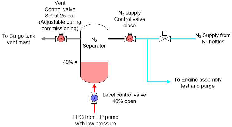
Furthermore, the vent control valve was kept closed during the filling of the N2 separator in order to avoid unnecessary LPG venting, which is uneconomical and harmful to the environment. The simulation confirmed that the LPG filling of the N2 separator was processed without venting and that the separator reached 40% capacity, as shown in Figure 8.
Once the level in the N2 separator reaches 40%, the level control valve must be closed, and the set point of the vent control valve must be adjusted to 25 bar. In this configuration, the N2 supply control valve should be switched to automatic control at a set point of 23 bar, as shown in Figure 9. Subsequently, N2 is gradually introduced, preparing the N2 separator for LFSS operation.
3.5 Overall Flow Chart for Initial LPG Filling
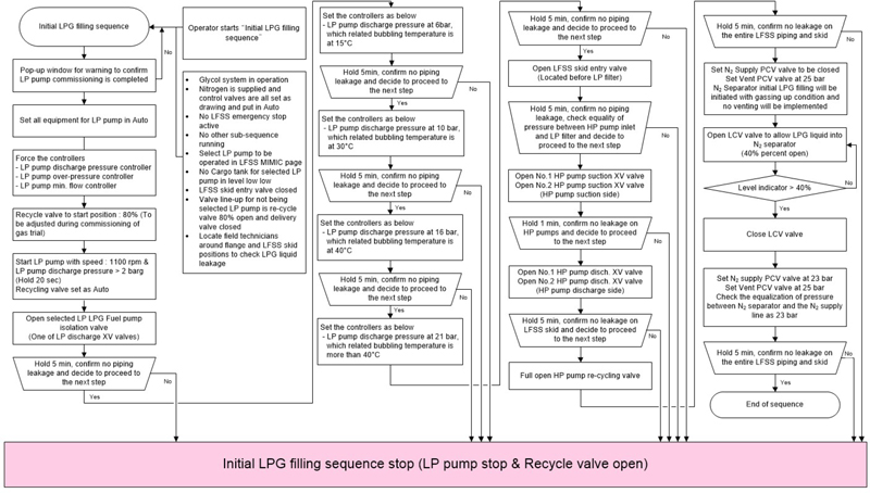
The steps involved in the initial LPG filling sequence are illustrated in Figure 10 as a flow chart. The flowchart was thoroughly examined using Aspen HYSYS to assess its applicability in commissioning and operating LFSS. It is assumed that the LP pump commissioning is complete and that the glycol system is ready. To prevent the initiation of the initial LPG filling sequence without LP pump commissioning, a pop-up warning is issued to confirm whether LP pump commissioning is finalized. After confirmation, the sequence proceeds with the automatic start of the LP pump, Owing to the empty pipelines during the initial start-up, the LPG is initially filled at relatively low RPM up to the skid. The pressure in the lines near the skid equalizes with the pump discharge pressure; therefore, the LP pump discharge pressure is set at 6 bar, and a leak test at this pressure is performed by the commissioning technicians. Each step of the leak test is preset for 5 min. If no leaks are detected during this time, the technicians can proceed by clicking “Yes” in the prompted window. Leak tests at higher pressures must be performed according to the flow chart until the pressure of 21 bar is reached.
After confirming that there are no leaks in the pipelines from the cargo dome to the skid inlet valve, an open command is provided to the skid entry on-off control (XV) valve to allow the introduction of LPG into the skid. Prior to opening this valve, the glycol system operations must be appropriately functioning so as to meet the HP pump suction requirements. Subsequently, the LPG flows into the HP pump upon opening the inlet and outlet valves along with the pressure control valve (PCV) control for the recycling pipelines.
The N2 separator is then filled with LPG after ensuring appropriate N2 supply control valve settings and venting valve manipulation, in accordance with the sequence flow requirements. When the liquid level in the N2 separator exceeds 20%, the level control valve (LCV) is closed to complete this sequence. The N2 supply should be maintained at a setting point of 23 bar, and the venting set point should remain at 25 bar. Once N2 is added to the N2 separator and the set points are satisfied, the initial LPG filling sequence is completed. This implies that the HP pump can now be operated to supply LPG to the LGIP engine.
4. Simulation Modeling and Analysis of Flow Chart Steps using ASPEN HYSYS
4.1 Initial LPG Filling Sequence
The flowchart of the initial LPG filling sequence depicted in Figure 10 was implemented using Aspen HYSYS, as illustrated in Figure 14. The simulation consists of three groups of component lists. The first group comprises combined components, such as propane, i-butane, n-butane, ethane, N2, H2O, and glycol. The second and third groups consist of glycol and H2O combination and H2O alone, respectively. In the LPG section of the simulation, the Peng–Robinson equation was employed as the fluid property package. A glycol package was selected as the fluid package for the LFSS. ASME steam properties were utilized for modeling H2O.
Prior to performing the dynamic simulation, it was necessary to input the conditions of the cargo tank, streams, pumps, heat exchangers, control valves, their control settings, and N2 separator. During the simulation of the initial LPG filling sequence, emphasis was placed on devising an effective method for conducting leak testing and safely charging the N2 separator. The selection of pressure levels for the leak test was based on a step-by-step verification process. Further, vaporization was considered even at relatively high outdoor temperatures.
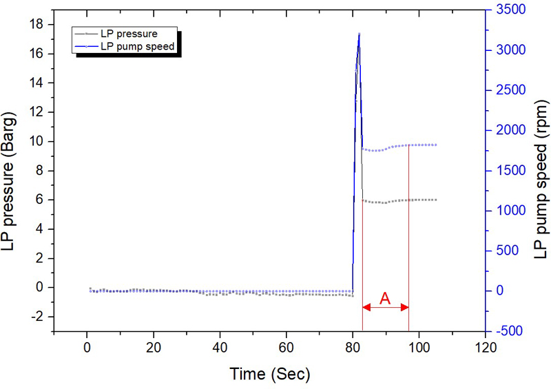
The pressure steps for the leak test were determined and analyzed by examining the pressure drops during the introduction of LPG into the empty pipelines and LFSS skid, as shown in Figure 11. The responsiveness of the control valves can be monitored by observing the LP pump RPM and its corresponding discharge pressure graph, and the time required for pressure restoration after a drop must be ascertained. The simulation tool allowed for the comprehensive monitoring of the pressure and temperature at each step, enabling the establishment of an optimal initial filling sequence.
Furthermore, the LPG filling process was simulated using Aspen HYSYS to determine the optimal configuration for achieving a stable filling speed while minimizing LPG gas venting. Specifically, during the simulation of the N2 separator filling sequence, closing the nitrogen supply valve before opening the LCV valve streamlined operations and eliminated the risk of N2 backflow into the suction of the HP pump.
4.2 Initial LPG Filling of LP Section and LFSS Skid
At the gas terminal, the LPG line from the cargo tank to the LFSS skid was gassed up with 0.3 bar pressure, and N2 is replaced by warm LPG in gaseous form. The gassing-up condition was simulated by opening valve XV of the LP pump outlet after setting the cargo tank pressure to 0.3 bar. Subsequently, the cargo tank pressure was returned to its original value (0.15 bar, which represents the normal operating pressure of the cargo tank when the LFSS is operational.
The sequence began with the operation of the LP pump and recycling section. While the XV valve for the LPG LP system remained closed, the LP pump was operated with an initial pressure setting of 6 bar, causing all LPG flow to be directed toward the LP recycling valve.
Subsequently, the pressure gradually increased to 21 bar, according to the steps outlined in Figure 5. During the initial start-up of the LP pump, it is recommended to slowly open the discharge XV valve to prevent trip events. To ensure a smooth start-up and avoid potential issues, simulations were performed to determine the optimal valve conditions and timing for LPG filling in the pipelines. The simulation results are presented in Figure 11.
Evidently, the pressure drop upon opening the XV valve is minimal, as indicated by “A” section in Figure 11. Consequently, manual control of the control valve is unnecessary during the initial LPG filling of the LP pipelines. The simulation showed successful filling of the line with LPG without any trips to the LP pump. The specific conditions for this process included having the recycling valve in the auto position, opening the discharge XV valve, and controlling the LP line pressure by using an LP pressure control PID up to 21 bar. The duration for which the LPG filled the LP line was approximately 10 s.
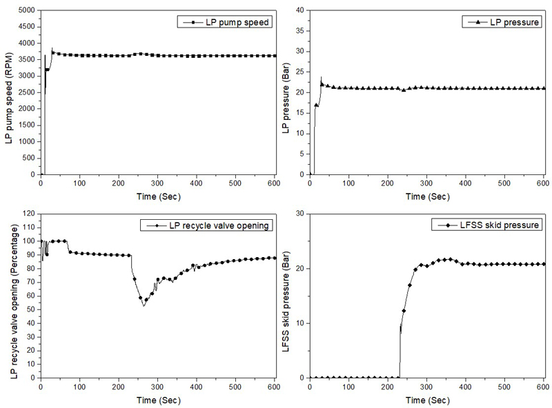
Once the LP lines stabilized, maintaining a pressure of approximately 21 bar, the XV valve for the LFSS skid entry was opened to fill the skid with LPG. Prior to opening the valve, both glycol pump and system must remain operational in order to heat the LPG from -40 °C to approximately 25 °C. Following the opening of the XV valve for LFSS skid entry, the closure of the recycle valve on the LP pump directed the LPG flow toward the LFSS skid, while increasing the LP pump RPM to meet flow demands. In the simulation, it took approximately 3 min to fill the LPG in the LFSS skid. Figure 12 shows the major parameters of the LP pump speed, LP pressure, LP recycle valve opening, and LFSS skid pressure. As evident from the graphs, the variation and related time to pressurization of the LFSS skid pressure were controlled by the LP recycle valve, whereas the LP pump was operational with responsive RPM and pressure.
The exact valve opening and duration may vary depending on the piping size and LFSS equipment design; however, this simulation serves as a valuable tool for understanding the process values during commissioning and helps prevent unnecessary equipment trips.
4.3 Initial LPG Filling Sequence in N2 Separator Section
Once the LPG completely filled the skid, including the HP system, at a pressure of 21 bar, the N2 separator must be filled to a level between 30% and 40% by opening the LCV valve. To minimize unnecessary venting, the control valves for the N2 supply, venting system stem, and N2 separator pressures were set as follows:
- - N2 separator pressure : 0.3 bar (gassing up condition with warm LPG in gaseous form)
- - N2 supply control valve : Fully closed
- - Venting control valve : Set at 25 bar
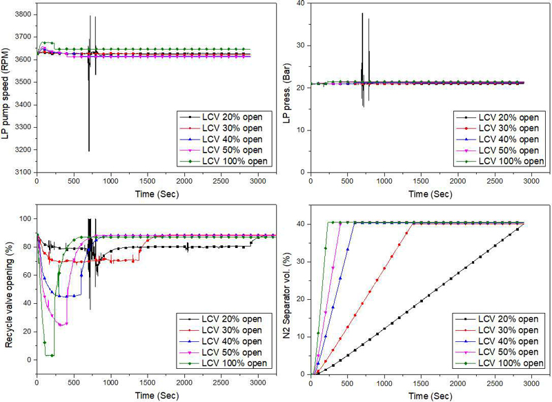
Under appropriate gauge settings in the alarm monitoring system of the ship, such as the level range and other parameters, simulations were performed to determine the time required for filling when opening the LCV valve and to monitor the condition of the N2 separator under these conditions. The tested opening percentages of the LCV valves were 20%, 30%, 40%, 50%, and 100%. The fully open condition was tested solely to assess the system response in case of operator error.
Thus, various parameters were obtained, as depicted in Figure 13. The main focus was on promptly stabilizing the LP and LFSS after opening the LCV valve, while ensuring that vaporization did not occur when the valve was excessively wide. Additionally, understanding the rough filling times helps evaluate the level gauge working conditions during actual LPG filling in gas trials. The simulation results indicated instability under the condition of 20% LCV openness at the initial stage of LPG filling because of the insufficient flow of the subcooled LPG through the LPG heater, as shown in Figure 13. To accurately acquire data on the LPG filling times, it was necessary to adjust the supply temperature of seawater for the glycol system, which was not originally included in the initial LPG filling sequence. Approximately 48 min were required to fill 40% of the N2 separator with the LCV open at 20%. Not only does the LPG filling take a long time, but there is also instability in the LPG pressure and temperature control owing to the low amount of LPG flow. Therefore, it is not recommended to handle the N2 separator with 20% valve opening during filling. The filling time was shortened with wider valve opening up to 50% LCV open. For stability and efficient filling time, it is recommended to set up the valve at 40% LCV open when filling the LPG into the N2 separator.
The simulation also included testing an operator error scenario in which the LCV valve was fully opened (100%). The simulation indicated a relatively stable LPG filling trend. However, it is desirable not to fully open the LCV valve because of the risk of failure caused by the excessive flow of LPG, which hinders the control of the pressure and temperature within the glycol system.
No adverse symptoms were observed during the simulations; however, actual equipment commissioning should include testing for any potential adverse effects caused by the speed of filling tanks with LPG. Once the levels reach approximately 40%, the LCV valve should be closed, followed by N2 supply at approximately a 23 bar set point and maintaining the venting pressure at 25 bar to relieve any pressure spikes occurring during commissioning and operation. Figure 14 shows the LFSS dynamic model flowsheet established in HYSYS.
5. Validation of the Simulation Modeling
5.1 Simulation Data Validation during Gas Trial
The optimized steps of the initial LPG filling sequence were examined through manual operation of the LFSS during the gas trial of the LPG DF vessel. The process begins with a step-by-step leakage test after the LP pump is commissioned.
In the first step, the LP pump was started with the recycling valve opened, allowing a minimal subcooled LPG flow to the entry point of the LFSS skid for leak testing. HYSYS simulation was used to estimate the time required for this sequence, and the actual LPG filling took approximately a few seconds, which is similar to the simulation results. As several leaks were detected in the lines, having a function that displays the time for each step during leak testing and stops the LP pump when an operator selects “No” button proved to be a useful tool in preventing major gas leaks. Under normal conditions without any leakage, a 5-min holding time at a specific pressure of up to 21 bar for leak testing may be considered excessively long. However, performing soap bubble tests on multiple checkpoints within the LFSS skid, such as pressure and temperature sensors, flanges, valves, and equipment within the LFSS skid requires additional time. Consequently, an extended holding time for leak testing of the LFSS skid was incorporated into the sequence.
Once the leak test of the pipelines and the LFSS skid with 21 bar of LPG was completed, the sequence for filling the N2 separator with LPG was verified manually. The nitrogen supply control valve was set in a fully closed position to prevent nitrogen backflow into the suction of the HP pump. The vent control valve pressure setting should be less than 10 bar, allowing the LPG to be introduced into the N2 separator when the LCV valve is opened, while some of the LPG vaporizes and is vented out through the vent mast.
Using the Aspen HYSYS process simulator, the duration for filling up to 40% of the volume in the N2 separator was measured and found to be approximately 10 min. However, as shown in Figure 13, the actual testing took approximately 7 min under identical setup conditions to the HYSYS modeling. The difference between the HYSYS simulation and actual testing could be attributed to variations in the outdoor temperature in the compressor room where the LFSS skid was located, as well as differences in the control valve responsiveness and slight opening percentage offsets compared to the actual valves. This simulation and related understanding of the estimated time for LPG filling the N2 separator proved to be useful for cross-checking the conditions and performance of the level transmitter attached to the N2 separator tank.
Each step of the initial LPG filling sequence was examined and validated through manual operation of the LFSS. The results indicate that the values obtained from the Aspen HYSYS simulation are highly accurate in predicting actual equipment operation, considering variations in external temperature conditions.
5.2 Study of Leak Test Length per Steps in Actual Gas Trial Circumstances
If leak points exist in LFSS pipelines, a longer duration is required for the leak test. However, for a smooth commissioning process, a 5-min leak test proved sufficient to verify the line leakage. During the actual gas trial of the LPG carriers, each section of the leak test described in Figure 6 required less than 5 min, except for the first step of the LP section with a 6 bar leak test. This extended duration was because of the loose flange connection on the check valve.
5.3 Filling LPG into the N2 Separator: Comparison between Simulation and Actual Equipment Operation during Gas Trial
As indicated by the simulation data for filling the N2 separator with LPG, opening the LCV valve to 40% resulted in a stable performance of the LP pump and responsive behavior of the recycle valve. Additionally, it allowed for a considerable filling time for the N2 separator. The actual duration of filling with the LCV valve opened at 40% was approximately 7 min, and there were no signs of vaporization or excessive pressure drop from the LP system.
5.4 Verification of Simulation by LFSS Manual Operation
The LPG filling sequence, depicted in Figure 10 and studied using Aspen HYSYS, was manually executed during the gas trial of the LPG carrier (LPGC). Each step of the sequence performed well, and no systematic issues were encountered during the operation of the LFSS for leak testing and LPG filling.
5.5 Summary of Simulated Data and Actual Data obtained from the Experiment during Gas Trial
During the initial LPG filling manual operation in Figure 10, the summary table featured in Table 2 was created as reference data to facilitate the system operation.
In the cases of LP pipeline LPG filling and LFSS skid LPG filling, the values obtained were similar to the simulation values. For the N2 separator LPG filled with a 40% open LCV valve, there was a 2-min difference in the filling time compared to the simulation value. This difference can be attributed to a slight variation in the manufacturing of the cage in the control valve, which resulted in a discrepancy between the actual flow coefficient (Cv) and the designed value. However, this information is valuable for understanding the approximate timing of filling the target N2 separator. During the initial LPG filling sequence, the LP pump RPM and recycle valve responsiveness were stable, which is consistent with the simulation results.
6. Conclusion
This study entailed HYSYS simulations of a stepped sequence for initially filling LPG into the pipelines and fuel skid package of an LFSS and related experiments to investigate the efficiency and accuracy of the simulation model. Additionally, the potential application of the sequence to LPG DF vessels was investigated, including an assessment of its associated advantages and disadvantages. The findings from both the simulation and actual operation indicate that operating the system with an optimized sequence that considers various LPG properties can significantly enhance the stability as compared to manual operation based solely on personal experience.
Unfortunately, the initial LPG filling sequence was not implemented in the alarm monitoring system of the ship; instead, it was only compared manually using the data obtained from the simulations. However, the manual operation closely followed the sequential steps outlined in Figure 10, providing sufficient evidence to demonstrate that the initial LPG filling sequence was beneficial for efficient commissioning and establishing a reliable system setup.
One concern associated with this sequence is the potential for errors due to network malfunctions or unexpected sequencing issues. However, these concerns can be addressed by reinforcing reset functions and implementing system stops whenever any sequential order malfunctions are detected.
Despite these concerns, utilizing the initial LPG filling sequence is essential to avoid accidents resulting from clumsy system operations. Moreover, it is advantageous for reducing commissioning time during gas trials and facilitating long-term maintenance even after ship delivery or during dry-docking events.
Future work will focus on integrating the initial LPG filling sequence into the ship alarm monitoring system and analyzing its efficiency for shipyard engineers and seafarers.
Acknowledgments
Writing this paper would have been very difficult without assistance from Mr. Jaewook Son. I express my gratitude to him (R&D Center, Korea Shipbuilding & Offshore Engineering).
Author Contributions
Conceptualization, S.M.Jeong; Methodology, J.W.Son; Software, J.W.Son; Formal Analysis, S.M.Jeong; Investigation, S.M.Jeong; Resources, S.M.Jeong; Data Curation S.M.Jeong; Writing-Original Draft Preparation, S.M.Jeong; Writing-Review & Editing, J.G.Nam; Visualization, S.M.Jeong; Supervision, J.G.Nam
References
- IMO, http://www.imo.org/en/MediaCentre/PressBriefings/pages/IMO-agrees-possible-outline-for-net-zero-framework.aspx, , Accessed July 25, 2024
- MAN Energy Solutions, https://www.man-es.com/marine/products/planning-tools-and-downloads/technical-papers/2, Accessed May 5, 2024
- S. Han, H. -S. Kim, B. -U. Han, and D. -J. Lee, “Review on the fuel supply system of ME-LGIP engine for LPG pro-pulsion VLGC,” Bulletin of the Society of Naval Architects of Korea, vol. 56, no. 4, pp. 10-14, 2019 (in Korean).
-
L. Zhou, W. Shi, W. Lu, B. Hu, and S. Wu, “Numerical investigations and performance experiments of a deep-well centrifugal pump with different diffusers,” Journal of Fluid Engineering, vol. 134, no. 7, 2012.
[https://doi.org/10.1115/1.4006676]

-
F. Zhang, M. Bohle, and S. Yuan, “Experimental investiga-tion on the performance of a side channel pump under gas-liquid wo-phase flow operating condition,” Journal of Pow-er and Energy, vol. 231, no. 7, pp. 645-653, 2017.
[https://doi.org/10.1177/0957650917713090]

- Thermal analysis of vessels with tanks for liquefied gas, ABS guidance notes, pp. 8-9, September 2019.
-
Wang, Cheng, et al. “Transient performance study of high pressure fuel gas supply system for LNG fueled ships.” Cryogenics 125 (2022): 103510.
[https://doi.org/10.1016/j.cryogenics.2022.103510]

- N. B. Chowdhury, Pressure-Temperature Diagram Analysis of Liquefied Petroleum Gas and Inspection of Retrograde Phenomenon, Advances in Pure and Applied Chemistry (APAC)-Vol. 1, 2167-0854, 2013.
-
N. Bariha, V. C. Srivastava, and I. M. Mishra, “Theoretical and experimental studies on hazard analysis of LPG/LNG release: a review,” Reviews in Chemical Engineering, vol. 33, no. 4, pp. 387-432, 2017.
[https://doi.org/10.1515/revce-2016-0006]


