Resonant frequency tuning of wave energy converters using variable moment of inertia
Copyright © The Korean Society of Marine Engineering
This is an Open Access article distributed under the terms of the Creative Commons Attribution Non-Commercial License (http://creativecommons.org/licenses/by-nc/3.0), which permits unrestricted non-commercial use, distribution, and reproduction in any medium, provided the original work is properly cited.
Abstract
In this study, a novel tuning method for the resonant frequency of a yo-yo vibrating system is proposed. Because the period of the real ocean is continually changing, the tuning capability of resonant wave energy converters is crucial for enhancing the efficiency of electricity production. A variable moment of inertia (VMI) device is first introduced and utilized to change the resonant frequency of a yo-yo vibrational energy harvester. Numerical analysis of the VMI device is then performed to determine the influence of each VMI parameter, and an experimental setup is constructed and tested. The experimental measurements match the theoretical frequencies with an accuracy of 8%. The frequency-tuning range of the experimental model is found to be 11% of the largest resonant frequency at the lowest position of the VMI device. The results show that the proposed method is applicable to wave energy harvesting.
Keywords:
Resonant frequency, Yo-yo vibrating system, Variable moment of inertia, Wave energy1. Introduction
Wave energy is a type of marine energy that primarily exists on the sea surface. It is reported that 2000 TWh of electricity can be produced annually after the commercial development of wave power generation [1]. Among the wave energy technologies, oscillating body or moving body wave energy converters (WECs) have the largest number of prototypes. These converters utilize a floating or submerged buoy that moves relative to the wave input. State-of-the-art oscillating body WEC technologies for maximizing the harvested energy can be found in [2]. In an oscillating body WEC, two resonant phenomena exist: resonance of the buoy caused by the wave input and that of the inner vibrating system due to the buoy motion. The former has been actively investigated and applied in many prototypes, whereas the latter has remained in the research stage. Choi and Kweon [3], Cho et al. [4], and Han and Lee [5] proposed the concept and conducted a numerical study of a resonant WEC with inner vibrating systems. The yo-yo vibrational energy harvester was first proposed by Jang et al. [6]. It can convert the translational displacement of the proof mass into rotational displacement of the reel, and its resonant frequency can be varied by changing the radius of the reel. It is advantageous for low-frequency vibrational energy harvesting, such as sea-wave oscillations. A detailed study of the yo-yo vibrational energy harvester applied to a WEC can be found in [7].
Because the wave period varies consistently, the tuning capability of a resonant WEC with an inner vibrating system to the input wave frequency is crucial for its efficiency. In this study, we proposed a geometrical frequency-tuning method using a variable moment of inertia (VMI) device. The proposed device was investigated by numerical calculations and verified experimentally.
2. Yo-yo vibrational energy harvester with VMI
2.1 Modeling
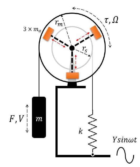
A schematic of the yo-yo vibrating system is illustrated in Figure 1. The proof mass and spring are connected to the reels by wires, and the translating motions of the proof mass and spring are converted to rotation of the reels. The radii of the reels are denoted as rm and rs , respectively. When the stiffness of the spring is k and the proof mass is m, the impedances of the translating and rotating parts can be respectively given by
| (1a) |
| (1b) |

Schematic of the proposed yo-yo vibrational energy harvester with a variable moment of inertia device
where F and V are the excitation force on the proof mass and its velocity, respectively; τ and Ω are the torque applied to the reel axis and its rotational velocity, respectively; c is the damping coefficient; J is the integrated moment of inertia of the rotating part; and ω is the base excitation frequency. Because τ = rmF and V = rmΩ, the impedance in Equation (1a) can be expressed as
| (2) |
The total impedance of the system can be obtained from the parallel connection of Equations (1b) and (2), as follows:
| (3) |
When the amplitude of the excitation is Y , the excitation torque at the proof mass is τ = −mrmYω2sinωt. Substituting it to Equation (3), the rotating speed of the reel can be expressed as follows:
| (4) |
The undamped resonant frequency f in which the rotating speed reaches its maximum value can be obtained from the denominator of Equation (4):
| (5) |
where T is the period and γs = rs⁄rm. The resonant frequency of the yo-yo vibrating system can be modulated via a geometric parameter γs and the stiffness-to-mass ratio.
2.2 VMI
The resonant frequency in Equation (5) can be further modified using the integrated moment of inertia of rotating part J. The VMI device, as shown in Figure 1, can be realized. Three auxiliary masses ma are attached to the mass reel. When their distances ρ from the center are identical, the integrated moment of inertia can be rewritten as
| (6) |
where n is the number of auxiliary masses and J0 is the moment of inertia of the reel assembly. The resonant frequency with VMI can then be derived from Equation (5) by substituting Equation (6):
| (7) |
where n is the total number of auxiliary masses and γa = ρ⁄rm. In Equation (7), the resonant frequency can vary with the geometric parameter γa. In field applications, it is difficult to change the resonant frequency from the constituent parameters, that is, m, k, and the ratio of the two reels, γs. Thus, the introduction of a VMI device can be a good choice for tuning of resonant wave power generators.
2.3 Property
The performance of the VMI device can be measured by using the ratio of the two resonant frequencies of the yo-yo vibrating system with and without VMI. For simplicity, let J0 = 0, which yields
| (8) |
where . Figure 2 illustrates the frequency ratios for μ and γa, which show that the resonant frequency can be reduced when both the total mass of the auxiliary masses and distance ρ increase. In Figure 2, the frequency ratio variance of the mass ratio decreases slightly when μ changes from 0.1 to 0.5, whereas that of γa increases when γa changes from 0 to 1. Thus, geometrical tuning by manipulating the distance between auxiliary masses is more efficient for the VMI device.
3. Experiment
3.1 Implementation
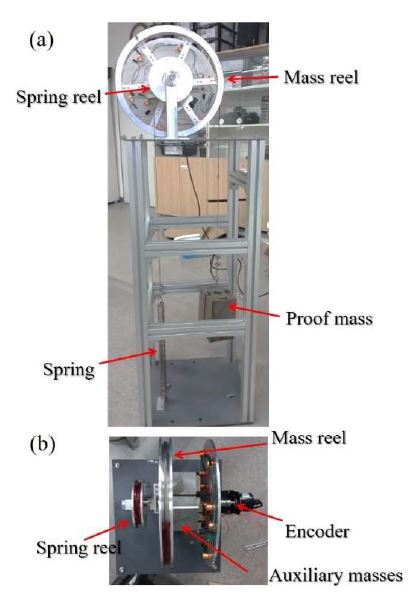
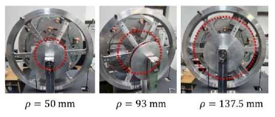
A yo-yo vibrating system with a VMI device was fabricated, as shown in Figure 3. Iron wires are wound around the reels and connected to the spring and proof mass, respectively. The two reels are fixed to the shaft and their rotational displacements are recorded by an encoder (AUTONICS E50S8-100-3-T-1). The physical parameters of the experimental setup are listed in Table 1. The implementation of the VMI is shown in Figure 4. Three auxiliary masses are attached to the mass reel at three positions. The distance ratios (γa) are 0.32, 0.60, and 0.89. The resonant frequencies were then calculated as 0.65, 0.62, and 0.58 Hz for the three positions of the VMI device based on the parameters in Table 1 using Equation (7). These frequencies correspond to the periods of 1.56, 1.61, and 1.72 s, which are often found in shallow seas. This result also shows that the maximum frequency change is 10.7% of the largest resonant frequency at the lowest position of the VMI device.
3.2 Experimental validation
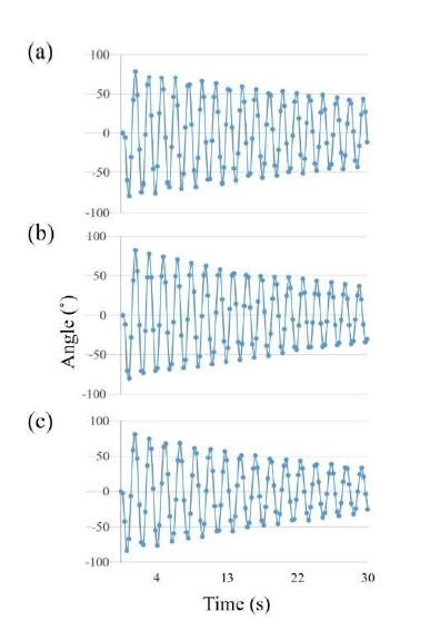
To determine the resonant frequency of the yo-yo vibrating system with VMI, we pulled and released the proof mass. The vibrational motions of the reels were recorded for 30 s by the encoder and PXI system of National Instruments. The experimental results are shown in Figure 5. The measured frequencies obtained from the numbers of oscillations divided by the elapsed times are 0.61, 0.57, and 0.54 Hz, respectively, when the distances are 50, 93, and 137.5 mm. The differences between the numerical calculations are 6, 8, and 7%, respectively. These errors are attributed to the inertias of the neglected parts, for example, wires, and enlargement of the effective radius of the reels owing to the winding. The frequency change range from the experiment is 11.5%, which is similar to that of the numerical calculation.
4. Conclusion
In this study, we introduced a frequency-tuning device for the yo-yo vibrational energy harvester. The proposed device can change the resonant frequency by 11% from the original value. The device performance and properties were also studied. The proposed device can be a practical solution for tuning resonant WECs.
Acknowledgments
This research is the result of receiving the support for the university innovation support project and supported by “ (RIS)” through the National Research Foundation of Korea (NRF) funded by the Ministry of Education(MOE)(2021RIS-004).
Author Contributions
Conceptualization, S. -J. Jang; Methodology, S. -J. Jang; Formal Analysis, S. -J. Jang; Investigation, S. -J. Jang; Data Curation B. -R. Kim; Writing-Original Draft Preparation, S. -J. Jang; Writing-Review & Editing, S. -J. Jang; Project Administration, S. -J. Jang; Funding Acquisition, S. -J. Jang.
References
- D. H. Jung, “Wave Power Generation – Market Perspectives and Strategies,” KISTI Market Report, pp. 20-23, 2012 (in Korean).
- J. V. Ringwood, G. Bacelli, and F. Fusco, “Energy-maximizing control of wave-energy converters,” IEEE Control Systems Magazine, pp. 30-55, 2014.
-
I. -H. Choi and H. -M. Kweon, “Extraction of wave energy using the coupled heaving motion of a circular cylinder and linear electric generator,” Journal of Ocean Engineering and Technology, vol. 25, no. 6, pp. 9-16, 2011 (in Korean).
[https://doi.org/10.5574/KSOE.2011.25.6.009]

-
Y. H. Cho, C. J. Lee, and D. S. Hong, “Dynamic design of a mass-spring type translational wave energy converter,” Journal of the Korean Society of Manufacturing Technology Engineers, vol. 21, no. 1, pp. 182-189, 2012 (in Korean).
[https://doi.org/10.7735/ksmte.2012.21.1.182]

-
K. B. Han and H. W. Lee, “The research of wide band vibration energy harvester using ocean wave,” Journal of the Korean Society of Marine Engineering, vol. 37, no. 6, pp. 596-602, 2013 (in Korean).
[https://doi.org/10.5916/jkosme.2013.37.6.596]

-
S. -J. Jang, I. H. Kim, H. J. Jung, and Y. P. Lee, “A tunable rotational energy harvester for low frequency vibration,” Applied Physics Letters, vol. 99, no. 13, 134102, 2011.
[https://doi.org/10.1063/1.3644130]

-
S. -J. Jang and B. -R. Kim, “Study on the yo-yo vibrational energy harvester applied to the wave power generation,” Transactions of Korean Society of Noise and Vibration Engineering, vol. 31, no. 4, pp. 383-389, 2021.
[https://doi.org/10.5050/KSNVE.2021.31.4.383]


