A study on characteristics of the ship resistance for the 19-ton class airboat
Copyright ⓒ The Korean Society of Marine Engineering
This is an Open Access article distributed under the terms of the Creative Commons Attribution Non-Commercial License (http://creativecommons.org/licenses/by-nc/3.0), which permits unrestricted non-commercial use, distribution, and reproduction in any medium, provided the original work is properly cited.
Abstract
The current application of airboats in domestic fields is mainly for military or police purposes. In several other countries, airboats have been widely used, as they are common in various fields, such as military, leisure, tourism, and rescue. Recently, interest in airboats, which have been widely applied in various fields such as environmental management, leisure, search, and rescue, has been increasing in domestic fields. Preliminary research on airboats is proceeding steadily in small companies and universities. In this study, the effective power estimation of a 19-ton class airboat was performed using empirical formulae for the planing hull using MAXSURF software, which is widely employed in the basic design of small-sized ships. The results of the effective power estimation were compared with those of the model test, and an effective power estimation most suitable for the hull characteristics of the airboat was determined. The wave pattern analysis was performed based on MAXSURF’s strip theory to examine the wave pattern characteristics and compared them with those of the model test. This study is intended to be used as a basis for future airboat research and development.
Keywords:
Airboat, MAXSURF, Model test, Effective Power Estimation, Wave pattern1. Introduction
The airboat is propelled by the principle of action and reaction in Newton's motion laws, as well as the lifting force generated by the air flow along each airfoil surface of the propeller rotating at high speed.
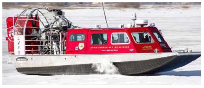
The air thrusters of an airboat are generally located on the stern side of the deck of the airboat because of various causes such as visibility, maneuverability, noise, and vibration, as shown in Figure 1 [1].
In the current status of domestic R&D research on airboats, a few cases have been conducted for military or police ships in special fields. However, in several other countries, airboats are very common in various fields such as military, leisure, tourism, and rescue.
Recently, interest in facilitating airboats into various fields such as environmental management, leisure, and search and rescue has been increasing in Korea, and domestic small- and medium-sized companies and universities have been focusing on basic research on airboats [1][2].
In this study, the airboat considered was a small-sized rescue boat that can be accessed and operated in both sea and tidal or mud flat regions, and was developed for search and rescue missions by quickly accessing the location of isolated rescuers.
In general, based on the Froude number = 1.0, the boat is divided into planing and non-planing hulls, and hydrodynamic characteristics such as drag and lifting vary depending on the hull and geometric characteristics [3][4]. Depending on the boat speed and environmental conditions, the motion and drag performance are determined by the running attitude, such as lifting force, trim angle, and wetted surface length.
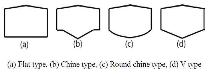
Typical sectional shapes for general boats include flat type, chine type, round chine type, and V-type and the body shapes of boats are in general determined in accordance with the characteristics of the boat operation. A variety of conceptual bodies for general boats is presented in Figure 2.
In this study, the airboat considered has a flat-type body with a flat bottom and slanted on both sides that are easy to operate in harsh environments, such as shallow water and tidal flat regions, and is particularly effective for sliding on tidal flats.
A boat with a flat bottom is known to have an increased lifting and trim angle compared to conventional V-type boats [5]. That is, when the deadrise angle decreases, the lifting force and trim angle increase, and the boat resistance decreases as the wetted surface area decreases [6]. Although the resistance component is somewhat reduced, the fluid impact, such as slamming and bow flare phenomenon, dramatically increases, especially in flat surfaces and bodies, which induce vibrations and noises. In addition, if the fluid impact increases, there is a probability that it may cause an increase in the transient response of the boat, which may cause deterioration in maneuverability and operability.
Studies have been conducted to estimate preliminary ship resistances using various methods, such as empirical formulae, model tests, and computational fluid dynamics (CFD) [7][8].
There has been no study conducted on resistance estimations by empirical and analytical methods as well as model tests for airboats with flat-type body, which further emphasizes the necessity of this study.
Kim et al. [7] compared the Savitsky resistance estimation with the model test results for four types of planing hulls and in the case of a non-prismatic hull, the running attitude and resistance estimation calculated from the empirical method showed a big difference from those of the model test. Oh and Yoo [9] estimated the running attitude of a high-speed planing hull through numerical analysis using a 3D panel method. Utama et al. [10] compared both Savitsky’s empirical method and the CFD method with the model test for three types of planning hulls, which showed that the CFD method was close by the range of approximately 20%, but the empirical method showed a large error range of approximately 40%.
In this study, the effective power for a 19-ton class airboat was calculated by various empirical formulae for a flat-type planing hull using MAXSURF software, which is widely employed in the basic design of small-sized ships. The calculated power estimation was compared with the model test and the most suitable estimation method for the airboat considered in this study was verified. In addition, to examine the wave pattern characteristics of the airboat, a wave pattern analysis was performed based on the MAXSURF strip theory, and the results were compared with those of the model test.
2. Airboat
The main specifications of the airboat used in this study are listed in Table 1. The airboat is a small-sized ship with about 12.8 m class and other principal dimensions are 5.4 m and 1.27 m for beam and depth respectively. The displacement of the airboat under the full load condition is approximately 19.0 tons and the maximum speed is 35 knots.
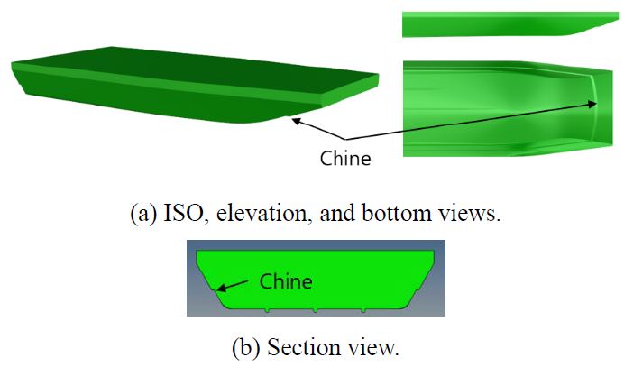
The hull structure of the airboat is shown in Figure 3. A flat bottom was applied to facilitate driving in tidal flat regions. In addition, a chine was applied to both sides to improve maneuvering performance, such as roll damping decay and vibration reduction during navigation. Moreover, the slopes were considered to the front and both sides of the airboat to improve maneuvering and seakeeping performance.
3. Power estimation and wave pattern analysis
In the basic design of small-sized ships, basic calculations, such as the effective power and resistance to select the main engine, depend on empirical formulae. In the design stage, MAXSURF, a powerful basic design software, is widely used to calculate the effective power for small-sized ships, such as high-speed boats, planing hulls, and yachts. The effective power calculations in MAXSURF provide a variety of resistance approaches using experimental and empirical formulae by Savitsky, Blount and Fox, and Wyman, for various planing hulls [11]. In this study, effective power calculations were performed using various empirical formulae in MAXSURF, and the empirical methods were reviewed.
The Savitsky method is a representative method for estimating the effective power required for planning hulls. The Savitisky method estimated the running attitude, such as the trim and wetted surface length, using basic experiments and hydrodynamic characteristics for the prismatic model and derived the resistance of the planning hull at the equilibrium state [5]. Although the Savitsky method includes numerous empirical formulae depending on experiments for the prismatic hull, there has been no attempt or approach for power or resistance estimation for flat bodies such as airboats. The Blount and Fox method modified the Savitsky method, and the selection of an effective beam and deadrise angle were considered as the dominant parameters for determining an accurate resistance and effective power calculation [8].
In this study, the analytical model of the airboat was generated to calculate the effective power and analyze the wave pattern using “Modeler” module in the MAXSURF. The model constructed was verified through hydrostatic data. Table 2 summarizes the initial input data provided to calculate the effective power and resistance in MASXSURF; the calculation was based on full load condition.
Although MAXSURF provides a variety of empirical methods by Savitsky, Blount and Fox, Wyman, and Lahtiharju for power estimation of each designated planning model, the Wyman and Lahtiharju methods were excluded from the calculations in this study, because of the difference in the hull characteristics.
The resistance calculation methods by Savitsky and Blount and Fox assumes the initial speed, performs iterative calculations to become the hydrodynamic equilibrium state corresponding to the speed and running attitude, and finally derives the effective resistance and power when a stable equilibrium state is reached. Here, the calculated effective resistance is expressed as the sum of the pressure resistance and frictional resistance, which depends on the running attitude at an average draft, as shown in Equations (1)-(3).
| (1) |
| (2) |
| (3) |
where, D : Total resistance, Dp : Pressure resistance, Df : Friction resistance, τ : Trim angle, Δ : Displacement, Cf : Friction coefficient, v : velocity, λ b2 : Viscous resistance, β : Deadrise angle
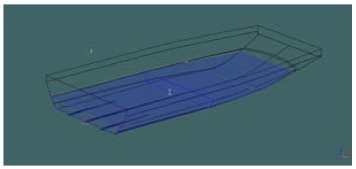
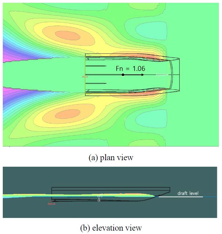
Wave pattern analysis was performed based on MAXSURF strip theory. Figure 4 shows the application of planing hull modeling for wave pattern analysis.
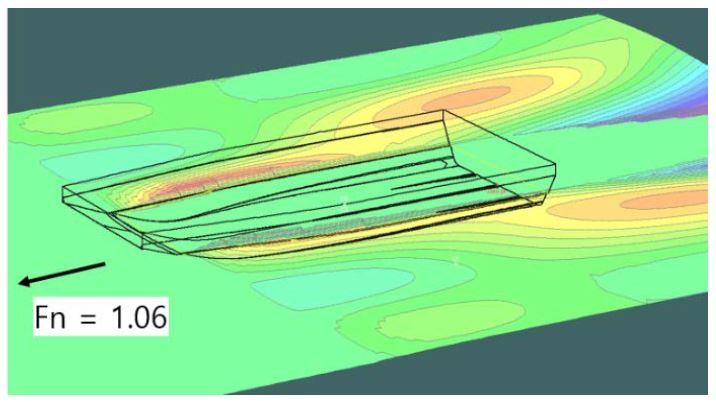
To fully understand the wave pattern characteristics in the fluid region, the fluid region was created by expanding both sides, the front, and the stern region more than twice that of the airboat. The wave pattern analysis results obtained using MAXSURF are shown in Figure 5.
The stern wave of the airboat was well maintained with the transom shape of the airboat, and the sidewalls of the stern wave were formed by sunken boat sides. The stern wave shape gradually collapsed from the sidewalls owing to gravity.
4. Model test
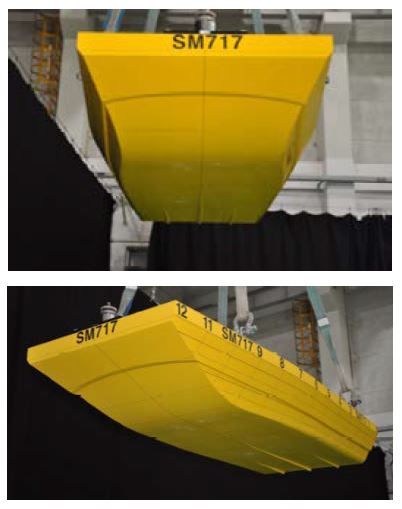
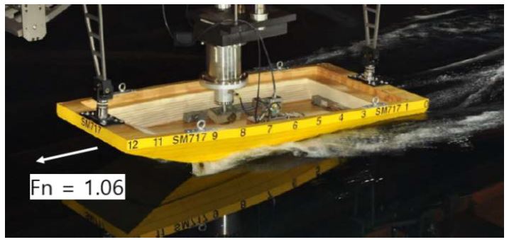
The test model was made on 1/7 scale of an actual airboat. The test loading condition was considered under full-load condition. The test model was manufactured using urethane materials, and the effective power was predicted according to the “ITTC Recommendation”. Figure 6 shows the model used in the model test. The test conditions were constrained in the surge, sway, and yaw degrees of freedom at the center of gravity of the test model, and the pitch, heave, and roll degrees of freedom were maintained free. The resistance component was measured in real time using a load cell installed at the center of gravity of the test model.
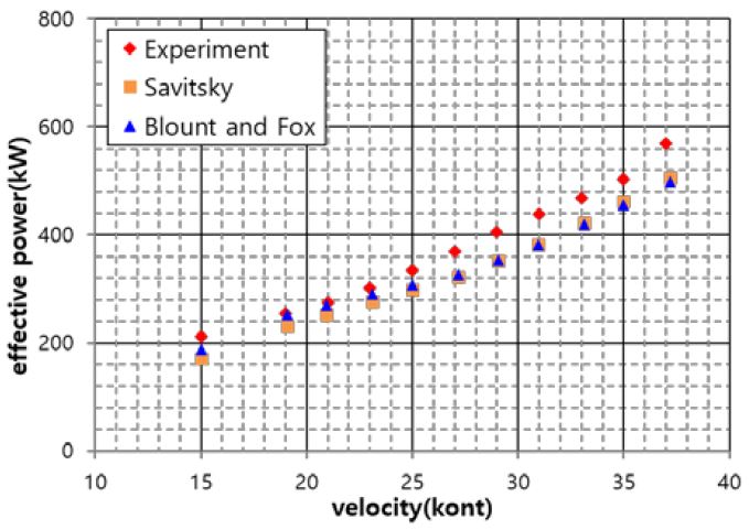
The results of the model tests are shown in Figures 7–9. Figure 7 compares the effective power results derived from the model test with the Savitsky and Blount and Fox empirical methods.
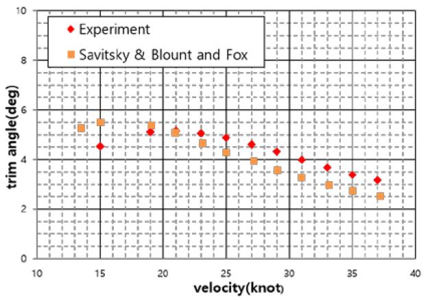
As shown in Figure 7, the considered empirical methods showed good agreement within the range of approximately 10% against the model test, compared to the error range of approximately 40% for the conventional V-type planing hull. The effective power was significantly affected by the running attitude, and the transition of the running attitude in the model test was initiated at 21 knots, as shown in Figure 8. In the high-speed region of over 21 knots, the difference in running attitudes between the model test and empirical methods deviated more than in the low speed region.
The running attitudes of the empirical methods were compared with those of the model test, as shown in Figure 8. They showed a similar tendency in running attitudes. As shown in Figure 8, in the case of the model test, the transition speed of the trim angle was clearly shown at approximately 21 knots, and the transition speed for the empirical methods was 16 knots. The body shape of the test model changed according to its front slope of the test model. The wetted surface area and lifting force at the front were relatively smaller than those at midship, which was dominantly affected in the lower trim angle and speed region. On the contrary, empirical methods were considered based on the uniform prismatic body throughout the ship length. Therefore, the transition speed of the model test relatively moved forward to the higher-speed region.
Effective power estimation is known to be affected by the running attitude, such as the length of the wetted surface, trim angle, and lifting height, and is known to fluctuate sensitively according to the running attitude.
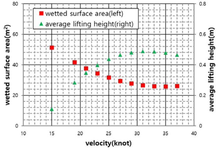
Although the Savitsky and Blount and Fox methods did not include accurate running attitudes, such as lifting and trim status according to boat speeds, the effective power estimations derived from the empirical formula were within the error range of approximately 10% compared to those of the model test. Figure 9 shows a comparison of the wetted surface area and the lifting height. As the lifting height increased, the wetted surface area exhibited a tendency to reverse perfectly.
The results of the wave pattern for the model test and analysis are shown in Figures 10 and 11, respectively. The wave characteristics of the stern and both sides of the airboat showed a similar trend in the model test and wave pattern analysis.
5. Conclusion
In this study, the effective power for a 19-ton class airboat was calculated by various empirical formulae for a flat-type planing hull using MAXSURF software, which is widely employed in the basic design of small-sized ships. The calculated power estimation was compared with the model test and the most suitable estimation method for the airboat considered in this study, was verified. In addition, to examine the wave pattern characteristics of the airboat, a wave pattern analysis was conducted based on the MAXSURF strip theory, and the results were compared with those of the model test.
The effective power estimation calculated by the empirical methods of Savitsky and Blount and Fox showed good agreement with the model test in the range of approximately 10%.Although the aforementioned empirical methods did not consider accurate running attitudes, such as lifting and trim status, according to boat speeds, it was quite encouraging that the two empirical methods showed good agreement with the model test.
Unlike the results of previous studies on planing boats, in this study, the effective power estimation of the airboat is relatively well matched because the Savitsky method is based on the prismatic hull, which is similar to the hydrodynamic properties of the flat hull.
Wave pattern analysis was performed based on MAXSURF strip theory in the steady state. The stern wave of the airboat was well maintained with the transom shape of the airboat, and the sidewalls of the stern wave were formed by sunken boat sides. The stern wave shape gradually collapsed from the sidewalls owing to gravity.
Acknowledgments
This research was conducted with the support of Korea Coast Guard R&D project “Development of a Korean all-weather rescue boat for a solitary person”
Author Contributions
Conceptualization, J. H. Pyun; Methodology, J. H. Pyun; Software, J. H. Pyun and I. T. Kim Formal Analysis, J. H. Pyun; Investigation, J. H. Pyun; Resources, H. K. Yang and J. H. Choo; Data Curation, J. H. Pyun; Writing-Original Draft Preparation, J. H. Pyun; Writing-Review & Editing, S. G. Ryu; Visualization, J. H. Pyun; Supervision, J. H. Pyun and S. G. Ryu; Project Administration, S. G. Ryu; Funding Acquisition, S. G. Ryu.
References
- S. H. Jun and J. S. Jung, “Development of an airboat with full cabin propulsion,” Proceeding of Korean Institute of Navigation and Port Research, Nov. 02, pp. 143-144, 2017.
- Development of Airboat Hulls for Viewing Operations in Coastal and Tidal Areas, Mokpo National Maritime University( MMU), 2014.
-
O. M. Faltinsen, Hydrodynamics of High-Speed Marine Vehicles, Cambridge University Press, 2005.
[https://doi.org/10.1017/CBO9780511546068]

- D. Frisk and L. Tegehall, Prediction of High-Speed Planing Hull Resistance and Running Attitude, Chalmers University of Technology Press, 2015.
-
J. M. Almeter, “Resistance prediction of planing hulls: State of the art, marine technology,” vol. 30, no. 4, pp. 297-307, 1993.
[https://doi.org/10.5957/mt1.1993.30.4.297]

-
D. Savitsky, “Hydrodynamic design of planing hulls,” Marine Technology and SNAME News, vol. 1, no. 4, pp. 71-95, 1964.
[https://doi.org/10.5957/mt1.1964.1.4.71]

-
D. J. Kim, S. Y. Kim, S. H. Kim, E. H. Seo, and S. H. Rhee, “Effects of hull form variations on resistance and seakeeping performance of planing hulls with and without incoming regular waves,” Journal of the Society of Naval Architects of Korea, vol. 51, no. 5, pp. 369-379, 2014 (in Korean).
[https://doi.org/10.3744/SNAK.2014.51.5.369]

-
B. L. Blount and D. L. Fox, “Small-craft power prediction,” Marine Technology and SNMAE News, vol. 13, no. 1, pp. 14-45, 1976.
[https://doi.org/10.5957/mt1.1976.13.1.14]

- K. H. Oh and J. H. Yoo, “A prediction on running attitude of high speed planing craft,” Journal of the Korea Ship Safety Technology Authority, no. 33, pp. 12-31, 2012.
-
I. K. A. P. Utama, I. K. Sutiyo, S. Suastika, Y. A. Hasanudin, Hermawan and W. D. Aryawan, “Resistance analysis of rescue boat in calm water condition,” IOP Conference Series: Materials Science and Engineering, vol. 1052, 012062, 2021.
[https://doi.org/10.1088/1757-899X/1052/1/012062]

- User Manual on Maxsurf Resistance V22, Bentley, 2020.

