Non-thermal plasma technology for abatement of pollutant emission from marine diesel engine
Copyright © The Korean Society of Marine Engineering
This is an Open Access article distributed under the terms of the Creative Commons Attribution Non-Commercial License (http://creativecommons.org/licenses/by-nc/3.0), which permits unrestricted non-commercial use, distribution, and reproduction in any medium, provided the original work is properly cited.
Abstract
Plasma technology has long been regarded as a key essential tool in many industrial and technological sectors. However, the advancement of plasma technology in marine applications has not been fully realized yet. Herein, we present a short overview on the recent trends in utilization of plasma technology for air-pollution treatment in marine diesel exhaust. Four non-thermal plasma system, including electron beam dry scrubber (EBDS), dielectric barrier discharge (DBD), electron beam–microwave (EB–MW) plasma hybrid system, and plasma–catalytic hybrid system, are described with emphasis on their efficiency in removals of NOx and SOx gases. Non-thermal plasma has the great potential to be an efficient and environmentally compatible technique in simultaneous removals of NOx and SOx gases from the exhaust of marine diesel engine in the future.
Keywords:
Plasma technology, Non-thermal plasma, Air-pollution treatment, Marine diesel engine1. Introduction
Currently, plasma technology is extensively involved in various industrial manufacturing processes for high-tech electronic products, such as solar cells, chips, sensors, and semiconducting devices [1]-[3]. Plasma technology is not limited to electronic applications but is also applied in the automotive, steel, biomedical, textile, and paper industries [4]-[6]. Without plasma technology, the real-world practical use of many innovative and miniature products would not be realized.
Plasma is known as the fourth state of matter, accompanied by the three common states: solid, liquid, and gas. Plasma is an ionized gas that is comprised of electrons, negative and positive ions, excited species, and neutral molecules and atoms. Artificial plasma is usually generated in a vacuum chamber or an open system by applying a high voltage to a pair of electrodes (i.e., anode and cathode). Once the applied voltage reaches the breakdown point, plasma is generated through ionization, excitation, dissociation, attachment, and detachment. Overall, plasma is quasi-neutral, and its properties are dominated by the electric and magnetic fields. Fundamentally, plasma can be either non-thermal or thermal, according to the electron and ion temperatures generated in the plasma. Non-thermal plasma is in the non-equilibrium state, where the electron temperature is several orders of magnitude greater than the ion temperature (Te >> Ti). Importantly, the occurrence of electron-collision reactions is dominant in non-equilibrium plasma, resulting in the dissociation of molecules into reactive and charged species. On the other hand, for thermal plasma, electrons and ions have almost the same temperature (Te ≈ Ti), yielding thermal equilibrium. The temperature is relatively homogeneous throughout the atoms, molecules, ions, and electrons in the system.
Most currently used plasma systems rely on non-thermal plasma owing to its advantages over other dry processing methods [7]. In particular, reactive species can accelerate the chemical reactions, allowing processing at low temperatures. High-energy ions are used for bombarding, cleaning, or etching material surfaces for specific applications [8]. Moreover, plasma can be used for surface modification [9], thin-film fabrication [10], and the synthesis of new materials with desired functionalities [11]. Various processing gases (e.g., Ar, O2, H2, NH3, and air) can be employed for plasma generation under a wide range of pressure levels ranging from low to atmospheric, depending on the desired applications. Another important application of non-thermal plasma technology is sustainable pollution control, such as the decomposition of organic compounds in wastewater [12]-[14] and the abatement of toxic gas [15]-[17]. In the near future, non-thermal plasma is expected to be an efficient, sustainable, and eco-friendly method for solving environmental problems related to several industrial processes.
The environmental applications of non-thermal plasma technology have been extensively studied by researchers around the world, and this technology is already used in industrial processes. However, non-thermal plasma technology for marine pollution management has not yet been fully realized, and further development in this area is urgently required[18]. Herein, we present a short overview of the recent trends and possibilities of non-thermal plasma technology in marine pollution management.
2. Non-Thermal Plasma Technology for Marine Pollution Management
Marine diesel engines emit several gas pollutants into the environment, such as CO, CO2, NOx, and SOx[19]. The amount of these gas pollutants normally varies according to the engine type, engine power, operating conditions, fuel and lubricatingoil type, and emission-control system. Among the gas pollutants, NOx and SOx, which are emitted without proper management, are the most harmful toxic gases and have local and global impacts on the environment and human health. Therefore, marine exhaust emissions are regulated according to the International Marine Organization (IMO) ship-pollution rules in order to reduce the level of toxic NOx and SOx gases released into the marine environment [20]. Several methods have been used to reduce the level of NOx and SOx emission from marine diesel engines, such as engine modification, water-based control, exhaust-gas recirculation, selective catalytic reduction, and alternative fuels with low sulfur content. The amount of NOx and SOx can be reduced by up to 99% and 90%, respectively, using these methods. However, two separate systems are needed for NOx and SOx removal in conventional processes, which incurs significant installation and maintenance costs, a large installation space on ships, and the storage of large amounts of ammonia for NOx removal [21].
The non-thermal plasma process has recently emerged as an eco-friendly and effective method for the simultaneous removal of NOx and SOx gases from diesel engine exhaust [22]. One characteristic of non-thermal plasma is that the electron temperature is substantially higher than the gas temperature. The occurrence of electron-collision reactions is dominant in non-equilibrium plasma, resulting in the dissociation of molecules into several reactive and free-radical species (e.g., OH, O, N, H). These reactive species can not only lead to the oxidation of SOx and NOx gases [23] but also dissociate various volatile organic compounds into CO and CO2. In this section, four non-thermal plasma systems—(i) the electron-beam dry scrubber (EBDS), (ii) dielectric-barrier discharge (DBD), (iii) the electron beam–microwave (EB–MW) plasma hybrid system, and (iv) the plasma-catalytic hybrid system—are described, with emphasis on their effectiveness for the abatement of NOx and SOx gases.
2.1 Electron beam dry scrubber (EBDS)
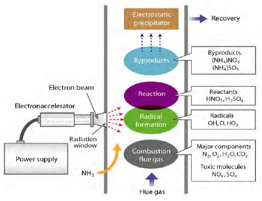
Electrons generated in a vacuum tube are accelerated by a high voltage into a gas-processing chamber through a small window. The electron-beam irradiation can dissociate and ionize the O2 and H2O in exhaust gas, forming oxidative radicals (e.g., O, OH, HO2) [24][25]. These oxidative species can turn NOx and SOx into HNO3 and H2SO4, respectively. Subsequently, ammonia (NH3) is added to the treated combustion flue to convert HNO3 and H2SO4 into ammonium nitrate (NH4NO3) and ammonium sulfate ((NH4)2SO4), respectively. These products can be repurposed to make fertilizer. The EBDS system shows potential applicability to simultaneously treat both NOx and SOx gases with a high efficiency [24]. However, this method has not yet been fully developed for practical use, owing to its high cost and large energy loss at the vacuum interface.
2.2 Dielectric barrier discharge (DBD)
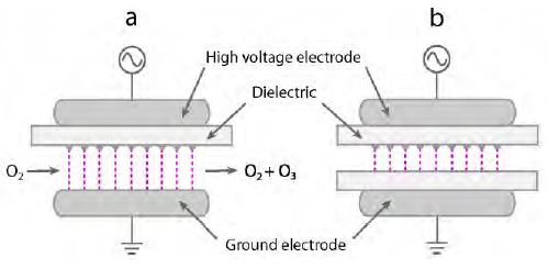
DBD is composed of a small pulsed micro discharge generated between electrodes covered with thin dielectric layers by a high alternating-current voltage (Figure 2) [26]. DBD is the most common technique for producing ozone. Ozone is applied for various cleaning processes such as sterilization [27], deodorization [28], and decolorization [29] owing to its strong oxidation. DBD with the ozone production is considered as an efficient technique for flue-gas cleaning and toxic-gas decomposition in diesel gas exhaust [30][31]. However, the efficiency of DBD for the removal of toxic gas is low at present, and the removal of NOx by DBD is currently under investigation in laboratory and pilot plants. The main obstacles hindering the application of DBD to large-scale processes are the need for an external cooling system, the high operation cost, and the incomplete removal of toxic gas. Therefore, the rational development and design of DBD systems are important tasks for improving the efficiency of DBD for practical use.
2.3 Electron beam–microwave (EB–MW) plasma hybrid system
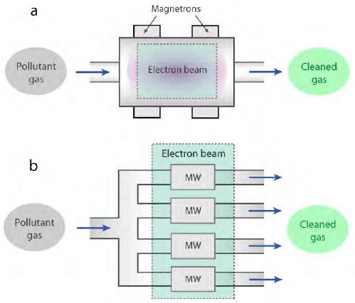
Figure 3 (a) shows a schematic of a single unit of an EB–MW plasma hybrid system [32]. It comprises multiple sets of magnetrons and a single EB. In this system, EB produces a high density of electrons with high energy to generate plasma. Additionally, MW irradiation helps to maintain the energy of generated electrons by re-energizing them. By combining EB and MW irradiation, the plasma energy can be maintained at a high level while the energy required for EB is reduced. In addition, contamination can be avoided owing to the absence of electrodes in the EB–MW hybrid system [32][33]. In a laboratory-scale experiment, the levels of NOx and SOx were reduced by up to 60% and 80%, respectively. This hybrid system can potentially be developed for handling larger gas volumes with a higher flow rate by constructing multiple parallel arrangements of a single hybrid system, as schematically shown in Figure 3 (b).
2.4 Plasma‒catalytic hybrid system
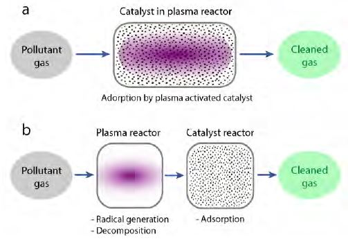
The combination of non-thermal plasma and the high reaction selectivity of catalysts can lead to an improvement in the removal efficiencies of toxic gases [34]-[36]. There are two types of this hybrid system. The first type is called in-plasma catalysis (IPC). Here, the catalysts are introduced into the plasma discharge (Figure 3 (a)), and toxic gas can be decomposed by the plasma. Simultaneously, the catalysts become activated under plasma exposure to react with the toxic gas for treatment. The second type is post-plasma catalysis (PPC). In the PPC system, the catalysts are placed in a zone separated from the plasma reactor. As shown in Figure 3 (b), the toxic gas is first decomposed by the plasma. Then, the residual contaminants that cannot be decomposed by the plasma, as well as byproducts, are transferred to the next reactor and removed by catalysts. The combination of plasma and catalysis in the treatment process can increase the reaction rate, extend the lifetime of the catalyst, and reduce the onset temperature of the catalytic reaction.
3. Conclusions
Non-thermal plasmas generated by different types of systems show great potential for the treatment of toxic gases emitted from marine diesel engines. Non-thermal plasma offers several advantages over conventional processes, such as operation at an ambient temperature, no need for external combustion devices, and the flexible treatment of various harmful gases. However, the practical use of non-thermal plasma in marine diesel engines has not been realized, owing to its high cost and low efficiency for large-scale processes. To realize its practical use, further intense development and design of non-thermal plasma systems are required. We believe that non-thermal plasma technology is a promising, efficient, ecological, and sustainable long-term solution for the abatement of NOx and SOx emitted from marine diesel engines in future smart ships.
Acknowledgments
The authors gratefully thank the financial support from Nagoya University for the joint research projects between Chulalongkorn University and Nagoya University via the research grant for the NU-PPC Plasma Chemical Technology Laboratory at Chulalongkorn University, Thailand.
This paper is extended and updated from the short version that appeared in the Proceedings of the International Symposium on Marine Engineering and Technology (ISMT 2016), held at Korea Maritime and Ocean University, Busan, Korea, November 3–4, 2016.
References
-
H. Abe, M. Yoneda, and N. Fujiwara, “Developments of plasma etching technology for fabricating semiconductor devices”, Japanese Journal of Applied Physics, vol. 47, p1435-1455, (2008).
[https://doi.org/10.1143/JJAP.47.1435]

-
A. V. Shah, H. Schade, M. Vanecek, J. Meier, E. Vallat-Sauvain, N. Wyrsch, U. Kroll, C. Droz, and J. Bailat, “Thin-film silicon solar technology”, Progress in Photovoltaic, vol. 12, p113-142, (2004).
[https://doi.org/10.1002/pip.533]

-
G. Sberveglieri, “Recent developments in semiconducting thin-film gas sensor”, Sensor and Actuator B: Chemical, vol. 23, p103-109, (1995).
[https://doi.org/10.1016/0925-4005(94)01278-P]

-
Th. Lampe, S. Eisenberg, and E. Rodri, “Plasma surface engineering in the automotive industry–Trends and future prospective”, Surface and Coating Technology, vol. 174-175, p1-7, (2003).
[https://doi.org/10.1016/S0257-8972(03)00473-0]

-
M. Laroussi, and X. Lu, “Room-temperature atmospheric pressure plasma plume for biomedical applications”, Applied Physics Letter, vol. 87, p113902, (2005).
[https://doi.org/10.1063/1.2045549]

- H. Höcker, “Plasma treatment of textile fiber”, Pure and Applied Chemistry, vol. 74, p423-427, (2009).
- V. Nehra, A. Kumar, and H. K. Dwivedi, “Atmospheric non-thermal plasma sources”, International Journal of Engineering, vol. 2, p53-58, (2008).
-
V. M. Donnelly, and A. Kornblit, “Plasma etching: Yesterday, today, and tomorrow”, Journal of Vacuum Science and Technology A, vol. 31, p050825, (2013).
[https://doi.org/10.1116/1.4819316]

-
K. N. Kim, S. M. Lee, A. Mishra, and G. Y. Yeom, “Atmospheric pressure plasmas for surface modification of flexible and printed electronic devices: A review”, Thin Solid Films, vol. 598, p315-334, (2016).
[https://doi.org/10.1016/j.tsf.2015.05.035]

-
X. Peng, A. Matthws, and S. Xue, “Plasma-based processes and thin film equipment for nano-scale device fabrication”, Journal of Materials Science, vol. 46, p1-37, (2011).
[https://doi.org/10.1007/s10853-010-4974-6]

-
K. Ostrikov, U. Cvelbar, and A. B. Murphy, “Plasma nanoscience: setting directions, tackling grand challenges”, Journal of Physics D: Applied Physics, vol. 44, p174001, (2011).
[https://doi.org/10.1088/0022-3727/44/17/174001]

- B. Sun, M. Sato, and J. S. Clements, “Use of a pulsed high-voltage discharge for removal of organic compounds in aqueous solution”, Journal of Physics D: Applied Physics, vol. 32(no. 15), p1908, (1999).
-
M. Tezuka, and M. Iwasaki, “Plasma induced degradation of chlorophenols in an aqueous solution”, Thin Solid Films, vol. 316(no.1-2), p123-127, (1998).
[https://doi.org/10.1016/S0040-6090(98)00401-5]

-
B. Jiang, J. Zheng, Q. Liu, and M. Wu, “Review on electrical discharge plasma technology for wastewater remediation”, Chemical Engineering Journal, vol. 236, p348-368, (2014).
[https://doi.org/10.1016/j.cej.2013.09.090]

-
H.-H. Kim, “Non-thermal plasma processing for airpollution control: A historical review, current issues, and future prospects”, Plasma Processes and Polymers, vol. 1, p91-110, (2004).
[https://doi.org/10.1002/ppap.200400028]

-
P. Talebizadeh, M. Babaie, R. Brown, H. Rahimzadeh, Z. Ristovski, and M. Arai, “The role of non-thermal plasma technique in NOx treatment: A review”, Renewable and Sustainable Energy Reviews, vol. 40, p886-901, (2014).
[https://doi.org/10.1016/j.rser.2014.07.194]

-
M. Bahri, F. Haghighat, S. Rohani, and H. Kazemian, “Impact of design parameters on the performance of nonthermal plasma air purification system”, Chemical Engineering Journal, vol. 302, p204-212, (2016).
[https://doi.org/10.1016/j.cej.2016.05.035]

- G. Panomsuwan, R. Rujiravanit, T. Ueno, and N. Saito, “Recent trends in plasma technology for marine engineering and applications”, Proceedings of the ISMT 2016, p66, (2016).
- V. Thanikachalam, “Energy demand and exhaust gas emissions of marine engines: Mitigating technologies and prediction”, International Journal of Advances in Engineering Research, vol. 9, p1-31, (2015).
- International Maritime Organization, “IB664E -MARPOL Annex VI & NTC 2008, 2013 Edition”, International Maritime Organization, London, UK, (2013).
- I. Komar, and B. Lalić, “Sea transport air pollution”, Current Air Quality Issues, F. Nejadkoorki (Eds), Croatia, Intech, (2015).
- F. D. Natale, C. CArotenuta, L. D’Addio, A. Lancia, T. Antes, M. Szudyga, A. Jaworek, D. Gregory, M. Jackson, P. Volpe, R. Beleca, N. Manivannan, M. Abbod, and W. Balachandran, “New technologies for marine diesel Engine emission control”, Chemical Engineering Transactions, vol. 32, p361-366, (2013).
-
M. Bai, B. Leng, and S. Mao, “Production of reactive oxygen species and application for NOx control”, Plasma Chemistry and Plasma Processing, vol. 34, p83-92, (2014).
[https://doi.org/10.1007/s11090-013-9493-1]

- T. Matsumoto, S. Yang, T. Namihira, and H. Akiyama, “Non-thermal plasma technic for air pollution control”, Air Pollution–A Comprehensive Perspective, B. Haryanto (Eds), Croatia, Intech, (2012).
-
A. G. Chmielewski, A. Ostapczuk, and J. Licki, “Electron beam technology for multi-pollutant emissions control from heavy fuel oil-fired boiler”, Journal of the Air & Waste Management Association, vol. 60, p932-938, (2010).
[https://doi.org/10.3155/1047-3289.60.8.932]

-
U. Kogelschatz, “Dielectric-barrier discharge: Their history, discharge physics, and industrial applications”, Plasma Chemistry and Plasma Processing, vol. 23, p1-46, (2003).
[https://doi.org/10.1023/A:1022470901385]

-
T. Iwamura, K. Nagano, T. Nogami, N. Matsuki, N. Kosaka, H. Shintani, and M. Katoh, “Confirmation of the sterilization effect using a high concentration of ozone gas for the bio-clean room”, Biocontrol Science, vol. 18, p9-20, (2013).
[https://doi.org/10.4265/bio.18.9]

-
T. M. Pan, K. Shimoda, Y. Cai, Y. Kiuchi, T. Akimoto, Y. Nagashima, M. Kai, M. Ohira, J. Segusa, T. Kuhara, and K. Maejima, “Deodorization of laboratory animal facilities by ozone”, Experimental Animals, vol. 44, p255-259, (1995).
[https://doi.org/10.1538/expanim.44.255]

-
K. Turhan, I. Durukan, S. A. Ozturkcan, and Z. Turgut, “Decolorization of textile basic dye in aqueous solution by ozone”, Dyes and Pigments, vol. 92, p871-901, (2012).
[https://doi.org/10.1016/j.dyepig.2011.07.012]

-
S. Müllen, and R.-J. Zahn, “Air pollution control by nonthermal plasma”, Contributions of Plasma Physics., vol. 47, p520-529, (2007).
[https://doi.org/10.1002/ctpp.200710067]

-
T. Kuwahara, K. Yoshida, K. Hanamoto, K. Sato, T. Kuroki, and M. Okubo, “Effects of exhaust gas temperature on oxidation of marine diesel emission particulates with non thermal-plasma-induced ozone”, Ozone: Science & Engineering, vol. 37, p518-526, (2015).
[https://doi.org/10.1080/01919512.2015.1060881]

-
N. Manivannan, W. Balachchandran, R. Belelca, and M. Abbod, “Non-thermal plasma technology for abatement of NOx and SOx from the exhaust of marine diesel engine”, Journal of Clean Energy Technologies, vol. 2, p233-236, (2014).
[https://doi.org/10.7763/JOCET.2014.V2.130]

-
N. Manivannan, W. Balachandran, R. Beleca, and M. Abbod, “Microwave plasma system design and modeling for marine exhaust gas abatement of NOx and SOx”, International Journal of Environmental Science and Development, vol. 6, p151-154, (2015).
[https://doi.org/10.7763/IJESD.2015.V6.579]

-
V. Demidiouk, J. O. Chae, “Decomposition of volatile organic compounds in plasma-catalytic system”, IEEE Transactions on Plasma Science, vol. 33, p157-161, (2005).
[https://doi.org/10.1109/TPS.2004.841621]

-
J. V. Durme, J. Dewulf, C. Leys, H. V. Langenhove, “Combining non-thermal plasma with heterogeneous catalysis in waste gas treatment”, Applied Catalysis B: Environmental, vol. 78, p324-333, (2008).
[https://doi.org/10.1016/j.apcatb.2007.09.035]

-
A. Mizuno, “Generation of non-thermal plasma combined with catalysts and their application in environmental technology”, Catalysis Today, vol. 211, p2-8, (2013).
[https://doi.org/10.1016/j.cattod.2013.03.029]


