Motion characteristics along the shape of the activating body of a floating wave energy convertor
Copyright © The Korean Society of Marine Engineering
This is an Open Access article distributed under the terms of the Creative Commons Attribution Non-Commercial License (http://creativecommons.org/licenses/by-nc/3.0), which permits unrestricted non-commercial use, distribution, and reproduction in any medium, provided the original work is properly cited.
Abstract
Wave energy generation systems can be divided into oscillating water chamber type, over topping device type and wave activating body type. The wave activating body type converts wave energy to kinetic energy, and the power generation amount increases as the motion of an activating body increases. In this paper, the wave energy convertor consists of a main body, which has an H-shape, and the activating body. These are connected by a bar-type bridge. By the incident wave, when the activating body moves with vertical motion this motion is consequently converted into rotational motion. The twisting moment and angular velocity at a shaft of convertor are calculated according to various conditions of the incident wave and the shape of the activating body. This can be used as a basic idea for determining the design of wave activating body type convertor.
Keywords:
Renewable energy, Floating wave energy convertor, Wave activating body, Regular wave, Irregular wave, Study of motion characteristics1. Introduction
Due to the recent problems of the depletion of fossil fuel and environmental pollution, the need for alternative energy sources has been emphasized, with natural energy sources such as wind power, solar power, tidal power, wave power, and hydraulic power being studied and developed as alternatives. Among them, ocean energy such as tidal and wave energy is more regular, predictable, and stable than wind and solar energy. In addition, the energy density of water is 800 times higher than of air. Therefore, it is important to develop the devices extracting valuable energy from ocean sources [1]. Wave power generators can be classified into three types accord- ing to the mechanism of the energy conversion system: Oscillating Water Chamber (OWC) type, in which electric power is generated by the air flow in water chambers caused by the movement of sea levels, Over Topping Device (OTD) type in which inclined planes are set in the moving direction of waves and the seawater topping over structures is stored in order to generate electric power using the kinetic energy of falling seawater between average sea level and heads, and the Wave Activating Body (WAB) type in which electric power is produced by the kinetic energy generated by the vertical and rotational movement of the activating structure induced by waves. Among these converter types, the WAB type has the advantage of having good efficiency because the kinetic and potential energy of waves are directly converted into mechanical energy [2]. Many of the WAB type are suggested and researched according to the activating system: pendulum wave energy converter in which electric power is produced by converting movement of hinged pendulum structure; bottom-hinged flap wave energy converter in which the system uses the performance of bottom- hinged flap [3]. As relative movement between the activating body and the main body is important, the sizing of elements should be determined so that the efficiency of power generation may be improved [4]. The goal of the study was to analyze the kinetic properties of the activating body of floating WAB type wave power generators, and for this analysis, movement simulation of wave power generators was performed using a commercial program, AQWA, for each case. The translation motion and rotation motion of the main body were controlled by using mooring systems, and in the case of the activating body, relative motions of sway, roll, and yaw of the main body were controlled using the connection between the main body and hinges. The incident wave coming from the front of structures was deemed as an external force, and the quantity of generated power was compared depending on the shape change of the moving body.
2. Floating WAB type wave-power generator
2.1 Basic shape
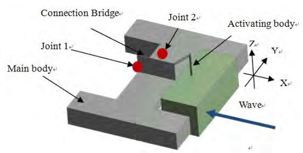
The WAB type wave-power generator was modeled for this paper as shown in Figure 1. The wave-power generator consists of two main bodies, two connection bridges, and an activating body. The relative motions of heave and pitch between the activating body and main body generated by incident waves are changed to rotation energy through Joint 2, and the energy is transmitted to Joint 1 of main body, and electric power is produced by this rotation energy. The basic shape and specification of the simulated WAB type wave-power generator are shown in Figure 1 and Table 1, respectively. Here, L, B, D, and d mean the length, width, depth, and draft of the structure, respectively.
2.2 Floating body
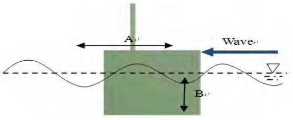
The shape change of the activating body was simulated for nine cases, depending on A indicating the length of an activating body and B indicating its depth, as shown in Figure 2 and Table 2, and the width of the main body and activating body of the wave-power generator were maintained at constant levels. The activating body was designed to have a low center of gravity at 40% range of depth of the structure by installing a mass in order to avoid excessive pitch and guarantee dynamic stability.
2.3 Mooring system
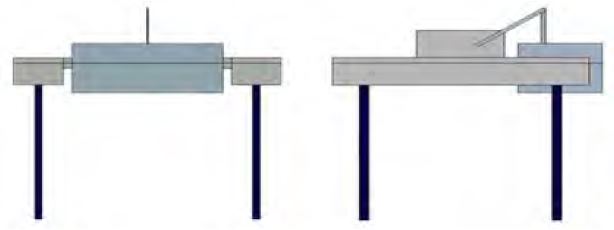
The mooring systems of floating wave-power generators are available in various types: catenary mooring, multi-catenary mooring, turret mooring, SALM (Single Anchor Leg Mooring), and fixed tower mooring [5]. Tendon mooring type was used in this paper, as shown in Figure 3, and the lower part of the main body was vertically connected with the sea bottom so that the pretension force is applied acting at the mooring line.
The stiffness of the mooring line was assumed to have a linear spring constant, and the acting force was calculated. The restoring coefficient can be obtained from the mass and natural period of the system using Equation (1).
| (1) |
Where, kt is the restoring coefficient of the floating structure system including the mooring line, mt is the mass that includes the mass and added mass of the system, and T is the natural period of the whole structure including the mooring system.
kt is divided into ks which is the restoring coefficient that does not include the mooring stiffness and km which is the stiffness of the spring of the mooring line.
| (2) |
The restoring coefficient of the structure, ks, is obtained from the water plane area of the floating body of the structure, Aw, density p, and acceleration of gravity, g, using Equation (3).
| (3) |
The constant stiffness of spring, km, may be obtained using Equations (2) and (3), and the pretension force from the displacement load and body mass to the mooring line and the expanded length of each mooring line, X, can be obtained. Here, ▽ is displacement load.
| (4) |
3. Motion analysis of a wave-power generator in waves
3.1 Condition of incident wave
The incident waves were applied as regular and irregular waves, and regular waves were designed as shown in Table 3. The period of incident waves was selected by referring to the average period for 2 years in target sea (Chilbaldo Island) [6].
Irregular waves were designed with JONSWAP spectrum to both types of waves as shown in Table 4. As the obtained wind velocity on the sea was taken 3.6m above sea level, the velocity was corrected to 10m-height velocity using Equation (5) and was applied to JONSWAP spectrum.
| (5) |
Where, Uh,Uh1,h1,h,α are the velocity at corrected height, average velocity at measurement height, measurement height, corrected height and velocity distribution index, respectively. Measurement height was 3.6m and corrected height was 10m. Velocity distribution index was deemed to be 0.1 because 0.1 is used in the case of sea and desert [7]. However, wind was used for configuration of the JONSWAP spectrum, and the influence of external wind was neglected in order to identity the motion property of floating bodies by wave force.
3.2 Calculation power amount
In order to compare and analyze the simulation result, the motion of the wave-power system generated by incident waves is expressed as power amount using Equation (6)[3].
| (6) |
The amount is obtained by multiplying the moment, b, generated in Joint 1 when WAB type motion is converted into rotation energy through a connection bridge by angular speed, θ. In Equation (6), t is time and T is the whole time of simulation.
4. Result of motion analysis of a wave-power generator in waves
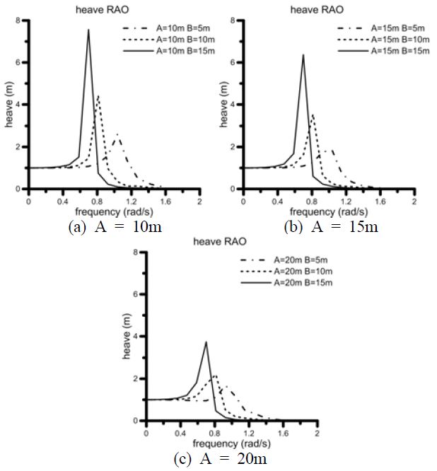
As the heave motion of the activating body is an important factor in floating power generation, RAOs (Response Amplitude Operator) in heave direction depending on shape are shown in Figure 4. The resonance area moved to low frequency when the depth of floating body, B, increased. In contrast, the change in the length of floating body, A, did not influence the resonance area, but when A was increased, response motion was reduced. The reason is that when floating body is put on the wave top, it ascends, and when it is put on the wave hollow, it descends; when the length of floating body was increased, the acting forces at wave top and wave hollow neutralized each other.
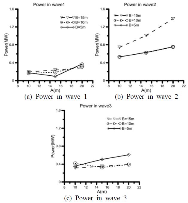
The power amount of simulated regular waves is shown in Figure 5. The x-axis is the change in A and the y-axis is the power amount. Diamond symbols mean the cases in which B is 5m, circle symbols mean the cases in which B is 10m, and inverted triangle symbols mean the cases in which B is 15m.
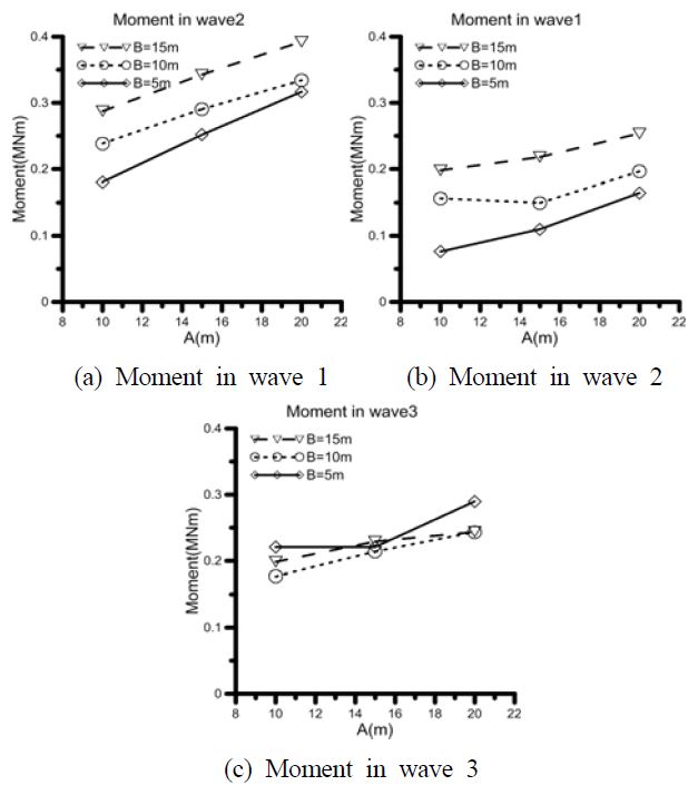
Change in B did not show any apparent trend, but when A was increased, the power amount was increased. When this result complied with the RAOs in heave direction of floating body in Figure 4, it was contrary to the case in which, when A was increased, the response in heave direction was reduced. Therefore, the moment generated in the generation axis was shown in Figure 6 in order to analyze the cause.
The moment can be calculated from the directional force and the length of moment arm, and as moment arm is constant in every case, the moment force generated on the generation axis can be determined by the directional force to move the moment arm. Also, as the directional force consists of the mass and acceleration of the floating body and the mass is significantly larger than the acceleration, the moment force can be deemed to be controlled by the mass of the floating body.
Based on this phenomenon, it can be explained that the power amount is increased when A is increased, although the heave response is reduced.
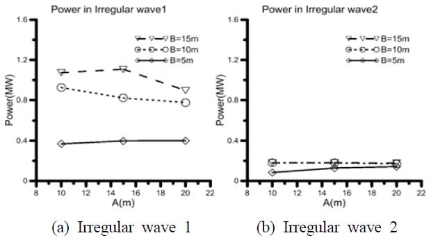
The power amount of simulated irregular waves is shown in Figure 7. Although the power quantity produced is different due to the difference in significant wave height of incident waves, the trends of the two graphs are similar. In both graphs, when B was relatively small, the power amount was increased as A increased, and in contrast, when B was large, the power amount was reduced when A was increased.
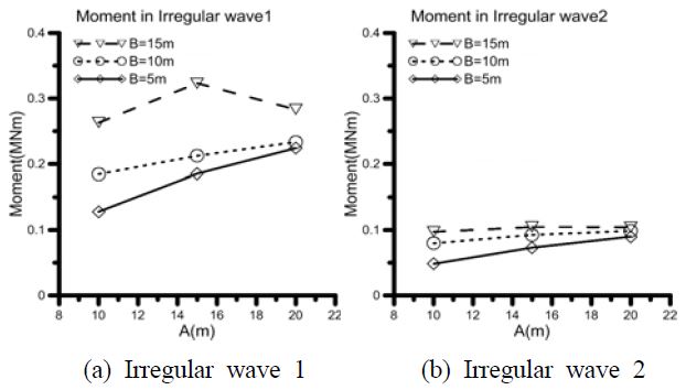
The produced moment on generation axis, joint 1 in Figure 1, is shown in Figure 8 in order to analyze the trends of power generation. As the moment is deemed to be controlled by the mass of the activating body, as explained in the result of simulated regular waves, the moment increases when A and B increase.
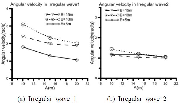
The angular speed generated on the generation axis is shown in Figure 9. When reviewing the angular speed, the moment force shows different result; an increase in B did not show any apparent trend, but when A was increased, angular speed was reduced. As explained above, this is the result in which when A was increased, the forces acting on the floating body neutralized each other.
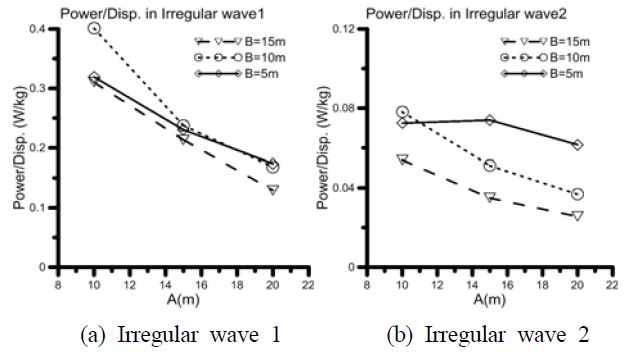
When moment graphs and angular speed graphs are integrated, the reason why the power amount is reduced when A is increased is that the motion of the floating body is reduced. However, in cases where B is 5m, the power amount was increased when A was increased, and the reason was that the moment increment when A was increased was relatively large. As mentioned above, as the moment is largely influenced by the mass, in order to identify whether an increased power amount is the result of changed shape or changed mass, power amount was divided by displacement load, and the results are shown in Figure 10. In the result, the x-axis shows the change in A and the y-axis shows the power amount for unit displacement load.
The power amount for unit displacement load can be deemed to be reduced when B is increased, although this result is not consistent in all cases. Also, when A was increased, the power amount for unit displacement load was reduced. In addition, of 9 cases, the pair cases which had the same displacement load but different shapes are expressed as solid line circles and dotted line circles. Reviewing the result, power amount was reduced with increased A.The power amount for unit displacement load can be deemed to be reduced when B is increased, although this result is not consistent in all cases. Also, when A was increased, the power amount for unit displacement load was reduced. In addition, of 9 cases, the pair cases which had the same displacement load but different shapes are expressed as solid line circles and dotted line circles. Reviewing the result, power amount was reduced with increased A.
5. Conclusion
The object of this study is to determine the activating body shapes of a floating wave energy convertor that are more useful and efficient by comparing the power amount of various shapes of the activating body. Therefore, energy efficiency, which is converted from wave energy to electronic energy, is not considered but the power amount is merely considered to contrast all cases. In this study, 6-degrees of freedom simulation was performed after modeling floating WAB wave-power generators using a commercial software package, AQWA. In order to identify the motion property depending on shape change, power amount was calculated and analyzed based on the obtained moment force and angular speed, and it was found that the power amount of a WAB wave-power converter is controlled by the mass of activating body, and that, if the body has a constant displacement load, a short and deep shape is advantageous.
Acknowledgments
This work was the result of a study conducted for the BK21 Plus Project and Special Technology Commercialization Project. This work was supported by Development Fund Foundation, Gyeongsang National University, 2015.
References
-
S. B. Lee, K. Hadano, and B.Y. Moon, “A study for electric power of float-counterweight wave energy converter”, Journal of the Korean Society of Marine Engineering, 38(7), p936-942, (2014), (in Korean).
[https://doi.org/10.5916/jkosme.2014.38.7.936]

- R. W. Yeung, A. Peiffer, N. Tom, and Tomasz Matlak, “Design, analysis, and evaluation of the UC-Berkeley wave-energy extractor”, Journal of Offshore Mechanics and Arctic Engineering, 134(2), Ocean Renewable Energy, p021902-021908, (2011).
- S. S. Kim, J. H. Lee, and D. H. Kang, “A study of motion characteristics along the shape of floating body of the wave energy convertor,”, Proceedings of Korean Association of Ocean Science and Technology Societies, p1854-1857, (2014).
- B. W. Nam, S. Y. Hong, K. B. Kim, J. Y. Park, S. H. Shin, “A numerical analysis on wave-induced motion characteristics of floating pendulor wave energy converter,”, Proceedings of Korean Association of Ocean Science and Technology Societies, p1455-1459, (2011).
-
L. Johanning, J. Wolfram, and G. H. Smith, “Mooring design approach for wave energy converter”, Proceedings of the Institution of Mechanical Engineers, Journal of Engineering for the Maritime Environment, 220(4), p159-174, (2006).
[https://doi.org/10.1243/14750902JEME54]

- KMA, Report of Marine Data, Retrieved from Korea Meteorological Administration, (Updated September 2013), http://www.kma.go.kr/repositary/sfc/pdf/marine_mon_201308.pdf Accessed August 11, 2014.
- D. H. Ghang, S. C. Shin, S. K. Na, and S. Y. Kim, “A study on the design of a floating sea wind-power generator in consideration of motion characteristics,”, Proceedings of Korean Association of Ocean Science and Technology Societies, p870-875, (2012).

