Runner Design and Internal Flow Characteristics Analysis for an Ns=200 Francis Hydro Turbine Model
Copyright © The Korean Society of Marine Engineering
This is an Open Access article distributed under the terms of the Creative Commons Attribution Non-Commercial License (http://creativecommons.org/licenses/by-nc/3.0), which permits unrestricted non-commercial use, distribution, and reproduction in any medium, provided the original work is properly cited.
Abstract
Francis hydro turbines have been most widely used throughout the world because of their wide range of head and flow rate applications. In most applications, they are used for high heads and flow rates. Currently, Korea is developing technology for Francis hydro turbine design and manufacture. In order to understand the internal details of Francis hydro turbines further, a new Francis turbine model runner is designed and model internal flow characteristics are investigated. The specific speed of the Francis hydro turbine model runner is Ns = 200 m-kW-min-1. The runner blade is designed successfully according to the port area and one-dimensional loss analysis. The best efficiency point of the Francis hydro turbine model achieves 90% at the design condition. CFD analysis yields a hill chart of the Francis hydro turbine model for use in predicting performance.
Keywords:
Francis hydro turbine, Internal flow, Performance, Runner design1. Introduction
Hydropower has been a mainstream renewable energy technology for decades, and currently represents approximately 16 % of global electricity generation. However, while hydropower has been a steady constant in the energy supply scene, the energy mix as a whole is undergoing rapid and dramatic change [1]. Moreover, Francis hydro turbines have been the most widely used worldwide because of their wide range of head and flow rate applications. They also provide good efficiency, approaching the 90% region.
Research on hydraulic turbine technology is continuously proceeding with the development of hydroelectricity. Chen et al. [2] studied the effect of runner blade loading on the performance and internal flow of a Francis hydro turbine model. There are three different blade loadings conducted to compare internal flow characteristics and performance. Their conclusion was that front loading achieves the best efficiency in comparison with other loadings.
Chen et al. [3] conducted a numerical analysis on the effect of the port area of blades on the performance of a Francis hydro turbine. The effect of the port area of runner blades on the outflow angle from runner passages on performance is quite significant. A correct port area reduces the energy loss at the draft tube and increases turbine efficiency.
Chen et al. [4] designed the blades of a Francis turbine on the basis of port area and loss analysis successfully. The best efficiency of 92.6% was achieved using this method.
Moreover, there are some new applications of the Francis hydro turbine runner in city water supply systems designed to recycle energy. Chen et al. [5][6] examined feasibility and performance studies on the flow passage shape for an inline Francis hydro turbine. The inline casing is used instead of the traditional spiral casing, which has a more compact-size and is very convenient for manufacturing.
Research on hydraulic turbine technology is continuously proceeding with the development of hydroelectricity. In this study, a new Francis hydro turbine was designed for a specific speed (Ns) of 200 m-kW-min-1 as calculated by the following equation. Internal flow characteristics are investigated. The hill chart of this Francis hydro turbine was produced by computational fluid dynamics (CFD) analysis to predict the performance in detail.
| (1) |
where N is the rotational speed, P is the power, H is the head of turbine.
2. Francis hydro turbine Model and Numerical Method
2.1 Turbine runner model
This study is a continuation from a previous study [7]. In the previous study, a CFD analysis was conducted to investigate the internal flow characteristics of the Francis hydro turbine model with various internal flow passage shapes. However, the efficiency of the runner was still relatively low. Therefore, a similar design method was applied as in the previous study [4] to design the new Francis hydro turbine runner for Ns = 200 m-kW-min-1.
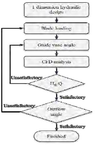
The flow chart of the Francis hydro turbine design is shown in Figure 1. There are two redesign processes in this design flow chart. The turbine head is controlled by the guide vane opening at the design point condition. The outflow angle from the runner outlet is controlled by the blade loading and blade outlet angle. The guide vane angle and blade loading were modified until the turbine head and outflow angle from the runner were satisfactory.
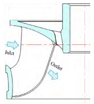
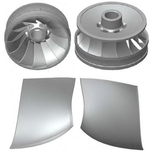
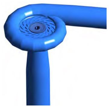
The meridional shape of the Francis hydro turbine model is shown in Figure 2. The runner inlet diameter is D1 = 377.5 mm, and the outlet diameter is De = 350 mm. The numbers of stay vanes and guide vanes are Zs = Zg = 16, and the number of runner blade vanes is Zr = 13. The effective head of the Francis hydro turbine model is H = 18 m at the design condition, and the flow rate is Q = 0.45 m3/s. The rotational speed of the runner is N = 900 min-1. The specific speed at the design point is Ns = 200 m-kW-min-1. Table 1 shows the specifications of the Francis hydro turbine model runner. Figure 3 shows the three-dimensional model of the new Francis hydro turbine model runner and blade shape. Figure 4 shows the full fluid domain of the turbine model for CFD calculations, including the casing, stay vane, guide vane, runner, draft tube, and clearance gap.
2.2 Numerical methods
The performance investigation and internal flow analysis of the turbine model was conducted by CFD analysis. The CFD analysis is a very useful tool for predicting hydraulic machinery performance at various operating conditions [2]-[11]. A turbulence model dependence test was conducted in the previous study [7] and a shear stress transport (SST) model has been applied in this analysis, which is well known to estimate both separation and vorticity occurring on the walls of complicated blade shapes. This study employs the commercial CFD code ANSYS CFX [12] to conduct CFD analysis. The operating condition maintains the head at 18 m and the flow rate range varies according to the guide vane openings. The boundary conditions are summarized in Table 2.
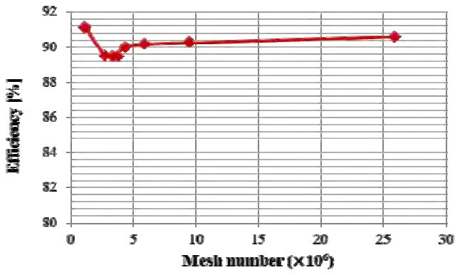
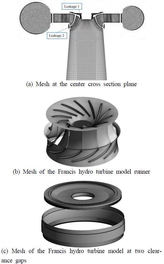
Moreover, according to the mesh dependence test as shown in Figure 5, a mesh number of approximately 11.0 × 10⁶ applied for all the cases, and y+ was approximately 59 for the runner blade surface. Figure 6 shows the fine numerical mesh used for Francis hydro turbine model components. The extended inlet pipe, stay vane, guide vane, and draft tube of the turbine model are modeled with a hexahedral numerical mesh. The casing part of the turbine model fluid domain is modeled with a tetrahedral mesh.
3. Results and Discussion
3.1 Performance characteristic curves
For performance analysis of the Francis turbine model, all the flow rates and rotation speeds were normalized to unit flow and unit speed, respectively. Unit normalization was calculated through the following equations:
| (2) |
| (3) |
| (4) |
where N11 is the unit speed, Q11 is the unit flow, N is the rotational speed, D1 is the diameter of the runner, Q is the flow rate, H is the head of the turbine, T is the torque, and ω is the rotational speed of the runner.
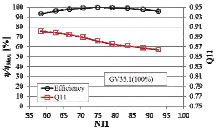
Performance curves with the characteristics of efficiency and unit flow with respect to unit speed at the design guide vane (GV) opening for the Francis hydro turbine model are presented in Figure 7. From the results, it can be inferred that this turbine model performs quite well. Moreover, there is a wide unit speed range with high efficiency, which means that there is a wide operation range with good performance. The head was maintained at 18 m, which is the design head of the Francis hydro turbine model. This efficiency takes into account the leakage loss, as well.
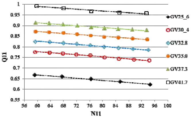
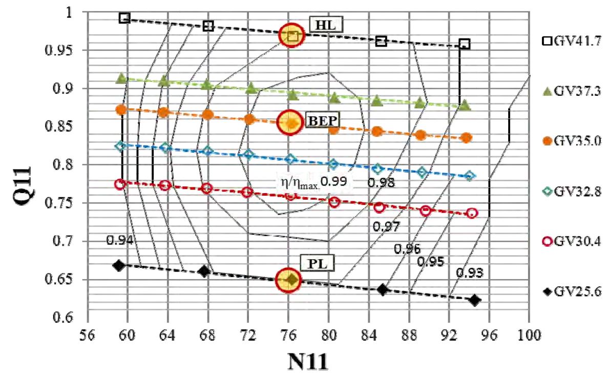
Figure 8 shows the relationship between unit flow (Q11) and unit speed (N11). It can be seen that there was an almost linear distribution between the unit flow and unit speed. The unit flow of the turbine was higher for the high guide vane opening in comparison to the low guide vane opening. The hill chart of the Francis hydro turbine model obtained by CFD analysis is shown in Figure 9. The efficiency in the hill chart was normalized by η/ηmax. It can be seen that a high efficiency ratio of 0.99 was present at the guide vane opening from 30.4 mm to 37.3 mm. Therefore, the operation range with high performance for this turbine is relatively wide.
3.2 Loss distribution
The losses in the clearance gap part mainly consisted of a degraded volumetric leakage flow rate. In order to study the Francis hydro turbine volumetric loss distribution in detail, the part load (PL), best efficiency point (BEP), and high load (HL) cases were typically selected for investigating the internal flow characteristics as shown in Figure 9.
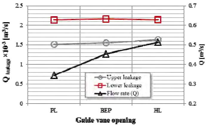
Figure 10 shows the results of the volumetric leakage flow rate distribution in the clearance gap part. The volumetric leakage flow rates at all the operating points were relatively small. The volumetric leakage flow rate Qleakage in the lower part was higher than that in the upper part. The main flow rate increased from partial load to high load while the volumetric leakage flow rate remained almost constant. As the head of the turbine was maintained, it can be conjectured that the volumetric leakage flow rate mainly depends on the pressure difference between the turbine inlet and outlet.
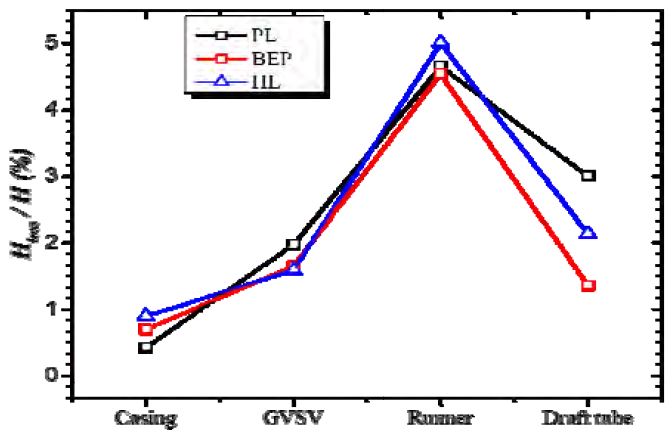
Figure 11 shows the loss distribution for each component. It can be seen that the BEP condition experienced its minimum loss in the runner and draft tube passage. Swirling flow occurs in the draft tube at off-design points, which contributes to losses in the turbine. There are only friction losses in the casing passage. Therefore, the HL condition at high velocity contributes to a large loss in the casing passage.
3.3 Streamline distribution on the blade
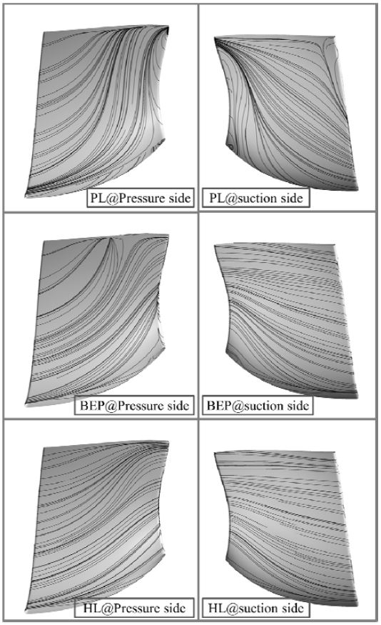
Streamline distributions on runner blade surfaces clearly revealed the internal flow characteristics at the blade passages. In this study, the streamline on the blade surface at PL, BEP and HL was selected for further investigation.
The streamlines on the blade surface showed that there are better streamline distributions at both pressure and suction sides at the high-load operating condition than at others. Because of centrifugal force, secondary flow occurs to a large extent at both pressure and suction sides near the leading edge at the partial load condition where the loss occurs to a large extent, thereby reducing performance. The HL velocity was larger than that for the BEP. Therefore, the effect of centrifugal force on the secondary flow was weak for the HL condition, and the streamlines on the HL runner surfaces were relatively better than those for BEP. In general, the minimum loss in the runner and draft tube passage was located at the BEP condition.
4. Conclusion
The study investigated the performance of a Francis hydro turbine model with a newly designed runner at a specific speed of 200 m-kw-min-1. The hill chart performance of this turbine model was obtained by conducting CFD analysis. This Francis hydro turbine model performed quite well, achieving maximum efficiency in the condition of maintaining head at 18 m. Moreover, it exhibited a wide unit speed range with high efficiency, which means that there is a wide operation range with good performance. Three typical loads were selected for the study: partial load, the best efficiency point, and high load. The volumetric leakage mainly depends on the pressure difference between the turbine inlet and outlet. As the head was maintained, the volumetric leakage flow rates in the upper and lower parts remained constant in this study. The streamline distribution on the blade surface at partial load was much better than that at high load for this Francis hydro turbine model runner.
Acknowledgments
This work was supported by the New and Renewable Energy of the Korea Institute of Energy Technology Evaluation and Planning (KETEP) grant funded by the Korea government Ministry of Trade, Industry and Energy (No. 2013T100200079).
References
- IHA Central Office, 2015 Hydropower Status Report, International Hydropower Association, https://www.hydropower.org/ Accessed May 05, 2016.
-
Z. Chen, P. M. Singh, and Y. D. Choi, “The effect of runner blade loading on the performance and internal flow of a francis hydro turbine model”, Journal of Mechanical Science and Technology, 30(4), p1617-1623, (2016).
[https://doi.org/10.1007/s12206-016-0317-0]

-
Z. Chen, and Y. D. Choi, study on the effect of port area of blade on the performance of francis hydro turbine”, The KSFM Journal of Fluid Machinery, 19(1), p05-10, (2016).
[https://doi.org/10.5293/kfma.2016.19.1.005]

-
Z. Chen, P. M. Singh, and Y. D. Choi, “Francis turbine blade design on the basis of port area and loss analysis”, Energies, 9(3), (2016).
[https://doi.org/10.3390/en9030164]

-
C. Chen, P. M. Singh, M. Inagaki, Y. D. Choi, “A feasibility study on the flow passage shape for an inline francis hydro turbine”, The KSFM Journal of Fluid Machinery, 18(2), p5-13, (2015).
[https://doi.org/10.5293/kfma.2015.18.2.005]

-
C. Chen, M. Inagaki, and Y. D. Choi, “A study on the performance and internal flow of inline Francis turbine”, Journal of the Korean Society of Marine Engineering, 38(10), p1225-1231, (2014).
[https://doi.org/10.5916/jkosme.2014.38.10.1225]

-
Z. Chen, Q. Wei, P. M. Singh, and Y. D. Choi, “Internal flow characteristics of a francis hydro turbine model by internal flow passage shapes, The KSFM Journal of Fluid Machinery, 18(5), p19-25, (2015).
[https://doi.org/10.5293/kfma.2015.18.5.019]

- M. K. Shukla, R. Jain, V. Prasad, and S. N. Shukla, “CFD analysis of 3-D flow for francis turbine”, MIT International Journal of Mechanical Engineering, 1(2), p93-100, (2011).
-
H. J. Choi, M. A. Zullah, H. W. Roh, P. S. Ha, S. Y. Oh, and Y. H. Lee, “CFD validation of performance improvement of a 500 kw francis turbine”, Journal of Renewable Energy, 54, p111-123, (2013).
[https://doi.org/10.1016/j.renene.2012.08.049]

-
J. C. Wu, K. Shimmei, K. Tani, K. Niikura, and J. Sato, “CFD-based design optimization for hydro turbines”, Journal of Fluids Energy, 129(2), p159-168, (2006).
[https://doi.org/10.1115/1.2409363]

- R. Khare, V. Prasad, and S. Kumar, “CFD approach for flow characteristics of hydraulic francis turbine”, International Journal of Engineering Science and Technology, 2(8), p3824-3831, (2010).
- ANSYS Inc, “ANSYS CFX Documentation”, Ver. 15.

