수신기의 기울기 및 방위를 고려한 가시광 통신기반 3차원 실내 위치인식에 대한 연구
Copyright © The Korean Society of Marine Engineering
This is an Open Access article distributed under the terms of the Creative Commons Attribution Non-Commercial License (http://creativecommons.org/licenses/by-nc/3.0), which permits unrestricted non-commercial use, distribution, and reproduction in any medium, provided the original work is properly cited.
초록
수신된 신호세기강도(RSSI)를 이용한 가시광통신기반 실내위치인식은 다른 무선 통신 위치인식 기법에 비해 정확성이 높기 때문에 많이 연구되고 있다. 하지만 수신기의 기울기와 방위에 따라 RSSI가 변할 수 있기 때문에 동일한 위치에서 수신된 신호조차도 큰 오차가 발생할 수 있다. 따라서 본 논문에서는 수신기의 기울기 변화에 의해 발생하는 오차를 감소시키기 위해 가우스-뉴턴(Gauss-Newton) 기법을 적용한 가시광통신기반 3차원 실내위치인식 알고리즘을 제안한다. 제안한 시스템은 수신된 RSSI를 선형 최소자승기법(LSM)을 적용하여 수신기의 초기 위치를 선정함으로써 연산량을 줄이고 수신기의 방위각과 기울기의 변화에 의하여 획득된 RSSI를 포함하는 3차원 비선형 모델에 가우스-뉴턴 기법을 사용하여 정확도를 개선하였다. 제안한 알고리즘의 타당성을 검증하기 위하여 16개의 LED 조명이 설치된 6×6×3m3의 실내 공간에서 수신기의 기울기 및 방위각 변화에 따른 기존의 선형 LSM 기반 삼변측량기법과 제안한 방법에 대한 오차를 비교 및 분석하였다. 실험결과 제안한 알고리즘 위치 정확도가 기존의 선형 LSM 기반 삼변측량기법 대비 82.5% 개선되었다.
Abstract
Indoor localization based on visible-light communication using the received signal strength intensity (RSSI) has been widely studied because of its high accuracy compared with other wireless localization methods. However, because the RSSI can vary according to the inclination and azimuth of the receiver, a large error can occur, even at the same position. In this paper, we propose a visible-light communication-based 3-D indoor positioning algorithm using the Gauss–Newton technique in order to reduce the errors caused by the change in the inclination of the receiver. The proposed system reduces the amount of computa-tions by selecting the initial position of the receiver through the linear least-squares method (LSM), which is applied to the RSSIs, and improves the position accuracy by applying the Gauss–Newton technique to the 3-D nonlinear model that contains the RSSIs acquired by the changes in the azimuth and inclination of the receiver. In order to verify the validity of the pro-posed algorithm in an indoor space with dimensions of 6 m × 6 m × 3 m where 16 LED lights are installed, we compare and analyze the errors of the conventional linear LSM-based trilateration technique and the proposed algorithm according to the changes in the inclination and azimuth of the receiver. The experimental results show that the location accuracy of the pro-posed algorithm is improved by 82.5% compared to the conventional LSM-based trilateration technique.
Keywords:
Received signal strength intensity, Vible-light communication, Indoor localization, Gauss-Newton technique키워드:
신호세기강도, 가시광통신, 실내위치인식, 가우스-뉴턴 기법1. 서 론
최근 실생활에 ICT(Information and Communication Tech- nology)가 보편화됨에 따라 실외공간에서 제공되던 다양한 서비스들이 점차 실내공간까지 확장되고 있다. 이러한 육상 및 해상의 실내 공간에서 여러 서비스들을 제공하기 위해서는 기본적으로 사용자들의 위치를 파악하는 기술이 필수적이다[1]-[7]. 서비스 중인 실외 측위 방법으로는 위성기반 항법 장치인 GPS(Global Positioning System) 또는 이동통신 기지국 기반의 Cell ID 방식 등이 주로 사용되고 있다. 하지만 이러한 방식들은 전파의 낮은 투과율과 정확성 등으로 인해 사용자들이 만족할 만한 실내 측위 서비스를 제공하기 어렵다.
따라서 다양한 통신방식이 적용된 실내 위치측위기법들이 활발히 연구되고 있다[8]. 현재 실내측위에 사용되는 기술은 RFID[9], UWB(Ultra-wide band)[10], Wi-Fi[11] 등 많은 근거리 무선 통신 방법이 적용되고 있다[12]-[20]. 이러한 근거리 무선 통신 기술기반의 측위 방법은 벽이나 외부의 물체로 인한 신호의 차단이 어렵고, 다른 전자파들의 간섭으로 인한 오차 및 주파수 용량의 한계 등의 문제점이 있다. 이를 보완하기 위하여 발광다이오드(LED) 조명을 이용한 가시광통신기술을 응용한 실내 위치 측위 기법이 연구되고 있다[21]-[26].
가시광통신은 가시광선(380~700nm)을 이용해 LED의 가시광선을 눈에 보이지 않는 속도로 점멸시켜 정보를 전달하는 기술이다. 가시광통신은 넓은 가시광선 대역을 사용하기 때문에 큰 주파수 용량을 가지고 있으며, 다른 무선 통신기반의 위치 측위 기술에 비해 실내 공간의 벽이나 외부 물체로 인한 신호의 차단이 가능하여 방과 방의 사이, 층간 구분이 명확하여 높은 정확도를 가진다. 가시광통신기반 실내 위치측위 기법은 AoA (Angle of Arrival)[27], ToA (Time of Arrival)[28], TDoA (Time Difference of Arrival)[29], RSSI[30] 등의 다양하다. AoA는 LED 광원의 직진성을 이용하기 때문에 각도 따라 추가적인 조명의 설치가 요구되며, 신호의 송수신 시간을 측정하는 ToA, TDoA는 동기화가 필요하기 때문에 엔코더와 같은 통신 장치의 높은 성능이 요구된다. RSSI는 송신기에서의 수신된 신호세기를 이용하는 기법으로 대부분 송신기와 수신기의 위치가 평행일 경우 매우 높은 정확도를 가진다. 그러나 실제 송수신기의 수평 상태를 유지하기 어렵기 때문에 위치의 오차는 크게 발생한다.
Yamaguchi et al.[31]은 OOC(Optical Orthogonal Codes)를 이용한 가시광통신 실내위치인식을 제안했다. 다른 신호들을 구분하기 위해 OOC를 사용하였고 선형 LSM 삼변측량기법이용하여 수학적인 모델링과 시뮬레이션을 통해 높은 정확도를 보인다. Kim et al.[32]은 가상 가시광 중첩을 이용한 RSSI 기반의 실내 측위법을 제안했다. 그러나 위 두 개의 연구는 실질적으로 단말기를 소지한 사용자의 위치를 추정 할 경우, 송신기와 수신기는 평행상태를 유지하기 어렵기 때문에 송신기와 수신기 사이의 거리뿐만 아니라 수신기의 기울기와 방위에 따라 RSSI는 변하게 되어 위치인식에 오차를 발생한다. Şahin et al.[33]은 AoA와 RSSI를 합성한 기법으로 3차원 위치인식을 제안했다. AoA를 사용하기 위해 각도에 따라 추가적인 조명의 설치가 필요하기 때문에 RSSI만을 사용했을 때보다 비교적으로 복잡한 구조를 가진다. 기존의 연구에서는 거리에 대한 변화만을 고려하였으나 실제적으로 수신기의 기울기 변화로 발생하는 광량의 차이에 대하여 고려하지 않아 위치인식의 정확성이 떨어지는 문제점이 발생한다.
따라서 본 논문에서는 수신기의 기울기 변화로 인한 발생한 오차를 감소시키기 위해 가우스-뉴턴(Gauss-Newton) 기법을 사용한 가시광통신기반 3차원 실내위치인식에 대한 알고리즘을 제안한다. 제안한 시스템은 가우스-뉴턴 기법을 사용하기 위해 초기위치를 2차원 위치인식 기법인 선형 최소자승기법을 이용하여 연산량을 감소시켰다. 제안한 알고리즘의 타당성을 검증하기 위하여 수신기의 기울기각 및 방위각 변화에 따른 기존의 선형 최소자승기법 삼변측량기법과 제안한 위치인식기법에 대한 오차를 비교 및 분석한다.
2. 관련 이론
2.1 가시광 통신의 채널 모델
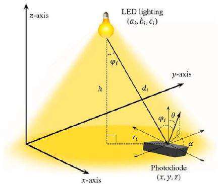
RSSI를 이용한 LED 조명기반 가시광통신 실내위치인식방법은 광원으로부터 떨어진 거리와 입사각, 방사각에 따라 수신된 광량의 차이를 이용한 방식이다. RSSI를 측정하여 송신부로부터 수신부가 떨어진 거리를 측위하기 위한 가시광채널 모델은 Figure 1과 같이 (ai,bi,ci)에 가시광통신이 가능한 LED 조명이 설치되어 있고, (x,y,z)에 광량을 측정이 가능한 수신기가 있으며 수신된 광 전력 PRx는 송신된 광 전력 PTx와 channel DC gain H(0)로 (1)과 같이 나타낼 수 있다식 [34].
| (1) |
channel DC gain H(0)는 식 (2)와 같이 나타나며 ψi는 입사각, φi는 방사각, Ts(ψ)는 광학 필터의 이득, g(ψ)는 광학 집중도의 이득, AR은 광다이오드(Photodiode)의 물리적 검출 영역, di는 송신기와 수신기의 직선거리, Ψc는 수신기의 FOV(Field of view)이고, m은 람버시안 계수로 m=ln2/ln(cosΦ1/2)과 같고 Φ1/2는 LED 방사의 반각을 나타낸다. 예를 들어 Φ1/2=60o일 경우 m=1이다. 광학 집중도 g(ψ)는 식 (3)과 같다. 여기에서, n은 반사 계수이다. 식 (2)에서 LED 조명 송신기와 수신기가 평행을 이루고, 천장에서 높이를 h라고 했을 때, cos(Φ)=cos(ψ)=h/d가 된다. 다시 식을 정리하면 식 (4)와 같다.
| (2) |
| (3) |
| (4) |
식 (4)를 이용하여 광도(Luminous intensity)와 높이가 일정하다면 수평거리 r을 구할 수 있게 되고 선형 LSM기반 삼변측량을 이용하여 수신기의 상대적인 위치를 구할 수 있다[13]. 그러나 송신기와 수신기가 평행하지 않다면 cos(Φ)≠cos(ψ)이기 때문에 입사각 ψi, 방사각 φi는 식 (5), 식 (6)과 같이 정의된다.
| (5) |
| (6) |
직선거리 d와 수신기의 법선벡터, 송신기의 법선벡터를 이용하여 각각 ψi, φi로 표현이 가능하다. θ는 수신기의 기울기각, α는 수신기의 방위각을 나타낸다.
2.2 Gauss-Newton 기법
Newton-Rapshon 기법은 식 (7)과 같은 하나의 변수에 대한 모델의 해를 근사적으로 구하기 위해 식 (8)과 같이 xk에서 접선이 x축 만나는 지점 xk+1으로 이동시키면서 점진적으로 해를 찾는 방법으로 수렴할 때까지 반복하여 수행한다.
| (7) |
| (8) |
Gauss-Newton 기법은 식 (9)와 같은 비선형 다변수 연립방정식의 근사해를 찾는 대표적인 방법이다. 식 (10)과 같이 Xk에서 접선이 X축과 만나는 지점 Xk+1으로 Jacobian 행렬을 이용하여 이동시키면서 점진적으로 해를 찾기 위해 수렴할 때까지 반복하여 수행한다.
| (9) |
| (10) |
X와 F는 각각 X=(x1,⋯,xn), F(X)=(f1,⋯fm) 의미하며, J는 Jacobian 행렬을 나타낸다.
3. RSSI 기반 가시광통신기반 3차원 위치인식
3.1 시스템구조
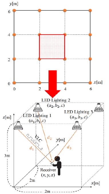
Figure 2는 실내 측위 시스템을 표현하였으며 6×6×3m3의 자유 공간에서 가로 2m, 세로 2m 간격으로 4×4 사각형 격자 패턴으로 높이3m에 설치된 VLC 송신 기능이 있는 LED 조명과 광 출력을 전력으로 변환 시켜주는 수신기를 나타낸다. 각각의 LED 조명의 위치는 고정되어있고, 수신기에서 받는 신호는 중첩된 LED 조명의 신호를 각각 측정이 가능하다. 수신기의 기울기와 방위를 고려한 3차원 공간에서 수신기의 위치를 찾는 방법에 대해 기술한다.
3.2 RSSI기반 가시광통신기반 3차원 위치인식
수신기의 위치를 측위하기 위해 가시광통신을 이용하여 각각 LED 조명 RSSI를 측정하고, 그중 상위 3개의 조명을 선정하여 측정된 세기를 가시광채널 모델을 이용하여 수신된 위치를 계산한다. Gauss-Newton 기법은 초기값 설정이 필요하며 초기값은 선형 LSM 기법을 이용하여 초기위치를 설정한다. 송신기와 수신기의 평행일 때 구하는 식 (4)를 이용하며, 높이 h는 제안한 공간상 제한으로 위치를 기점으로 바닥까지 3m로 설정한다. 3개의 LED 조명의 x,y 좌표는 (a1,b1),(a2,b2),(a3,b3)이며, 각 측정된 수평거리는 r1,r2,r3로 표현하였다.
식 (11)은 행렬 형식으로 표현이 가능하여, 식 (12)와 같이 표현되며, X=(ATA)-1ATB로 선형 LSM을 이용하여 수신기의 좌표 x,y를 추정할 수 있다. 그러므로 상대적인 수신기의 초기위치 (x0,y0,z0)는 식 (13)과 같이 LED 조명의 위치와 각 조명과 수신기간의 수평거리 r을 이용하여 구할 수 있다.
| (11) |
| (12) |
| (13) |
초기위치는 송신기와 수신기가 평행상태이기 때문에 높은 정확도를 가지지만 평행상태가 아닐 경우 낮은 정확도를 갖기 때문에 수신기의 기울기 및 방위각이 고려된 모델이 필요하다. 수신기의 기울기 및 방위각을 고려한 모델을 이용하여 위치 측정하기 위해서는 선형 LSM을 사용할 수 없기 때문에 이를 해결하기 위해 Gauss-Newton 기법을 이용하며 식 (14)와 같이 다변수 비선형 연립방정식의 함수 모델로 나타낸다. 각 LED 조명의 고정된 위치에서 수신기의 상대적인 직선거리는 가시광채널 모델을 이용하여 식 (15)와 같이 표현이 된다.
| (14) |
| (15) |
Gauss-Newton 기법에 의해 식 (16)과 같이 표현되며 반복적인 수행을 통하여 위치측위가 가능하다. J(X)는 Jacobian 행렬로 식 (17)과 같이 정의되며, X는 식 (18)과 같이 수신기의 위치를, F(X)는 식 (19)와 같이 3개의 LED 조명에서 수신된 상대적인 거리에 대한 식을 의미한다.
| (16) |
| (17) |
| (18) |
| (19) |
4. 실험 방법 및 결과
가시광 통신으로 인한 백색 잡음에 대하여 설명하고 제안한 방법의 타당성을 검증하기 위해 선형 LSM 삼변측량기법과 Gauss-Newton기법을 이용한 방법을 비교 및 분석한다.
4.1 실험 환경
VLC 채널에서 잡음 PN 요인은 shot noise, thermal noise, inter symbol interference이고 백색 잡음이다. 잡음 전력의 총합은
식 (19)와 같다. 식 (20) ~ 식 (22)은 잡음을 식으로 표현한 것이다.
| (20) |
| (21) |
| (22) |
| (23) |
식 (21)은 shot noise를 나타내고, q는 electronic charge, B는 equivalent noise bandwidth, Ib는 background current를 의미한다. 식 (22)은 thermal noise로 feedback-resistor noise와 FET channel noise의 합으로 나타나고, k는 볼츠만 상수, TK는 절대온도, G는 open-loop Voltage gain, η은 지역 단위당 PD의 고정된 capacitance, Γ은 FET channel noise factor, gm은 FET transconductance, I3 = 0.0868을 나타낸다. 시뮬레이션의 파라미터는 기존의 연구[18]를 참조하였으며 Table 1과 같다.
4.2 실험 방법
RSSI기반의 가시광통신을 이용한 위치인식 모의실험은 6×6×3m3의 자유 공간에서 수행하였으며 2가지 실험방법으로 나누어 결과를 분석한다. 첫 번째 실험은 수신기의 기울기각(Theta angle) 및 방위각(Alpha angle) 변화로 인한 제안한 위치인식 기법의 정확성을 검토하기 위해 수신기의 기울기각 및 방위각 변화에 따른 기존의 선형 LSM 삼변측량기법과 제안한 Gauss-Newton 기법을 이용한 위치인식 오차를 비교 및 분석한다. 두 번째 실험은 6×6×3m3의 자유 공간에서 가로, 세로 10cm단위로 3600개의 위치를 기준으로 기존의 선형 LSM 삼변측량기법과 제안한 위치인식기법의 정확성을 평균오차와 표준편차를 구한다.
4.3 실험 결과
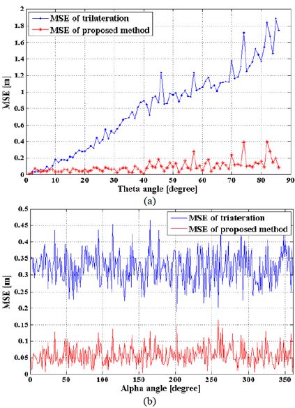
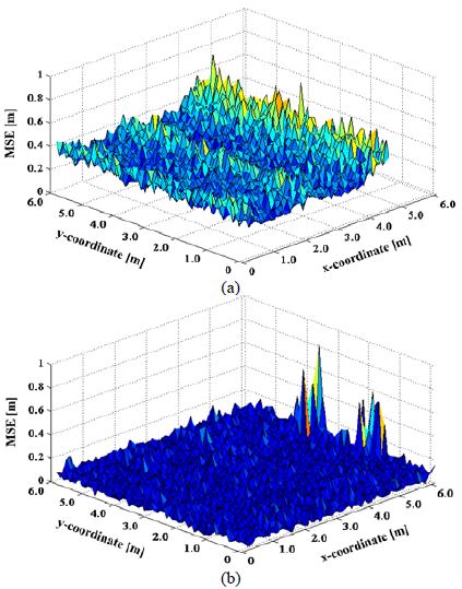
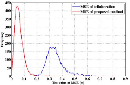
Figure 3은 제안된 실험공간에서 (3,3,0) 좌표의 위치에서 수신기의 기울기각(Theta angle) 및 방위각(Alpha angle) 변화로 인한 기존의 선형 LSM 삼변측량기법과 제안한 Gauss-Newton 기법을 이용한 위치인식 MSE(Mean Square Error) 결과를 나타낸다. Figure 3 (a)와 같이 방위각은 0°인 상태에서 기울기각의 변화에 따라 기존의 선형 LSM 삼변측량기법과 제안한 Gauss-Newton 기법의 MSE 결과 평균은 각각 0.8080m, 0.0948m이었으며 제안한 기법이 기존방식대비 0.7132m만큼 오차를 개선하는 것으로 나타났다. Figure 3 (b)와 같이 기울기는 20°인 상태에서 방위각의 변화에 따라 기존의 선형 LSM 삼변측량기법과 제안한 Gauss-Newton 기법의 MSE 평균은 각각 0.3209m, 0.0576m이었으며 제안한 기법이 기존방식 대비 0.2632m만큼 오차를 개선하는 것으로 나타났으나 방위각의 변화에 따라 MSE의 영향을 미치지 않는 것을 확인하였다. 그렇지만 실제 위치와 비교해본 결과 방향에 대한 위치오차가 발생한다. 이를 확인하기 위하여 실험 공간 x축, y축 각각 2~4m, 2~4m인 영역에서 0.40m 간격으로 36개의 위치에서 기울기각이 고정된 상태의 방위각 변화에 따른 기존의 선형 LSM 삼변측량기법과 제안한 Gauss- Newton 기법 추정위치를 비교 실험을 하였으며 그 결과는 Figure 4와 같다. Figure 4 (a)와 Figure 4 (b)는 방위각이 각각 0°, 120°일 때 추정된 위치결과를 실제 위치와 비교한 결과를 나타내며 방위각이 0°, 120° 일 때 MSE 평균은 기존의 LSM 삼변측량기법과 제안한 Gauss-Newton 기법을 비교해본 결과 각각 0.3218m, 0.05914m, 0.3323m, 0.05353m로 나타났다. 기존의 LSM 삼변측량기법은 실제 위치에서 방위에 따라 위치가 다소 일정한 한 방향으로 오차가 나타나는 것을 확인하였다. 제안한 수신기의 기울기 및 방위각을 고려한 Gauss-Newton 기법을 이용한 RSSI 측위 방법의 정밀도를 측정하기 위해 두 번째 실험은 6×6×3m3의 자유 공간에서 수신기의 기울기각이 20°, 방위각이 0°일 때 가로, 세로 10cm단위로 3600개의 위치를 기준으로 기존의 선형 LSM 삼변측량기법과 제안한 위치인식기법의 정확성을 분석하였다. Figure 5는 그에 대한 결과를 나타내며 Figure 5 (a), Figure 5 (b)는 각각 기존의 LSM 삼변측량기법과 Gauss-Newton 기법의 위치에 대한 MSE 결과를 나타내며 평균 0.3389m, 0.0594m이다. Figure 5x (a)와 같이 기존의 LSM 삼변측량기법은 LED 조명이 설치된 아래 부분에서 다른 위치에 비교하여 높은 오차를 보였으며 x축이 6m인 곳에서 가장 높은 오차를 보이는 것을 확인할 수 있었다. 기울기각과 방위각에 의해 형성된 오차로 주변 신호를 적게 받아 이러한 현상이 발생한다. 제안한 Gauss-Newton 기법은 Figure 5 (b)와 같이 수신기각 및 방위각을 고려하여 기존의 LSM 삼변측량기법에 비해 평균 0.2795m만큼 오차를 줄여 제안한 알고리즘 위치 정확도가 기존의 선형 LSM 삼변측량기법 대비 82.5% 개선되었다. Figure 5와 같이 나타난 결과를 오차의 분포도를 확인하기 위해 히스토그램을 이용하여 Figure 6에 나타냈으며, 오차 분포도에 따른 빈도수를 의미하고 위치인식 표준편차는 각각 0.0425, 0.0695로 제안한 기법이 기존의 방식보다 정밀한 오차 분포도를 나타낸다.
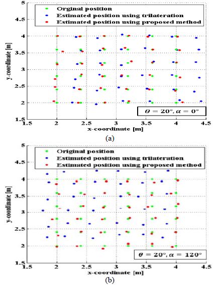
Estimated position result using trilateration and proposed method compared with original position when θ is 20° and (a) α = 0°, (b) α = 120°
5. 결 론
수신기의 기울기각 및 방위각 변화에 의한 수신기의 측위가 된 위치는 기존의 LSM 삼변측량기법을 이용한 경우 측위 오차가 발생하는 것을 확인할 수 있었다. 이에 따라 본 논문에서는 수신기의 기울기각 및 방위각 변화로 인한 비선형 위치 측위 모델을 해결을 위해 Gauss-Newton 기법을 사용하여 가시광통신기반 3차원 실내위치인식에 대한 알고리즘을 제안하였다. 제안한 시스템은 기울기각에 의하여 변한 신호들을 가시광 채널 비선형 모델과 Gauss-Newton 기법을 이용하여 수신기의 상대적인 위치를 추정할 수 있었다. 제안한 위치인식 시스템은 수신기로부터 수신된 RSSI를 선형 최소자승기법을 통해 수신기의 초기 위치를 선정하여 연산량을 줄이고 이를 기반으로 3차원비선형 모델을 적용하기 위하여 가우스-뉴턴 기법을 사용하여 정확도를 개선하였다. 위치인식 공간은 16개의 LED 조명을 설치한 6×6×3m3의 실내 공간에서 시뮬레이션을 수행하여 기존의 선형 LSM 삼변측량기법과 비교하여 수신기의 기울기각에 의한 차이를 MSE로 나타냈으며 방위각에 의한 변화를 실제 위치와 비교하여 나타냈고 전체적인 오차를 확인하므로 제안한 논문의 타당성을 검증하였다. 향후 위치추적단계에서 여러 필터를 이용하여 더욱 정밀한 위치측위에 대한 연구를 할 계획이다. 이러한 연구를 통하여 실내에서 가시광통신이 가능한 LED 조명 인프라를 이용하여 사용자가 수신기를 LED 조명과 평행이지 않은 상태에서도 정밀한 위치인식 및 가시광통신의 장점이 어울려져 LBS 시장을 확대할 수 있을 것으로 전망된다.
Acknowledgments
“이 논문은 2016년도 한국마린엔지니어링학회 전기학술대회에서 발표된 논문을 개선한 것이며 2015년도 중소기업청의 지원을 받아 수행된 창업성장-1인창조 사업임 (No. S2292553)”
References
- H. J. Kwon, M. G. Kim, Y. S. Kim, and S. G. Lee, “Lifetime test of batteries for BLE modules for site identification of vessel’s crews and passengers (SIVCP),”, Journal of the Korean Society of Marine Engineering, 39(7), p754-759, (2015), (in Korean).
-
W. O. Kim, J. S. Kim, and W. C. Park, “Improvement of citadel structure on board ship using FDS,”, Journal of the Korean Society of Marine Engineering, 39(3), p306-311, (2015), (in Korean).
[https://doi.org/10.5916/jkosme.2015.39.3.306]

-
W. O. Kim, J. S. Kim, and W. C. Park, “A study on the improvement of survival rate of the passengers and crews according to FDS analysis,”, Journal of the Korean Society of Marine Engineering, 39(3), p312-317, (2015), (in Korean).
[https://doi.org/10.5916/jkosme.2015.39.3.312]

-
H. J. Kwon, H. S. Yang, and S. G. LEE, “Site monitoring of crews and passengers on board by the BLE and PLM combination,”, Journal of the Korean Society of Marine Engineering, 39(4), p463-467, (2015), (in Korean).
[https://doi.org/10.5916/jkosme.2015.39.4.463]

- G. W. Yim, S. H. Lee, S. Y. Kim, and N. S. Kang, “Development of unified communication for marine VoIP service,”, Journal of the Korean Society of Marine Engineering, 39(7), p744-753, (2015), (in Korean).
- J. H. Koo, and K. I. Hwang, “A Koreans’ consciousness survey on the onboard safety of domestic passenger ship,”, Journal of the Korean Society of Marine Engineering, 38(4), p495-501, (2014), (in Korean).
-
K. I. Hwang, “Comparative study on predictions of passengers’ evacuation performances before and after the remodelling of MV SEWOL,”, Journal of the Korean Society of Marine Engineering, 39(1), p105-114, (2014), (in Korean).
[https://doi.org/10.5916/jkosme.2015.39.1.105]

-
Z. Deng, Y. Yu, X. Yuan, N. Wan, and L. Yang, “Situation and development tendency of indoor positioning,”, China Communications, 10(3), p42-55, (2013).
[https://doi.org/10.1109/CC.2013.6488829]

- C. H. Huang, L. H. Lee, C. C. Ho, L. L. Wu, and Z. H. Lai, “Real-time RFID indoor positioning system based on Kalman-filter drift removal and Heron-bilateration location estimation,”, IEEE Transactions on Instrumentation and Measurement, 64(3), p728-739, (2015).
-
H. Liu, H. Darabi, P. Banerjee, and J. Liu, “Survey of wireless indoor positioning techniques and systems,”, IEEE Transactions on Systems, Man, and Cybernetics, 37(6), p1067-1080, (2007).
[https://doi.org/10.1109/TSMCC.2007.905750]

-
C. Yang, and H. R. Shao, “WiFi-based indoor positioning,”, IEEE Communications Magazine, 53(3), p150-157, (2015).
[https://doi.org/10.1109/MCOM.2015.7060497]

-
J. H. Seong, T. W. Lim, J. S. Kim, S. G. Park, and D. H. Seo, “An improvement algorithm for localization using adjacent node and distance variation analysis techniques in a ship,”, Journal of the Korean Society of Marine Engineering, 37(2), p213-219, (2013), (in Korean).
[https://doi.org/10.5916/jkosme.2013.37.2.213]

-
J. H. Kim, S. G. Lee, J. S. Kim, J. W. Kim, and D. H. Seo, “A study on indoor navigation system using localization based on wireless communication,”, Journal of the Korean Society of Marine Engineering, 37(1), p114-120, (2013), (in Korean).
[https://doi.org/10.5916/jkosme.2013.37.1.114]

-
J. H. Seong, J. S. Park, S. H. Lee, and D. H. Seo, “Indoor localization algorithm based on WLAN using modified database and selective operation,”, Journal of the Korean Society of Marine Engineering, 37(8), p932-938, (2013), (in Korean).
[https://doi.org/10.5916/jkosme.2013.37.8.932]

-
H. J. Cho, J. S. Kim, S. G. Lee, J. W Kim, and D. H. Seo, “Fixed node reduction technique using relative coordinate estimation algorithm,”, Journal of the Korean Society of Marine Engineering, 37(2), p220-226, (2013), (in Korean).
[https://doi.org/10.5916/jkosme.2013.37.2.220]

-
J. H. Kim, H. J. Kim, J. S. Kim, S. G. Lee, and D. H. Seo, “An indoor localization approach using RSSI and LQI based on IEEE 802.15.4,”, Journal of the Korean Society of Marine Engineering, 38(1), p92-98, (2014), (in Korean).
[https://doi.org/10.5916/jkosme.2014.38.1.92]

-
J. H. Kim, H. J. Kim, J. S. Kim, S. G. Lee, and D. H. Seo, “Relative azimuth estimation algorithm using rotational displacement,”, Journal of the Korean Society of Marine Engineering, 38(2), p188-194, (2014).
[https://doi.org/10.5916/jkosme.2014.38.2.188]

- H. J. Cho, S. G. Lee, W. H. Cho, D. S. Noh, and D. H. Seo, “Self-positioning fusion system based on estimaion of relative coordinates,”, Journal of the Korean Society of Marine Engineering, 38(5), p566-572, (2014).
-
J. H. Kim, J. H. Sung, Y. S. Ha, and D. H. Seo, “Improved adaptive smoothing filter for indoor localization using RSSI,”, Journal of the Korean Society of Marine Engineering, 39(2), p179-186, (2015).
[https://doi.org/10.5916/jkosme.2015.39.2.179]

-
H. J. Cho, W. Y. Kim, Y. I. Joo, and D. H. Seo, “Robust relative localization using a novel modified rounding estimation technique,”, Journal of the Korean Society of Marine Engineering, 39(2), p187-194, (2015).
[https://doi.org/10.5916/jkosme.2015.39.2.187]

-
K. R. Sohn, “Implementation of the equalization circuits for high bandwidth visible light communications using phosphorescent white LED,”, Journal of the Korean Society of Marine Engineering, 39(4), p473-477, (2015), (in Korean).
[https://doi.org/10.5916/jkosme.2015.39.4.473]

-
M. S. Kim, and K. R. Sohn, “Performance investigation of visible light communication using super bright white LED and fresnel lens,”, Journal of the Korean Society of Marine Engineering, 39(1), p63-67, (2015), (in Korean).
[https://doi.org/10.5916/jkosme.2015.39.1.63]

-
M. S. Kim, and K. R. Sohn, “Implementation of underwater visible light communication system interlinked with bluetooth”, Journal of the Korean Society of Marine Engineering, 38(7), p923-928, (2014), (in Korean).
[https://doi.org/10.5916/jkosme.2014.38.7.923]

-
K. R. Sohn, “Performance analysis of the visible light communication in seawater channel,”, Journal of the Korean Society of Marine Engineering, 37(5), p527-532, (2013), (in Korean).
[https://doi.org/10.5916/jkosme.2013.37.5.527]

-
K. R. Sohn, “A study on the short-range underwater communication using visible LEDs,”, Journal of the Korean Society of Marine Engineering, 37(4), p425-430, (2013), (in Korean).
[https://doi.org/10.5916/jkosme.2013.37.4.425]

- W. Y. Kim, H. C. Zin, J. C. Kim, and D. H. Seo, “A study on indoor visible light communication positioning using RSS according to variation of receiving angle,”, Proceedings of the 40th KOSME Spring Conference, p111, (2016), (in Korean).
- X. Sun, Y. Zou, J. Duan, and A. Shi, “The positioning accuracy analysis of AOA-based indoor visible light communication system,”, IEEE International Conference on Optoelectronics and Microelectronics (ICOM), p186-190, (2015).
-
T. O. Wang, Y. A. Sekercioglu, A. Neild, and J. Armstrong, “Position accuracy of time-of-arrival based ranging using visible light with application in indoor localization systems,”, Journal of Lightwave Technology, 31(20), p3302-3308, (2013).
[https://doi.org/10.1109/JLT.2013.2281592]

-
T. H. Do, and M. Yoo, “TDOA-based indoor positioning using visible light,”, Photonic Network Communications, 27(2), p80-88, (2014).
[https://doi.org/10.1007/s11107-014-0428-4]

-
W. Y. Kim, S. G. Park, W. H. Cho, D. S. Noh, and D. H. Seo, “A study on indoor visible light communication localization based on manchester code using walsh code,”, Journal of the Korean Society of Marine Engineering, 39(9), p959-966, (2015), (in Korean).
[https://doi.org/10.5916/jkosme.2015.39.9.959]

- S. Yamaguchi, V. V. Mai, T. C. Thang, and A. T. Pham, “Design and performance evaluation of VLC indoor positioning system using optical orthogonal codes,”, 5th IEEE International Conference on Communications and Electronics(ICCE), p54-59, (2015).
-
D. Y. Kim, and K. Y. Yi, “RSSI-based indoor localization method using virtually overlapped visible light,”, The transactions of The Korean Institute of Electrical Engineers, 63(12), p1697-1703, (2014), (in Korean).
[https://doi.org/10.5370/KIEE.2014.63.12.1697]

- A. Şahin, Y. S. Eroğlu, I. Güvenç, N. Pala, and M. Yüksel, “Hybrid 3-D localization for visible light communication systems,”, Journal of Lightwave Technology, 33(22), p4589-4599, (2015).
-
T. Komine, and M. Nakagawa, “Fundamental analysis for visible-light communication system using led lights,”, IEEE Transactions on Consumer Electronics, 50(1), p100-107, (2004).
[https://doi.org/10.1109/TCE.2004.1277847]


