스트레인 게이지를 이용한 5만 DWT 석유화학제품 운반선의 횡진동 분석에 관한 연구


Copyright © The Korean Society of Marine Engineering
This is an Open Access article distributed under the terms of the Creative Commons Attribution Non-Commercial License (http://creativecommons.org/licenses/by-nc/3.0), which permits unrestricted non-commercial use, distribution, and reproduction in any medium, provided the original work is properly cited.
초록
추진축계 횡진동은 축계배치계산과 함께 설계단계에서 충분한 검토가 이루어져야 한다. 축계 강제 횡진동 문제는 아직 명쾌한 해석방법이 제시되지 못하고 있으며 선급, 국제규격 등에서 대략적으로 프로펠러 날개차수 고유 진동수가 엔진정격회전수의 ±20%이내에 들지 못하게 하고 있다. 축계배치관점에서는 축계 지지베어링 중심간 사이의 거리가 멀수록 좋으나 횡진동관점에서는 파장이 길어지고 고유진동수는 낮아져 공진이 발생할 수 있는 요인이 되어 검토시 주의가 요구되므로 계산결과를 실측으로 검증하는 것이 바람직하다. 본 연구에서는 최근 친환경 고효율 선박으로 등장한 5만 DWT급 석유화학제품운반선을 대상으로 횡진동 이론적 분석 및 스트레인 게이지 계측자료 분석을 수행하고 이를 통해 횡진동이 추진축계에 미치는 영향을 검토하였다.
Abstract
During the initial stage of propulsion shaft design, the shaft alignment process includes a thorough consideration of lateral vibration to verify the operational safety of the shaft. However, a theoretical method for analyzing forced lateral vibrations has not been clearly established. The methods currently used in classification societies and international standards can only ensure a sufficient margin to avoid the blade-passing frequency resonance speed outside the range of ±20% of the maximum continuous rating (MCR) for the engine. Typically, in shaft alignment analyses, longer center distances between the support bearings promote affirmative results, but the blade order resonance speed can approach the lower limit for lateral vibration. Therefore, this matter requires careful attention by engineers, and a verification of the theoretical analysis by experimental measurements is highly desirable. In this study, both theoretical and experimental analyses were conducted using strain gauges under two draught conditions of vessels used as 50,000-DWT oil/chemical tankers, introduced recently as eco-friendly ships. Based on the analyses, the influence of the lateral vibration on the shafting system and the system’s reliability was reviewed.
Keywords:
Lateral vibration, Blade passing frequency, Strain gauge키워드:
축계 횡진동, 날개차수 고유진동수, 스트레인 게이지1. 서 론
선박 추진축계의 횡진동 문제는 1950년대 미국해군에 의해 시작된 추진축계 정렬문제와 연계하여 Panagopulos[1]에 의한 계산식이 발표된 것을 시작으로 횡진동에 관한 연구가 상당수 이루어졌다. 그 중에서도 가장 주목할 만한 것이 Jasper[2]-[4]에 의해 수행된 일련의 연구이며 이로 인해 축계 횡진동의 고유진동수 계산, 프로펠러 날개차수 진동의 공진회피에 대한 설계적 배려도 어느 정도 가능하게 되었다. 국내에서는 1970년대 말부터[5]-[11] 축계 횡진동 관련 연구가 시작되었으며 1990년대에는 선박의 대형화와 에너지절감 및 추진효율 개선을 위하여 낮은 기관 운전속도와 대형 프로펠러를 채용하기 시작함으로써 프로펠러 날개차수 고유진동수가 상용회전수까지 내려올 가능성이 발생하게 됨에 따라 추진축의 선회 임계속도에 관한 연구가 수행된 바 있다[12]. 이를 통해 현재 각 조선소에서는 간단한 축계 정보 입력만으로 횡진동 계산을 수행함으로써 횡진동 문제는 고유진동수 관점에서 대부분 문제없이 해결하고 있는 상황이다.
그러나 횡진동 강제진동 해석과 관련된 연구는 축계 지지베어링의 강성 및 유막 강성, 프로펠러 기진력 등의 불분명한 요소들로 인해 아직까지도 난제로 남아 있다. 따라서 현재까지는 선급, 국제규격 등에서 프로펠러 날개차수 고유진동수가 엔진 정격회전수의 ±20%이내에 들지 못하도록 하는 제한치[13] 대비 충분한 마진을 확보했는지 여부를 자유진동관점에서 확인하는 수준이다. 또한 축계배치관점에서는 축계 지지베어링 중심간 사이의 거리가 멀수록 좋으나 횡진동 관점에서는 파장이 길어지고 고유진동수는 낮아져 공진이 발생할 수 있는 또 다른 요인이 되어 검토 시 주의가 요구되므로 이러한 상황을 고려할 때 횡진동 고유진동수 계산결과를 실측으로 검증하는 것이 바람직하다. 이와 관련하여 그간 변위센서 및 스트레인 게이지를 이용하여 횡진동이 추진축계에 미치는 영향분석에 관한 연구가 간헐적으로 수행[14]-[18]되었지만 최근 등장한 5만톤급 석유화학제품 운반선(MR tanker)에 대한 연구사례는 아직까지 보고되지 않았다. 본 연구의 대상선박인 5만톤급 MR 탱커는 유사선 대비 새로운 형식의 기관을 탑재하고 부하경감 기술(De-rating)을 적용하여 엔진회전수를 낮추면서 연료 소모량을 크게 절감하였으며 이로 인해 낮아진 선속을 직경이 증가된 프로펠러 적용으로 보상하여 추진효율을 극대화 시킨 친환경 고효율 선박이다. 본 연구에서는 5만톤급 MR탱커에 대하여 횡진동 고유진동수 계산 및 스트레인 게이지 계측자료 분석을 통하여 횡진동 영향 하에서의 추진축계 안정성을 검토하였다.
2. 횡진동 계산 및 해석방법
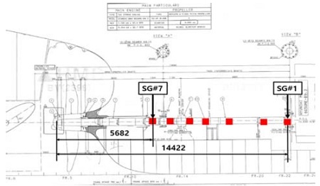
Table 1은 본 연구에 이용한 실선의 축계 주요 사양이며 Figure 1은 축계 배치도 및 굽힘응력 측정을 위한 스트레인 게이지 부착위치를 나타내었다.
횡진동 고유진동수 계산은 LATMODE 및 Endyn 프로그램을 사용하였으며 근사계산법으로 수정 Panagopulos법 및 Jasper-Rayleigh 법을 사용하였고 정밀계산법으로 유한요소법을 사용하였다. 또한 프로펠러의 부가수 효과 및 감쇠는 수정 Schwanecke 공식을 사용하고 유막, 베어링, 베어링 받침대의 강성이 포함된 베어링의 강성은 Table 2와 같이 주기관 및 베어링 제작사의 자료를 참고하였다. 여기서 STB, IB, MB는 각각 선미관베어링, 중간축베어링, 주기관베어링을 의미한다.
이를 통해 횡진동 회전수 1차 성분 및 날개차수 성분의 공진점을 계산하였다.
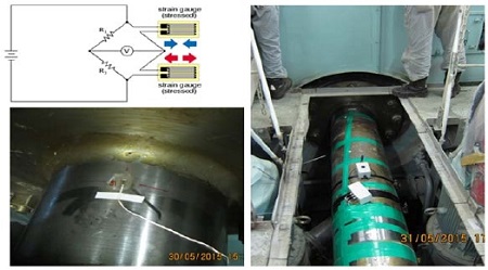
아울러 계산결과와의 비교 검증을 위해 스트레인 게이지를 이용하여 굽힘응력 측정을 수행하였다. 스트레인 게이지는 기관실 선미격벽에 가장 가깝게 설치된 스트레인 게이지를 SG#7로 하고 이를 기준으로 엔진쪽으로 축의 종방향에 걸쳐 설치하였으며 원격측정장치(telemetry)로 구성하여 선박 운전상태시의 동적 굽힘응력을 확인할 수 있도록 하였다. 통상 계측은 횡진동으로 인한 축계의 응력진폭이 최대가 될 것으로 예상되는 지점을 측정위치로 선정하여 수행하는 것이 가장 이상적이나 해당 지점은 선체 외부의 프로펠러 질점에 해당하므로 차선책으로써 진폭 비가 기관실 내에서 가장 높을 것으로 예상되는 SG#7위치에서 계측을 수행하였다. 스트레인 게이지와 원격측정장치의 구성을 Figure 2에 나타내었다.
본 연구에서는 TML(Tokyo sokki kenkyujo)사의 스트레인 게이지(model: WFLA-3-11-L1)를 사용하여 하프 휘트스톤 브릿지(half-wheatstone bridge) 방식으로 구성하였고 게이지는 2개를 1조로 하여 해당 위치의 축 상단 및 하단에 180도 간격으로 부착하였다. 굽힘응력 값을 취득하는 방법은 다음과 같다. 축 표면에 부착된 스트레인 게이지의 저항값은 축 회전시 발생하는 축의 수직 변형률에 비례하여 변동되는데 이러한 저항값의 변화로 입력전압 대비 변동된 출력전압을 얻을 수 있다. 이를 통해 식 (1)과 같은 하프 휘트스톤 브리지 결선 방식에서의 변형률을 얻을 수 있다.
| (1) |
여기에서 Vo는 휘트스톤 브릿지에서 측정된 출력전압 값이고 Vek는 입력전압이다. 본 연구에서는 대략적으로 10V의 Vek값이 사용되었다. k는 스트레인 게이지 상수이다. 따라서 스트레인 게이지로부터 수신된 변형율과 축 재료의 종탄성계수 E를 이용하면 식 (2)와 같이 축의 굽힘응력을 구할 수 있다.
| (2) |
계측은 주기관의 2~5 rpm간격으로 수행되었으며 아래 조건에 따라 각각 수행되었다.
C1: Scantling draught APT full (aft: 12.6m fore: 13.2m)
C2: Ballast draught APT empty (aft: 7.9m fore: 6.3m)
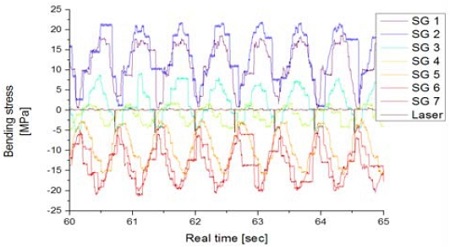
Figure 3은 C2 조건의 MCR 상태에서 계측된 굽힘응력 선도 예를 보여준다.
다음으로 운전상태에서 취득된 시간기반(time-domain)파형을 관찰하고 고속 푸리에 변환(FFT)을 이용한 주파수 스펙트럼 분석을 수행하였다. 또한 스펙트럼을 차수 추적(order tracking)하여 횡진동과 밀접한 관계에 있는 1차(1X), 4차(4X), 8차(8X)성분들을 분리하여 회전속도 변화에 따른 각 주파수 성분들을 분석하였다. 마지막으로 주파수 스펙트럼을 회전수에 대해 연속 중첩하여 회전수 변화에 따른 축계의 횡진동 양상의 변화를 분석하였다.
3. 결과 및 고찰
먼저 횡진동 고유진동수 계산결과는 Table 3과 같다. 검토결과 모든 조건에서 1절4차(프로펠러 날개차수)의 공진회전수는 엔진정격최대출력회전수(MCR) 대비 최소 163.8% 이상 영역에 위치함으로서 제한치(±20%)를 상회하는 것으로 나타났다. 따라서 자유진동 측면에서 대상선박의 프로펠러축 회전수는 계산된 횡진동 고유진동수에 비하여 충분히 낮으므로 축계는 횡진동으로 인한 부정적인 영향을 받지 않을 것으로 판단되었다.
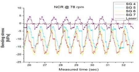
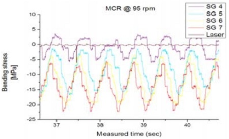
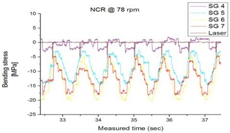
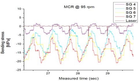
다음으로 운전상태에서 취득된 시간파형을 관찰하였다. Figure 4 ~ Figure 7에서는 C1, C2 조건하에서 NCR/MCR 근방(78/95 rpm)의 시간파형 선도를 나타내었다. 관찰 결과 전반적으로 위상이 일정하고 동일한 형태의 파형이 계속 반복되는 정현파 형태의 분수조화(subharmonics)진동 패턴을 보이는 바 선박의 운전영역에서 횡진동으로 인한 비정상적인 과도상태나 짧은 과도 충격(transient impulse)현상 등은 나타나지 않는 것으로 판단되었다.
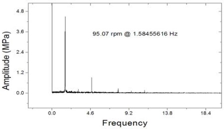
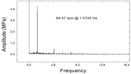
시간파형 관찰의 다음 단계로 C1 및 C2 조건에서 2~5 rpm 간격으로 측정한 데이터를 고속 푸리에 변환(FFT) 처리하여 주파수기반(frequency-domain) 스펙트럼 분석을 수행하였다. Figure 8 및 Figure 9에 대표적으로 C1 및 C2 조건별로 MCR 지점에서의 주파수 스펙트럼 분석 결과를 나타내었다.
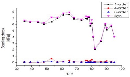
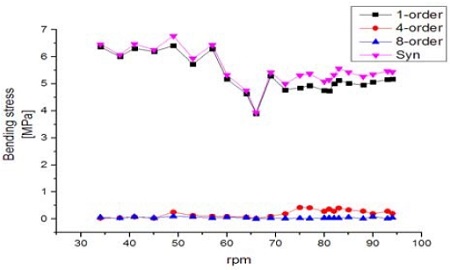
분석결과 회전수 1차 진동성분이 다른 성분에 비해 지배적으로 나타나고 있음을 확인하였다. 이는 횡진동 1차기진력의 주된 기진원인 프로펠러의 불평형력 및 곡선배치된 축계정렬 방식에서 기인한 프로펠러축 자체의 run-out효과가 작용하기 때문인 것으로 판단된다. 프로펠러 날개차수 성분(4X)은 회전수 1차성분에 비해 엔진 전 회전수 구간에서 현격히 낮은 수준으로 나타났다. 이는 짝수 프로펠러 채용에 따라 프로펠러축에 미치는 굽힘 모멘트가 상대적으로 홀수날개에 비해 작은점[19], 계측위치가 프로펠러 위치가 아닌 기관실 후단격벽에 위치한 점 등이 프로펠러 날개차수 성분이 낮게 나타난 원인이라고 추정할 수 있다. 보다 상세한 검토을 위하여 주파수 기반 스펙트럼을 횡진동과 밀접한 관계에 있는 1차(1X), 4차(4X), 8차(8X) 의 차수성분으로 분리하여 각 주파수 성분들을 회전속도의 변화(rpm-domain)에 따라 분석하여 Figure 10 및 Figure 11에 C1 및 C2 조건별로 나타내었다.
분석결과 회전수 1차성분의 경우 대체로 rpm에 관계없이 일정한 응답을 나타내고 있는데 이는 횡진동의 영향이라기보다는 곡선배치 축계정렬로 인한 축계 자체가 지닌 run-out 값의 영향인 것으로 추정된다. 다만, C1 조건의 81~90 rpm, C2 조건의 57~66 rpm 구간에서 일시적으로 굽힘응력이 감소되는 경향이 나타나는데 이는 선박의 운항 중 발생하는 서로 다른 진동의 기진원이 연성되어 기진력의 상쇄효과가 나타난 현상으로 추정된다. 또한 차수추적을 통해 특정 rpm에서 발생하는 공진점을 토대로 운전영역 밖에 위치하는 횡진동 고유진동수를 평가하고자 하였지만 본 계측구간에서 주목할 만한 공진점은 나타나지 않았다. 그러므로 위험회전수는 이론적계산에 따라 판단하여도 무방할 것으로 판단된다.
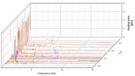
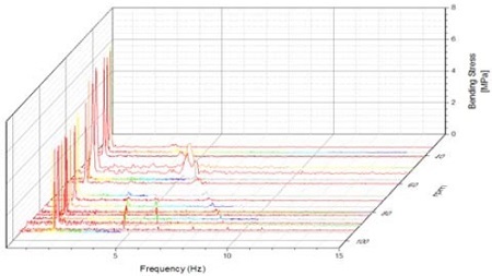
마지막으로 회전수 변화에 따른 축계의 횡진동 양상의 변화를 분석하기 위하여 C1 및 C2 조건별로 주파수 스펙트럼을 회전수에 대해 연속 중첩하여 Figure 12 및 Figure 13과 같이 폭포선도(waterfall plot)로 나타내었다.
분석결과 40~ 60 rpm 영역에서는 회전수 6차성분이 유의미하게 나타나는 것을 확인할 수 있는데 이는 비들림진동 위험회전수구간(47~57 rpm)통과시 발생하는 주기관 6차 성분과의 연성진동이 발생하기 때문인 것으로 판단된다. 또한 응력진폭이 1차 및 6차성분에 비해 낮기는 하나 C1 조건에서의 프로펠러 차수 성분(4X)이 C2 조건 대비 비교적 선명하게 검출되는 것을 확인할 수 있는데 이는 날개수 4매 프로펠러의 경우 평균 토크에 대한 수평 굽힘 모멘트가 밸러스트 흘수 상태에서 더 크게 작용하기 때문인 것으로 판단된다. 문헌[20]에 따르면 평온한 해역에서 평균적으로 발생하는 대단부의 반복 응력은 30 MPa 정도이며 경흘수에서 50 MPa, 황천시에는 60∼90 MPa 정도이다. 상기사항을 종합하여 판단할 때 측정된 굽힘응력은 발표된 실측결과 대비 10% 수준에 불과하므로 본 선박의 전 운항영역에서의 횡진동에 의한 공진현상은 발생하지 않는 것으로 판단된다.
4. 결 론
본 연구에서는 새로운 선형인 5만톤급 중형화학제품운반선에 대한 횡진동 고유진동수계산 및 스트레인게이지 계측자료 분석을 수행하고 이를 통해 다음과 같은 결론을 얻었다.
- 1) 횡진동 고유진동수 계산결과 공진회전수는 MCR 대비 최소 163.8% 이상 영역에 위치함으로서 제한치(±20%)를 상회하는 것으로 나타났다.
- 2) 취득된 시간파형 관찰 결과 횡진동으로 인한 비정상적인 과도상태나 짧은 과도 충격(transient impulse)현상 등은 나타나지 않는 것으로 판단되었다.
- 3) 회전수 1차성분의 경우 대체로 rpm에 관계없이 일정한 응답을 나타냈는데 이는 축 자체가 지닌 run-out 값 때문인 것으로 판단된다.
- 4) 40~ 60 rpm 영역에서 회전수 6차성분이 나타나는 것을 확인할 수 있는데 이는 위험회전수구간(47~57 rpm)통과 시 비틀림진동 6차 성분과의 연성진동이 발생하기 때문인 것으로 판단된다.
- 5) 측정된 굽힘응력은 발표된 실측결과 대비 10% 수준에 불과하므로 본 선박의 주요 운전영역에서 축계는 횡진동으로 인한 부정적인 영향을 받지 않을 것으로 판단된다.
References
- E. Panagopulos, “Design-stage calculations of torsional, axial and lateral vibrations of marine shafting”, Transactions of Society of Naval Architects and Marine Engineers, 58, p329-384, (1950).
- N. H. Jasper, A Theoretical Approach to the Problem of Critical Whirling Speeds of Shaft-Disk Systems, DTMB Report 890, David Taylor Model Basin Washington D. C., America, (1954).
- N. H. Jasper, A Design Approach to the Problem of Critical Whirling Speeds of Shaft-Disk Systems, DTMB Report 890, David Taylor Model Basin Washington D. C., America, (1954).
- N. H. Jasper, and L. A. Rupp, “An experimental and theoretical investigation of propeller shaft failures”, The International Journal of Society of Naval Architects and Marine Engineers, Transaction, 60, p314-381, (1952).
- H. J. Jeon, and H. C. Kim, “Calculation of transverse vibration of Ship`s Propulsion Shaftings by the Finite Element Method”, Journal of the Korean Society of Marine Engineering, 3(1), p2-18, (1979), (in Korean).
- S. Y. Ahn, and H. J. Jeon, “Calculation of the coupled free, transverse vibration of the multi-supported shaft system by transfer matrix method”, Journal of the Korean Society of Marine Engineering, 7(1), p49-63, (1983), (in Korean).
- S. Y. Ahn, “Coupled transverse vibrations of propeller-shaft systems”, Journal of the Society of Naval Architects of Korea, 22(2), p38-44, (1985), (in Korean).
- S. Y. Ahn, “Coupled free lateral vibration analysis of shafting by the finite element method”, Journal of the Society of Naval Architects of Korea, 23(4), p19-24, (1986), (in Korean).
- K. T. Yu, and H. J. Jeon, “A theoretical calculation of coupled free, tranverse vibration of the multi-supported shaft system by finite element method”, Journal of the Korean Society of Marine Engineering, 10(4), p41-49, (1986), (in Korean).
- S. Y. Ahn, “On the lateral vibration of propeller shaft systems”, Journal of the Korean Society of Marine Engineering, 13(1), p13-23, (1989), (in Korean).
- D. C. Lee, B. H. Park, and H. J. Jeon, “A study on the coupled forced lateral vibration of multi-supported shafting by the transfer matrix method”, Journal of the Korean Society of Marine Engineering, 14(2), p35-47, (1990), (in Korean).
- Y. C. Kim, and G. D. Lee, “A study on th whirling critical speeds of marine propeller shafts”, Journal of the Society of Naval Architects of Korea, 31(2), p29-37, (1994), (in Korean).
- American Bureau of Shipping, Rules for Building and Classing Steel Vessels Pt 4 Ch3 Sec2, Propulsion Shafting 7.9, TX, USA, ABS, (2015).
-
C. Y. Son, K. S. Lee, and Y. H. Ryu, “A study on the vibration characteristics of critical speed for rotor shaft”, Journal of the Korean Society for Noise and Vibration Engineering, 18(9), p961-971, (2008), (in Korean).
[https://doi.org/10.5050/KSNVN.2008.18.9.961]

- H. Kwun, Y. S. Han, and J. K. Eom, “Whirling vibration analysis & measurement of the propulsion shafting system of 1000p ro-ro ferry”, Proceedings of the Korean Society for Noise and Vibration Engineering 11th spring conference, p143-148, (2001), (in Korean).
- J. H. Kim, J. S. Kim, T. U. Kim, and D. C. Lee, “Measurement and assessment of whirling vibration using strain gauge in small propulsion shafting system”, Proceedings of the Korean Society for Noise and Vibration Engineering 21st spring conference, p527-532, (2011), (in Korean).
- J. N. Kim, H. Kwun, N. J. Park, S. Y. Song, and S. T. Choi, “Research on whirling vibration characteristics of propulsion shaft of ship with CPP”, Proceedings of the Korean Society for Noise and Vibration Engineering 23st spring conference, p879-881, (2013), (in Korean).
-
J. S. Sun, T. M. Han, K. K. Lee, and U. K. Kim, “A study on the measurement and analysis of whirling vibration behavior of marine propulsion shafting system using gap-sensors”, Journal of the Korean Society of Marine Engineering, 39(2), p130-135, (2015).
[https://doi.org/10.5916/jkosme.2015.39.2.130]

- Korean Register(KR), Control of Ship Vibration and Noise, 3rd ed, Korea, Textbooks, (2014), (in Korean).
- H. J. Jeon, Ship Propulsion Transmission Equipment, Busan, Korea, Taehwa Publishing Company, (1986), (in Korean).

