15kW-class wave energy converter floater design and structural analysis
Copyright © The Korean Society of Marine Engineering
This is an Open Access article distributed under the terms of the Creative Commons Attribution Non-Commercial License (http://creativecommons.org/licenses/by-nc/3.0), which permits unrestricted non-commercial use, distribution, and reproduction in any medium, provided the original work is properly cited.
Abstract
This study concentrates on the design of floater for 15kW-class wave energy converter that extracts the ocean energy by oscillating vertically along the wave motion. The floater connects to a arm structure that connects to a hydraulic cylinder, which drives a hydraulic generator. The study mainly focuses on the structural analysis of the floater. Previous studies have been conducted using a miniature model; however, this study focuses on the size selection of the floater for a full scale model. Static structural analysis is conducted using fine numerical grids. Due to the complexity of the whole model, it is analyzed as a separate component. There are several load cases for each floater size, and they are analyzed thoroughly for stress (von-mises, shear, and normal) and deformation. The initial design was conducted by scaling up from the miniature model of the previous study, and the final design has been redesigned by changing the thickness and internal support structure shape.
Keywords:
Wave energy converter, Floater, Stress, Deformation, Structure analysis1. Introduction
Ocean waves come in several sizes and forms, depending on the magnitude of the forces acting on the water. The gravitational attraction of the moon, sun, and other astronomical bodies creates the ocean waves and the tides. These waves travel around the world from end to end with enormous speeds [1]. Though ocean energy is still in a developmental stage, researchers are seeking ways to capture that energy and convert it to electricity.
The focus of this study has been on the ocean wave energy extraction by suggesting the use of floaters on a platform that follows the vertical wave motion to extract energy and convert it to electricity via a hydraulic generator. The study specifically focuses on the floater design by varying thickness and comparison to a new design that differs in internal structural support structures.
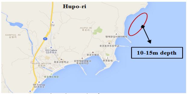
Korean seas have sufficient wave energy for applying a wave energy converter. Figure 1 show one suggested test site for this wave energy converter and also describes the water depth in this region. Depths ranging between 10-15 m can be found in the Hupo-ri region. In addition, the maximum wave heights are about 3.5 m and frequent wave heights close to 1 m, which is very suitable for this type of application [2][3].
2. Floater Model and Numerical Method
2.1 Floater design
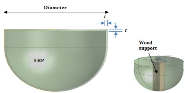
The floater design was conducted by scaling up the previous study design [3]. The previous study was a simple design using a semi-hemisphere made of fiber reinforced plastic (FRP) and supported on its center by a wood support as shown in Figure 2. Table 1 shows the four cases of different floater sizes suggested for the full scale Wave Energy Converter (WEC) model with its varying thickness of FRP. For each size, the scaling factor was calculated. The scale factor was determined from the suggested diameter sizes. The initial diameter of the miniature model was 1.2 m, and there were four suggested diameters for the full scale model (2.5, 3.0, 4.0, and 6.0 m). The scale factor was multiplied by the miniature floater thickness to get the thickness of the full scale model. The arm, flange, and wood support were also scaled using the same factor.
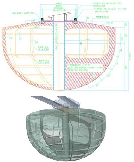
Revolving joints are applied to the arm and platform connection by the use of hinges. The platform also consists of upper and lower stoppers that prevent the arm from crashing into the platform. All the connections are done by pins, bolts and nuts. Permanent joints are connected through welding. The arm connects to the floater by using bolts and a flange head connector made of steel as shown in Figure 3[2]. The final floater was made of urethane foam and had an FRP thickness of 9 mm with a 0.3 m diameter PVC cylinder in the center providing added support.
2.2 Numerical method
Table 2 describes the materials and its properties used in this study [4]-[7]. This study only attempted to conduct structural analysis of the floater by the use of static structure analysis methods. ANSYS Mechanical commercial software [8] is used to carry out the structure analysis of the floater system. The floater was numerically meshed with tetrahedral meshing consisting total of 4.4×10⁴ nodes. Additionally, all high stress regions and edges were further refined.
For each floater size the force acting on the floater surface was calculated as illustrated below [1]. For a body subject to simple harmonic oscillations, the time-varying total force can be written as
| (1) |
where FD and FI are the respective maxima of the dragand inertia force components. It is often of interest to determinethe maximum total force. Noting that the maximumtotal force will occur for cos σt > 0, Equation 1 can bewritten in the following form, from which the maximumcan be determined by the normal procedures of differentialcalculus:
| (2) |
| (3) |
There are two roots to Equation (3). The first was found by dividing through by σcos(σt)m, yielding
| (4) |
which, when substituted into Equation (2), and recalling that cos2(σt)m=1-sin2(σt)m, gives
| (5) |
The need for the second root becomes clear upon examination of Equation (4) and recognizing that if FI/2FD>1, the first root will not be possible. The second root to Equation (3) is cos(σ t)m=0, which was discarded by dividing this equation by cos(σ t)m. If cos(σt)m=0, sin(σt)m=-1 then the maximum total force is
| (6) |
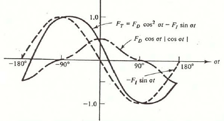
A clear illustration of this second root can be seen by examining Figure 4[1]. Because of the change in form of cos2 σt at σt=-π/2, if FI>2FD, the inertia force term decreases with increasing σt more rapidly than the term with cos2 σt increases. Therefore, the maximum total force is pure inertia.
There is a need to verify that the cause of the second root is because of the quadratic drag term. For example, if the drag force component were linear,
| (7) |
then there is only one root and the maximum total force is always given by
| (8) |
For each floater size, the wave force was calculated as 40.1, 69.3, 164.4, and 554.7 kN, respectively, for 2.5, 3.0, 4.0, and 6.0 m.
3. Results and Discussion
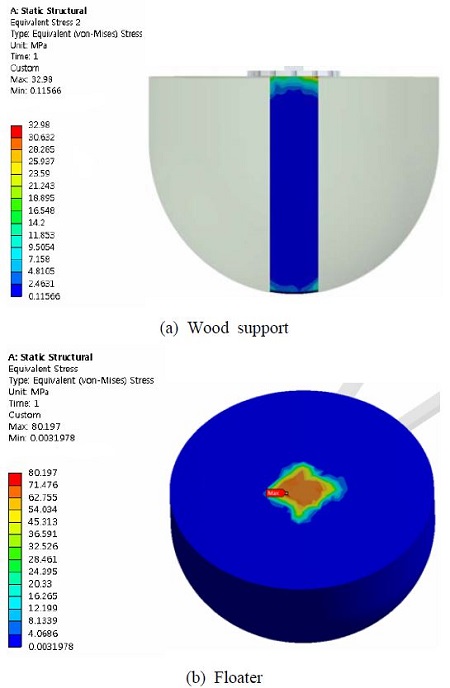
The maximum stress for the scaled model cases showed large stress close to or larger than the yield strength for the FRP and wood materials. For example, the stresses on the floater and wood support are shown for floater size 2.5 m in Figure 5. This is because the external forces for all the new cases are much larger than the miniature model study. By increasing the thickness, the maximum stress distribution was reduced and transferred to the bottom of the floater connecting with the wood support.
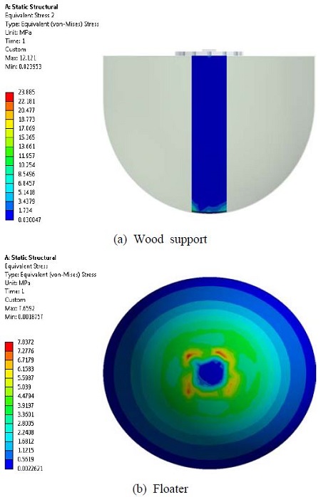
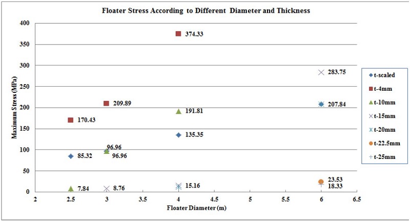
Floater diameter 2.5 m shows at least 10 mm thickness was sufficient to reduce the stresses, as shown in Figure 6. A similar trend was observed for other floater sizes. Floater diameters 3 and 4 m showed that at least 15 mm thickness was needed for a safe design. Floater diameter 6 m showed that at least 22.5 mm thickness was needed for safe application. The maximum stress for all cases has been presented in Figure 7.
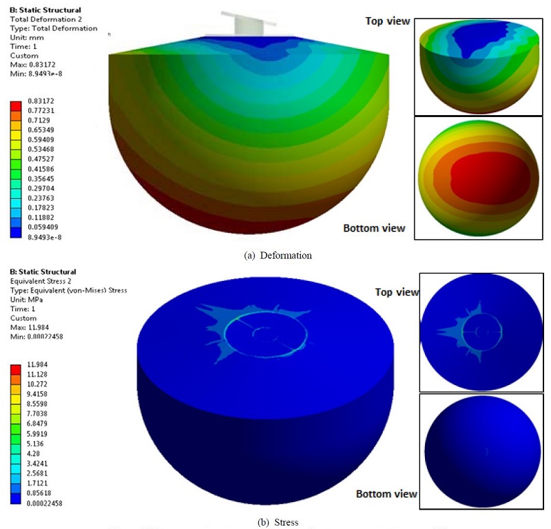
From the four sizes studied, the largest diameter of 6 m was suggested for application to the full scale model. A total of 6 floaters will be sufficient to obtain the rated power. This would also reduce the number of other components on the platform. However, the floater design did not seem to be sufficient due to its large size. The maximum deformation on the 6 m floater was 3.01 mm. Therefore, it was suggested to modify the internal support structures by replacing the wood support and including urethane foam and PVC pipe as shown in Figure 3. This protects the floater from unnecessary corrosion and rotting or erosion. It can also provide sufficient rigid support and reduce the stress and deformation. Figure 8 presents the deformation and stress on the final design of the 6 m floater [2]. A significant drop in deformation was observed from 3.01 to 0.83 mm.
The maximum deformation on the floater was also found to be quite low, less than 1 mm. The smallest stress was also observed on the floater component, with a maximum not reaching more than 12 MPa, which showed a relatively safe design in general.
4. Conclusions
The study concludes with a relatively safe floater design with stresses quite below the yield strength and low deformation. High stress (von-mises) points were found as expected on some initial cases. Modifying the thickness of FRP gave good results for reducing stress and deformation. However, using the first method of scaling will complicate manufacturing costs and increase the time to produce the design because very thick layers of FRP are needed. For the final design, the FRP used was only 9 mm in thickness, but the internal support structure was modified to reduce the total amount of FRP used and also reduce the overall stresses and deformation. For this type of floater, the internal support structures are very important in the design process to reduce material usage and provide a safe design.
Acknowledgments
This work was supported by the New and Renewable Energy of the Korea Institute of Energy Technology Evaluation and Planning (KETEP) grant funded by the Korea government Ministry of Trade, Industry and Energy (No. 2013T100200066).
References
- R. G. Dean, and R. A. Dalrymple, “Water wave mechanics for engineers and scientists”, World Scientific Publishing Co. Pte. Ltd, 2(2), p234-236, (1991).
-
P. M. Singh, Z. Chen, and Y. D. Choi, “Component Structural Analysis on 15kW class Wave Energy Converter”, Journal of the Korean Society of Marine Engineering, 39(8), (2015).
[https://doi.org/10.5916/jkosme.2015.39.8.821]

-
Z. Chen, P. M. Singh, and Y. D. Choi, “Structural Analysis on the Arm and Floater Structure of a Wave Energy Converter”, The KSFM Journal of Fluid Machinery, 18(3), (2015).
[https://doi.org/10.5293/kfma.2015.18.3.005]

- R. E. Prince, “FRP Reinforcements for Structures”, Prince Engineering, online source accessed 21 July 2014, http://www.build-on-prince.com/frp-reinforcement.html#sthash.aB1IQi9j.dpbs.
- Workshop, Wood Density Chart, online source accessed 21 July 2014, https://cedarstripkayak.wordpress.com/lumber-selection/162-2/.
- Vinidex Pty Ltd, PVC Properties, Technical, online source accessed 21 July 2014, http://www.vinidex.com.au/technical/material-properties/pvc-properties/.
- D. W. Green, J. E. Winandy, and D. E. Kretschmann, Mechanical Properties of Wood, Wood Handbook-Wood as an engineering material, Forest Products Laboratory, Madison, USA, (1999).
- ANSYS Inc, “ANSYS Mechanical Documentation”, Ver. 13, (2015).
