A study on rotational motion control for ship steering motion control
Copyright © The Korean Society of Marine Engineering
This is an Open Access article distributed under the terms of the Creative Commons Attribution Non-Commercial License (http://creativecommons.org/licenses/by-nc/3.0), which permits unrestricted non-commercial use, distribution, and reproduction in any medium, provided the original work is properly cited.
Abstract
In general, a series of ship steering motions is composed of a combination of translational motions and rotational motions of the ship. In particular, a series of rotational motions frequently occurs in narrow areas such as ports and canal zones. In this paper, a method was suggested for composing an integrated control algorithm based on the jog dial as a command instrument for rotational motion control. In order to realize the rotational motions, several algorithms were suggested for generating rotational commands, for selecting motion variables, for choosing reference input values for the motion variables, for computing required accelerations and thrusts, and for allocating thrusts to actuators. A simulation program was compiled to execute simulations for three rotational motions. Finally, the effectiveness of the suggested method was verified by analyzing the simulation results.
Keywords:
Ship steering motion, Integrated control algorithm, Rotational motion, Reference input values, Motional variables1. Introduction
The purpose of ship motion control is largely classified into two problems. One is the problem of ship safety against stranding, submersion, and collision occurring during navigation. The other is the problem of accomplishing a given steering command corresponding to navigating a situation accurately.
In order to solve the above problems, much recent research is proceeding to develop control systems for advanced autopilot, track-keeping control that follows a given route in an electronic chart, automatic mooring, dynamic positioning, and so on [1]-[4].
In particular, high-level technologies for ship steering control must be developed as the traffic in a port is busy and as large-scale ships are emerging. An active steering control technology for automatic mooring in narrow ports is a representative example of the systems necessary to catch up with demands [5]-[9].
In order to realize active steering control, implementation of a type of integrated control system is necessary to generate a series of steering motions under the assumption that the considered ship should be fully actuated [10]-[12].
In this paper, an integrated control system based on a joystick and a jog dial with a command instrument is introduced. Joystick commands from an operator are used for translational steering motions, while jog dial commands are used for rotational commands. Control methods for translational motion in an integrated control system for a fully actuated ship have already been proposed in [13]-[15].
Therefore, a control method for rotational motion in an integrated control system is suggested in this paper. Rotational motions of ships include three types of movement: rotation about an imaginary fore axis, rotation about the center of gravity axis, and rotation about an imaginary aft axis. In order to realize these three rotational motions and to execute the corresponding control command, various algorithms necessary to an integrated control system are suggested. As a method for verifying the suggested algorithms, a simulator based on the MATLAB language is composed. Through many simulations covering several command scenarios, the qualitative effectiveness of the suggested algorithms is proved.
2. Integrated control system for rotation
The structure of an integrated control system that is suggested in this paper for ship rotational motion control based on jog dial commands is depicted in Figure 1. The basic structure is very similar to that of the ship translational motion control system suggested in [14].
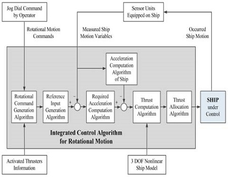
Functional diagram of an integrated control system for ship rotational motion control based on jog dial command
In order for a ship to carry out a desired rotational motion, for example, a rotation about an imaginary fore axis, two thrust forces along two axes and a thrust moment about one axis must be calculated for the given rotational command, under the assumption that the described coordinate system is a body-fixed coordinate system attached to the ship. Then, these forces must be allocated to actuators installed on the ship. All motion variables necessary for control must be measured, fed back, and used to generate a new control command until the given rotational motion command is completely realized. The integrated control system for rotational motion suggested in Figure 1 contains all algorithms required to realize the given rotational motion command.
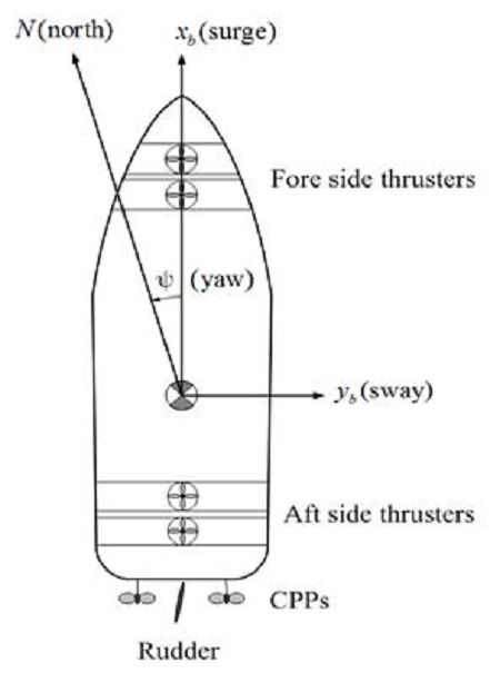
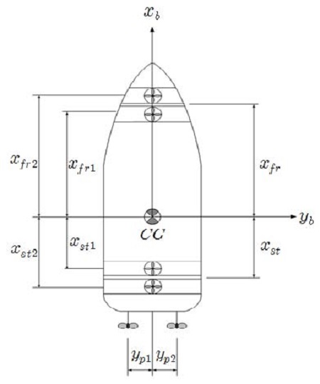
The ship model adopted for the integrated control system is assumed to be as shown in Figure 2, and has two translational motions–one each in the xb axis (surge axis) and the yb axis (sway axis), and one rotational motion, about the zb axis (heave axis), under the body-fixed frame of reference: o-xbybzb. In this case, the origin is assumed to be located at the center of gravity. The ship model is fully actuated to generate all required motions without any constraints. There are two controllable-pitch propellers (CPPs) for propulsion, and two side thrusters in both the fore and aft ends for steering.
In order to achieve the integrated control system shown in Figure 1, the following algorithms are developed. First, it is necessary to develop an algorithm that generates the rotational command given by the operator, and defines the appropriate motion variables corresponding to the command. Next, it is necessary to develop an algorithm that calculates the reference inputs corresponding to the motion variables.
Third, an algorithm to calculate the two required linear accelerations and one angular acceleration is necessary, by comparing the current values of the ship motion variables with reference input values. Fourth, an algorithm to calculate the two required thrust forces and one thrust moment is necessary, by using the required accelerations calculated in the third stage. Lastly, a thrust allocation algorithm is necessary to allocate the required thrust forces and moment to the appropriate actuators.
3. Development of Necessary Algorithms
3.1 Rotation Command, motion variables, and the corresponding reference inputs
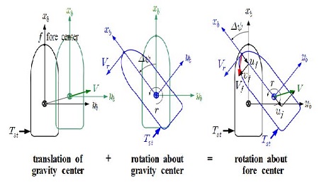
Consider the rotation of the ship about an imaginary rotation axis through an arbitrary point in the fore side. In order to rotate the ship about this axis, only the two stern thrusters are actuated. In this case, as the fore side point through which the rotation axis passes cannot be fixed, the point moves with the surge velocity and sway velocity in view of the body-fixed coordinate frame. This rotational motion mechanism can be explained as the combination of the translational motion of the center of gravity and the rotational motion about the axis passing through the center of gravity [16], as described in Figure 3.
Table 1 describes the variables and coordinates used in Figure 3. Although only the aft side thrusters with Tst are actuated to rotate the ship about the imaginary axis passing through the fore center f, the ship not only moves with a linear velocity V but also rotates about the axis passing through the center of gravity. The rotation causes a tangential velocity Vr of the fore center f.
As a result, the fore center moves with a velocity Vf, where Vf is the vector sum of uf and υf. uf is the xb component of the linear velocity Vf, and is equal to the xb component u of V, because the ship is a rigid body. The yb component of Vf, that is υf, is the vector sum of V and Vr in the direction of yb.
In order that the fore side center f be fixed, the instantaneous linear velocity Vf must be zero. This means that other actuators, such as the CPPs and the fore side thrusters, must be actuated as soon as Vf occurs. From this point of view, the motion variables for command generation and the corresponding reference input values are defined in Table 2. xfr stands for the distance from the center of gravity to the fore center.
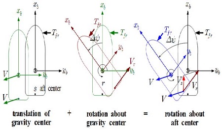
Consider the rotation of the ship about an imaginary rotation axis through an arbitrary point in the aft side. In order to rotate the ship about this axis, at first, only the two fore thrusters are actuated. In this case, as the aft side point through which the rotation axis passes cannot be fixed, the point moves with the surge velocity and the sway velocity.
This rotational motion mechanism can also be explained as the combination of the translational motion of the center of gravity and the rotational motion about the axis passing through the center of gravity caused by the two fore side thrusters, as described in Figure 4.
Table 3 describes the variables and coordinates used in Figure 4. Although only the fore side thrusters with Tfr are actuated to rotate the ship about the imaginary axis passing through the aft center f, the ship not only moves with a linear velocity V but also rotates about the axis passing through the center of gravity. The rotation causes a tangential velocity Vr of the aft center s.
As a result, the fore center moves with a velocity Vs, which is the vector sum of us and υs. us is the xb component of the linear velocity Vs, and is equal to the xb component u of V, because the ship is a rigid body. The yb component of Vs, that is υs, is the vector sum of V and Vr in the direction of yb.
In order that the aft side center s be fixed, the instantaneous linear velocity Vs must be zero. This means that other actuators, such as the CPPs and the aft side thrusters, must be actuated as soon as Vs occurs. From this perspective, the motion variables for command generation and the corresponding reference input values for rotation about the axis passing through the aft center are defined in Table 4. xst represents the distance from the center of gravity to the aft center.
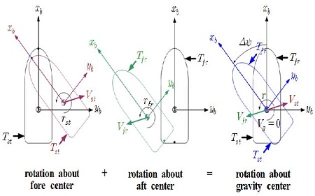
Consider the rotation of the ship about an imaginary rotation axis passing through the center of gravity. In order to rotate the ship about this axis, the two fore thrusters and two aft thrusters must be actuated simultaneously. In the case in which the moment generated by the fore side thrusters is the same as that of the aft side thrusters, the center of gravity does not move, but behaves as if it were fixed.
This rotational motion mechanism can be explained as the combination of the motions of the two cases already discussed. Figure 5 demonstrates the rotational motion mechanism about the rotation axis passing through the center of gravity. Nevertheless, the linear velocity of the center of gravity may not be equal to zero, because the thrust forces by the fore side thrusters and the aft side thrusters are opposite, but their magnitudes are slightly different from each other.
Table 5 describes variables used in Figure 5.
Table 6 represents the motion variables for command generation, as well as the corresponding reference input values, for rotation about the axis passing through the center of gravity, in order for the velocity of the center of gravity to be zero by way of control.
3.2 Computation of required accelerations
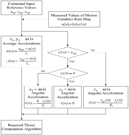
The required linear accelerations in the directions of the xb and yb axes, as well as the required angular acceleration about the zb axis, are computed by comparing the reference values with the current motion values measured at the ship at each sampling time. Although accelerations vary continuously, it is possible to suppose that they are constant during the chosen sampling interval. Under this assumption, algorithms to compute the average accelerations are suggested.
At the current time nTs, it is supposed that the reference velocity in the xb direction is given as uref, and the velocity of the ship in the xb direction is measured as u(n). The average linear acceleration in the xb direction is computed by Equation (1), where Ts is the sampling period:
| (1) |
When the reference velocity in the yb direction is given as υref and the velocity of the ship in the yb direction is measured as υ(n), the average linear acceleration in the yb direction is computed by Equation (2):
| (2) |
From these equations, it is clear that the reference angular velocity and the current angular velocity must be computed prior to computing the angular acceleration. They can be computed using Equation (3) and (4), where ψref is the given reference yaw angle, ψ(n) is the current yaw angle measured at the ship, rref(n) is the computed reference angular velocity, and rs(n) is the computed current angular velocity about the zb axis.
| (3) |
| (4) |
From Equation (3) and (4), the required average angular acceleration about the zb axis is computed by Equation (5):
| (5) |
Equation (5) is used whenever ψ(n) is not equal to ψref at the current sampling time nTs. Incidentally, if ψ(n) is equal to ψref, Equation (6) and (7) are used to compute , whether rs(n) is equal to zero or not.
| (6) |
| (7) |
Figure 6 presents the flowchart of the algorithms for computing the required average linear accelerations in the direction of the xb and yb axes, and for computing the required average angular acceleration about the zb axis.
3.3 Computation of required thrust forces and thrust moment
In order for a ship to acquire the motion commanded by the operator, the required thrust forces in the direction of the xb and yb axes, and the moment about the zb axis must be computed. To do this, the rigid body dynamics for the ship itself, as well as the hydrodynamics of the water surrounding the ship, must be considered. The rigid body dynamics of the main elements to be considered include the inertial forces and moments of the ship. Hydrodynamics from the motion of the surrounding water includes additional inertial forces and moments, added damping forces and moments, restoring forces and moments, etc.
In this paper, the ship motion under consideration is assumed to be a low-speed steering motion, and is thus assumed to be described by nonlinear three degrees-of-freedom differential equations in the surge, sway, and yaw directions. Therefore, the following assumptions are made about the controlled ship and its motion [2][8]:
(1) The considered ship is symmetric with reference to the o-xbzb plane, and the origin of the body-fixed frame is at the center of gravity.
(2) The ship exhibits planar motion in the o-xbyb plane. Thus, restoring forces and moments are neglected from the viewpoint of hydrostatics. In addition, only the three axial motions in the surge, sway, and yaw directions are coupled.
(3) As the ship is under a low-speed steering motion, the second- order nonlinear damping effects due to high-speed motion are neglected.
Under the above assumptions, the equations of motion for the ship are approximately represented as Equation (8) - (10)[14].
| (8) |
| (9) |
| (10) |
where m is the mass of the ship, Iz is the moment of inertia about the zb axis, , and are the added masses and moment, respectively, Yυ, Yr, Yδ, Nυ, Nr and Nδ are the hydrodynamic derivatives, XC, YC are thrust forces exerted by the actuators, and NC is the thrust moment exerted by the actuators.
The reason for describing the equations of motion is to derive recursive equations for computing the required thrust forces and moment so that the control system may generate the rotation command. Therefore, Equation (8) - (10) are rearranged as the recursive Equation (11) - (13) about the thrust forces and moment for XC, YC and NC at sampling time t=(n+1)Ts
| (11) |
| (12) |
| (13) |
where u(n), υ(n) and rs(n) are the current linear and angular velocities, δ(n) is the rudder angle at the current time nTs, , and are the required linear and angular accelerations that must be utilized at nTs in order to satisfy the rotation command, and and are the current linear and angular accelerations of the ship.
Therefore, the required thrust forces and moment at the next sampling time t=(n+1) Ts are obtained from Equation (11) - (13) by using only the previously measured information about the motion of the ship at the current sampling time t=nTs.
3.4 Thrust allocation algorithm
In order to correctly allocate the required forces and moment to the actuators installed on the ship, appropriate and optimal allocation algorithms are suggested.
In this paper, the considered ship is assumed to be the fully actuated ship shown in Figure 7.
Information about the actuator positions installed on the ship shown in Figure 7 is given in Table 7.
The premise conditions and assumptions for allocating the required thrust forces and moments to specific thrusters, so as to accomplish the commanded rotation about the fore center axis, are as follows:
(1) The required thrust force YC(n+1) that is computed to force the linear velocity υf to be equal to zero is allocated to the fore side thrusters and the aft side thrusters at the same time.
(2) The required thrust force XC(n+1) that is computed to cause the linear velocity uf to be equal to zero is allocated only to the CPPs.
(3) Although the required thrust moment NC(n+1) about the zb axis is allocated to the aft side thrusters, it contains the moment generated by the fore side thrusters to produce a υf equal to zero.
Under the above assumptions, all the thrust forces of the actuators are computed by Equation (14) - (19):
| (14) |
| (15) |
| (16) |
| (17) |
| (18) |
| (19) |
The coefficients a1, a2, b1, and b2 are calculated as follows:
The premise conditions and assumptions for allocating the required thrust forces and moments to specific thrusters, so as to accomplish the commanded rotation about the aft center axis, are as follows:
(1) The required thrust force YC(n+1) that is computed to force the linear velocity υs to be equal to zero is allocated to the fore side thrusters and the aft side thrusters at the same time.
(2) The required thrust force XC(n+1) that is computed to cause the linear velocity us to be equal to zero is allocated only to the CPPs.
(3) Although the required thrust moment NC(n+1) about the zb axis is allocated to the fore side thrusters, it contains the moment generated by the aft side thrusters to produce a υs equal to zero.
Under the above assumptions, all the thrust forces of the actuators are computed by Equation (20) - (25):
| (20) |
| (21) |
| (22) |
| (23) |
| (24) |
| (25) |
The coefficients c1, c2, d1, and d2, are calculated as follows:
The premise conditions and assumptions for allocating the required thrust forces and moments to specific thrusters, so as to accomplish the commanded rotation about the axis passing through the center of gravity, are as follows:
(1) The required thrust moment NC(n+1) that is computed to rotate the ship about the axis passing through the axis through the center of gravity, is allocated to the fore side thrusters and the aft side thrusters in the manner in which the coupled moments occur.
(2) The required thrust force XC(n+1) that is computed to force the linear velocity u to be equal to zero is allocated only to the CPPs.
(3) The required thrust force YC(n+1) that is computed to cause the linear velocity υ to be equal to zero is allocated to the fore side thrusters and the aft side thrusters.
Under the above assumptions, all the allocated thrust forces of the actuators are computed by Equation (26) - (31).
| (26) |
| (27) |
| (28) |
| (29) |
| (30) |
| (31) |
The coefficients e1, e2, g1, g2, h1, h2, k1, and k2 are calculated as follows:
4. Simulations and analysis of results
4.1 Specifications of the ship and hydrodynamic derivatives
Several simulations were conducted to verify the effectiveness of the suggested algorithms for the three rotational motions of the ship. The controlled ship model is of the SR-108 container ship [8], which has two side thrusters each at the fore and aft sides, two CPPs, and one rudder. Its specifications are given in Table 8, and the hydrodynamic derivatives used in Equation (11) - (13) are specified in Table 9.
The purpose of this paper is to verify the feasibility of the controlled ship attaining the commanded rotational motion when the suggested algorithms are applied. In this paper, therefore, the actuator dynamic models were neglected, and all actuators immediately and accurately took on the required thrusts. Moreover, the rudder was assumed to be an additional fixed structure, whose action was neglected because the rotational motion was a low-speed steering motion.
4.2 Simulations for performance verification
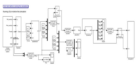
To verify the control performance for rotational motion of the ship, a simulation model was composed based on the MATLAB Simulink software as shown in Figure 8.
In Figure 8, a number of MATLAB functions are shown, such as a function to identify the rotational command given by the operator, a function to generate the rotational command, a function to generate reference inputs, a function to compute the required accelerations, a function to compute the required thrust forces and moment, a function to allocate the thrusts to the actuators, a function to define the ship model, a function to choose the rudder angular position, etc. Detailed explanations of such functions are abbreviated here, but are fully explained in [13].
In order to investigate the behavior of the ship under a rotation command about the axis passing through the fore center, two simulations were carried out by using the simulation program developed in this paper, based on MATLAB’s Simulink.
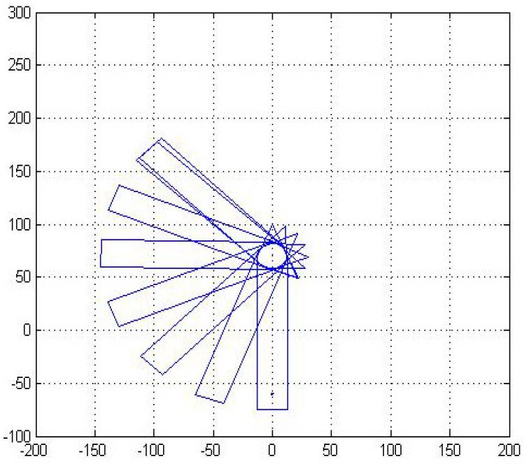
The first simulation was performed to investigate whether the fore center would move or not, by driving only the aft side thrusters with thrust force Tst. The initial yaw angle was ψ(0)=0[°], and the command rotation angle was ψref=135[°].
Figure 9 shows the simulation result of the behavior of the ship. The unit of distance on the horizontal and vertical axes was the meter (m). From the figure, it was known that the fore center (denoted by the red line) moved with linear velocities uf and υf. As a result, the axis passing through the fore center cannot play the role of a fixed hinge point.
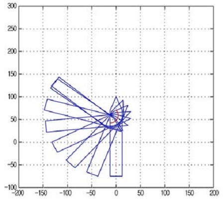
Result of rotational motion in case that only aft side thrusters were actuated with thruster force Tst
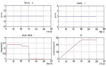
The resultant motion shown in Figure 9 was explained by investigating the motion variables that occurred for the ship during the simulation. Figure 10 demonstrates the motion variables at time nTs, that is, uf(n), υf(n), r(n) and ψ(n).
From Figure 10, it was seen that the velocities uf(n) and υf(n) of the fore center occurred in spite of the rotational command being for the rotation about the axis passing through the fore center.
In order to solve the problem resulting from the first simulation, the integrated control algorithm suggested in this paper was applied to accomplish the rotation about the axis passing through the fore center, in the second simulation. The simulation conditions were the same as for the first simulation.
Figure 11 presents the behavior of the ship for the second simulation, and Figure 12 displays the ship motion variables that occurred in the ship.
It can be seen from Figure 11 that the fore center did not move, but acted as if it were a fixed point. Furthermore, it is seen from Figure 12 that the velocities uf(n) and υf(n) were equal to zero. Therefore, the effectiveness of the suggested control algorithm was proven.
It is important to note that the actuator dynamic models, such as those for the CPPs and the side thrusters, were not considered. From this point of view, the simulation results and the effectiveness of the suggested control algorithm must be analyzed in a qualitative manner.
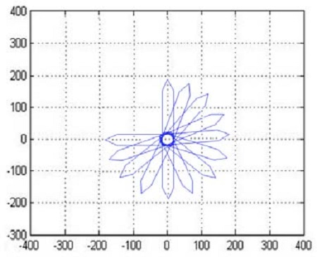
In order to investigate the behavior of the ship under a rotation command about the axis passing through the aft center, another simulation was performed. The initial yaw angle was ψ=0 [°], and the command rotation angle was ψref=270 [°]. The simulation result referred only to the behavior of the ship for the purpose of proving the possibility of qualitative control, as shown in Figure 13.
As was the case for the rotation about the axis through the fore center, the velocities us(n) and υs(n) of the aft center were seen to be equal to zero. This means that the aft center could be considered as an imaginary fixed point.
Therefore, it was convincingly shown that the suggested algorithms for the integrated control system operated well.
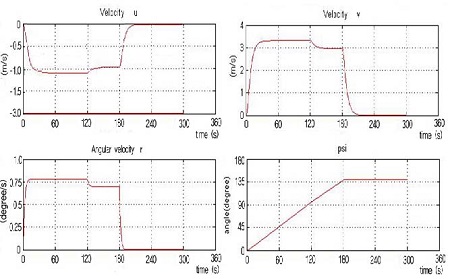
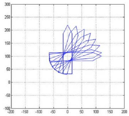
In order to investigate the behavior of the ship under a rotation command about the axis passing through the center of gravity, another simulation was effected. The initial yaw angle was ψ(0)=0 [°], and the command rotation angle was ψref=90 [°]. The simulation result referred only to the behavior of the ship to prove the qualitative possibility of the suggested algorithms. The simulation result, shown in Figure 14, portrayed the behavior of the ship corresponding to the center of gravity rotational command.
As for the two cases described previously, the velocities us(n) and υs(n) of the center of gravity were observed to be equal to zero. This means that the center of gravity could be considered as an imaginary fixed point. Therefore, it was confirmed that the suggested algorithms for the rotation about the axis passing through the center of gravity were qualitatively well suited.
5. Conclusions
In this paper, an integrated control system was suggested for the rotational motion control of a ship under a low-speed steering motion. The controlled ship was assumed to be fully actuated in order for the ship to accomplish three specific types of rotational motion without any constraints. The suggested control system was composed of several algorithms, such as an algorithm to generate rotational commands, an algorithm to define motion variables, an algorithm to generate reference input values, an algorithm to compute the required linear and angular accelerations, an algorithm to compute the required thrust forces and moment, and an algorithm to allocate thrust forces and moment to actuators.
In order to verify the effectiveness of several of the suggested algorithms, various simulations were performed based on a simulation program developed using MATLAB. By means of the simulation results, the integrated control algorithm, including several individual algorithms, was assured of being qualitatively effective.
References
- T. I. Fossen, Recent Development in Ship Control Systems Design, World Superyacht Review, Sterling Publication Limited, Millenium Edition, London, (2000).
- T. I. Fossen, “A survey on nonlinear ship control: From theory to practice”, Proceedings of the 5th IFAC Conference on Maneuvering and Control of Marine Craft, Aalborg, Denmark, (2000).
- M. Breivik, J. P. Strand, and T. I. Fossen, “Guided dynamic positioning for marine surface vessels”, IFAC MCMC'06, Lisbon, Portugal, p20-22, (2006).
- A. M. Lekkas, and T. I. Fossen, Line-of-Sight Guidance for Path Following of Marine Vehicles: Chapter 5, In Advance in Marine Robotics, LAP LAMBERT Academic Publishing, O. Gal Ed, p63-92, ISBN 978-3-659-41689-7 (2013).
- B. K. Lee, Optimal Route Decision and LOS Guidance System, Ph.D. Dissertation, Korea Maritime and Ocean University, Korea, (2005), (in Korean).
- B. K. Lee, and J. H. Kim, “A study on the automatic path tracking control of ship using adaptive fuzzy method”, Proceedings of the 14th Korea Automatic Control Conference, (1999), (in Korean).
- B. K. Lee, J. H. Kim, D. Y. Kim, and T. H. Kim, “A study on the optimal path decision using genetic algorithm”, Proceedings of the 15th Korea Automatic Control Conference, (2000), (in Korean).
- K. H. Sohn, and Y. M. Kim, “A study on mathematical model of manoeuvering motions of twin-screw and twin-rudder ship for construction of real-time ship handling simulator”, Journal of the Korean Society of Marine Environment and Safety, 7(3), p1-16, (2001), (in Korean).
- S. H. Suh, and Y. G. Song, “Study on the control algorithms for the auto-pilot system”, Transaction of the Society of the Naval Architects of Korea, 31(2), p38-44, (1994), (in Korean).
- J. H. Kim, J. K. Lim, and B. H. Choi, “Development of the ship joystick control system”, Research Report Submitted in KTE Co. Ltd, Korea, (2009), (in Korean).
- K. H. Sohn, S. K. Lee, and S. P. Ha, “Mathematical model for dynamics of manta-type unmanned undersea vehicle with six degrees of freedom and characteristics of manoeuvrability response”, Transaction of the Society of the Naval Architects of Korea, 42(4), p399-413, (2006), (in Korean).
- B. K. Lee, and J. H. Kim, “Yaw angle command generation and adaptive fuzzy control for automatic route tracking of ships”, Journal of the Korean Society of Marine Engineering, 25(1), p199-208, (2001), (in Korean).
- J. H. Kim, J. E. Woo, S. H. Park, and J. K. Lim, “Translation control in integrated control system for ship steering motion”, Proceedings of the 38th KOSME Spring Conference, 1, p197, (2014), (in Korean).
-
J. E. Woo, and J. H. Kim, “A study on translational motion control in integrated control system for ship steering motion”, Journal of the Korean Society of Marine Engineering, 39(1), p32-44, (2015), (in Korean).
[https://doi.org/10.5916/jkosme.2015.39.1.32]

-
T. A. Johansen, and T. I. Fossen, “Control allocation – A survey”, Automatica, 49, p1087-1103, (2013).
[https://doi.org/10.1016/j.automatica.2013.01.035]

- J. J. Craig, Introduction to Robotics: Mechanics and Control, Pearson Edition, Prentice-Hall, (2005).

