Prediction of boil-off gas and boil-off rate in cargo tank of NGH carrier
Copyright © The Korean Society of Marine Engineering
This is an Open Access article distributed under the terms of the Creative Commons Attribution Non-Commercial License (http://creativecommons.org/licenses/by-nc/3.0), which permits unrestricted non-commercial use, distribution, and reproduction in any medium, provided the original work is properly cited.
Abstract
Natural gas hydrates are newly emerging as an environment-friendly source of energy to substitute for fossil fuels in the 21stcentury.NGHs are reported to holds much amounts of natural gas (up to 182 standard volumes of gas per volume of hydrate); they are easy to store and safe to carry at about minus 20 degree Celsius under atmospheric pressure because of the self-preservation phenomenon of gas hydrates. The transporting method by gas-ice-hydrate ship carriers has been introduced and developed by a variety of industry and research institutions. Our team has been conducted to develop NGH total systems, including a breakthrough NGH carrier for sea transportation, since 2011. The NGH pellet carrier does not require a separate cooling system for cargo, and the initial temperature is maintained through insulation of the cargo tanks throughout the transport to the final destination. The heat conducted from the exterior and passing through the insulation material of the hull should be cut off as much as possible, but heat inflow inside the cargo tank from an external source is inevitable during transport. In this study, the heat transfer in a cargo tank of a 115K NGH carrier was analyzed through simulation with a commercial CFD code to estimate the boil-off gas/boil-off rate on the developed carrier and understand major hazards that could significantly impact the safety of the vessel.
Keywords:
Natural gas hydrate, Gas carrier, Boil-off gas, Boil-off rate, Risk analysis, Computational fluid dynamic, System design, IMO1. Introduction
Natural gas hydrates (NGHs) are being magnified as an environment- friendly energy source to substitute for fossil fuels. NGHs are a solid phase of natural gas and water that forms a crystalline lattice, and contain natural gas up to 182 standard volumes of gas per volume of hydrate at about minus 20 degree Celsius under atmospheric pressure because of the self-preservation phenomenon. For these reasons, NGH has the advantage of being applicable to small- and medium-sized gas fields that are considered economically infeasible [1]-[4]. Natural gas can be shipped in the liquefied state (LNG), compressed state (CNG), and in the form of hydrates (NGH); the technology is still in the design phase [4].
The technologies of gas hydrate pellet carriers for sea transport has been developed by many industry and research groups. Mitsui Engineering & Shipbuilding Co., Ltd. (MES) has been developed the overall NGH technology such as manufacture of natural gas hydrates from natural gas and water, transportation of the hydrate by ship, and re-gasification of the hydrate to natural gas and water, since 2001. Especially the NGH pellet-type transporting system is known to have the superiority in many aspects, including a high filling ratio in ship cargo tanks, superior fluidity, and improved self-preservation effect. It is one of the best solutions to realizing NGH sea transportation more practical [5]-[8]. The NGH pellet carrier is a major connection in the potential gas hydrate process chain starting with the extraction of natural gas from sources and followed by the production of hydrated pellets and their transportation to onshore storage facilities for further processing or marketing. In 2008, the SUGAR project [9] was carried out in Germany to develop new technologies for the exploration and exploitation of submarine gas hydrate resources and new concepts for the transportation of natural gas from hydrate storage facilities.
Recently, Korean ship building and plant industries have put large amounts of effort in the development of LNG cargo tank technology. Based on the technologies for a LNG carrier, our team has been working on the development of NGH total systems, including a novel NGH carrier, since 2011 [10][11]. In our project to establish thermal analysis technology for NGH cargo tanks, related technologies such as BOG estimation, internal structural material and thickness estimation on insulation have been developed to determine the design and safety level of other ship types with similar scopes, e.g., LNG carriers and crude oil tankers [12]-[15].
In this study, the heat transfer for the cargo tank on 115K NGH carrier was analyzed with a commercial CFD code to estimate the boil-off gas (BOG)/boil-off rate (BOR) on the developed carrier and to understand major hazards that can significantly impact the safety of the vessel. The best knowledge available on alternative technologies for the design and assessment of a cargo tank on an LNG carrier was used; the same analysis and assessment techniques were applied to estimating the BOG/BOR of a cargo tank on an NGH carrier using a commercial CFD code. The reliability of the heat transfer was determined by comparing the results with the data from GTT’s analysis report.
2. Thermal analysis of LNG carrier
2.1 Verification of thermal analysis and reliability using GTT’s data
Table 1 reviews a report on the heat ingress of LNG cargo tanks for preliminary calculations based on GTT’s thermal data for membrane-type LNG carriers. First, we reviewed the data to determine the type and volume of cargo tank to be analyzed and derived the values by calculating the total heat flow rate flowing into the cargo tank. Because shipyards normally select a reliability of less than 3% tolerance for estimating the BOG of an LNG carrier, the same level of reliability was applied.
- (1) Environmental conditions and properties of LNG carrier
- ▪ Environmental conditions:
- - Air temperature: 45 °C
- - Seawater temperature: 32 °C
- ▪ LNG properties:
- - Tank filling ratio: 98%
- - Composition: Pure methane CH4
- - Temperature: -161.5 °C
- - Specific density: 425 kg/m3
- - Latent heat of vaporization: 511 kJ/kg
- (2) BOG calculation
(1)
Here,
- ϕ : sum of all local heat transfers
- ρm : density of methane
- L : vaporization latent heat of methane
- V : cargo capacity (corresponding to 98.0% of total tank capacity)
2.2 Analysis model and boundary conditions
The analysis model for the LNG cargo tank was based on real ship data from the GTT. Because the heat transfer characteristics in the width and longitudinal directions are equal, only one-fourth of the cargo tank volume was modeled in order to reduce the calculation time for grid nodes. The membrane tank was adopted as the thermal analysis model, and the primary/secondary invar and wood for wall insulation were not considered at the wall of the membrane tank. This was so thin because the primary and secondary insulations were made of 0.7 mm invar. The inner wall as modeled using only two-layer insulation because standards organizations have interpreted in rule that it does not have a significant effect on heat ingress from outside the hull. The hull reinforcement of the outer cargo tank was simplified; all external heat effects of the various reinforcements attached to the hull plate were ignored except for some hull structures that can pass well into the cargo tank.
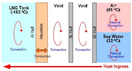
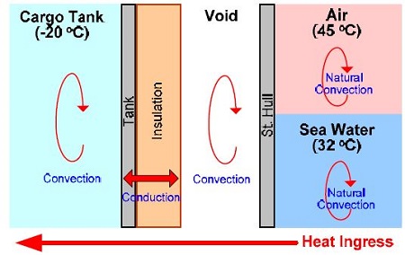
Figure 1 shows the concept for thermal analysis of the hull of an LNG carrier. The process of heat ingress from the air and seawater flows into the inner cargo tank through conduction and convection. The conduction coefficients at each hull part should be determined from the material properties, so the coefficients for conduction in the hull parts and the coefficients of insulation in the insulating materials were formulated according to the properties.
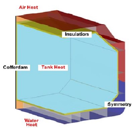
The commercial software ANSYS Fluent ver.14.0 [16] was used for the numerical analysis. The initial temperature conditions were set according to the IGC code (IGC 83/ 90 Amend/ Annex/ Chapter 7/ 7.1.2, Design Temperature) [17] to estimate the BOG of the cargo tank in the LNG carrier. Boundary conditions for all edge parts except the cofferdam were set up under the symmetry condition. Table 2 and Figure 2 present the boundary conditions for thermal analysis of the LNG tank, side/inner void, ballast tank, and insulation according to IGC 83/90.
2.3 Definition of insulation
Because the physical properties of a heat-insulating material used to suppress thermal effects are generally private information, it is difficult to know the characteristics of the insulation installed in the cargo tank on each vessel. In general, insulating materials such as polyurethane foam, perlite, and superlite are applied to the cargo tanks of LNG carriers. In this analysis, the heat-insulating material was given the heat transfer characteristics of perlite of S-shipbuilding.
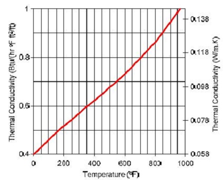
Each insulation has different heat transfer characteristics depending on the temperature variation, like the coefficient of conduction. Therefore, the coefficient of conductivity for this temperature change was considered in the CFD code, and the thermal conductivity was defined as shown in Figure 3.
2.4 Analysis method and results
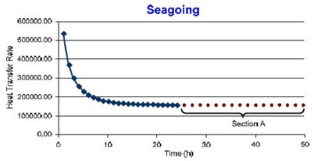
Figure 4 shows the heat transfer rate over time based on transient analysis of the LNG cargo tank. The quantity of the heat flow changed over time. In GTT’s thermal analysis conditions, the BOR was not considered for the loading of LNG or cooling of the cargo tank. Thus, the BOR in our estimation was calculated under thermal equilibrium considering only the operating conditions of the ship. In this study, the thermal equilibrium state was considered to be the average heat flux (25 - 48h) after 24 hours and was used as a factor needed to calculate the BOR (see section A in Figure 4).
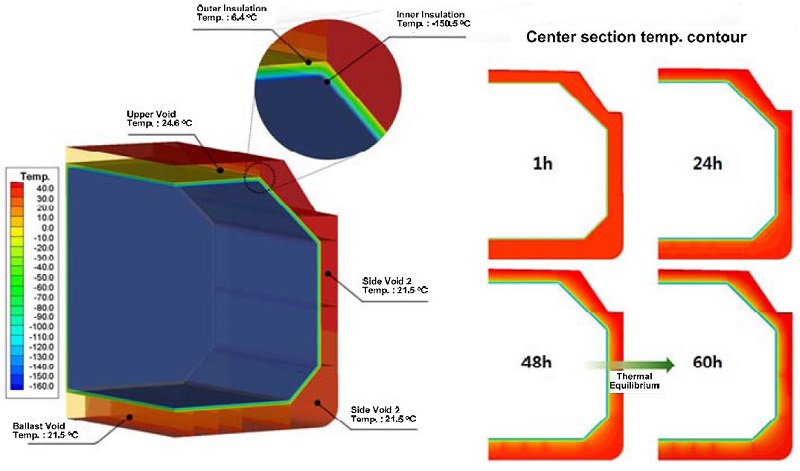
Through a comparison with GTT’s BOR method (see Table 3), the accuracy of the derived prediction model was verified; the maximum relative difference was less than 2% compared with our estimation. Figure 5 (a) and Figure 5 (b) show the temperature distribution of the inner hull structure and the section temperature contours over time. The loading/unloading volumes of the third tank for the LNG ship were calculated as 48,641 (m3) × 0.98. Then, the total ingress calories (φ) for a day was estimated as 152,906(W) × 3,600 (s) × 24 (h).
3. Estimation of BOG/GOR in NGH carrier
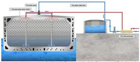
The ship type and design for the transport of the raw material and the equipment of a gas loading terminal depend on the state in which the raw material will be shipped. Figure 6 illustrates an example of the regasification concept for a cargo tank transporting an NGH pellet carrier. Ota et al [5] experimentally confirmed that methane hydrate pellets(MHPs), which are supposed to have similar properties to those of NGH pellet carriers, can be efficiently stowed and transported at around -20 °C under atmospheric pressure because of their self-preservation property.
Based on thermal analysis techniques for the LNG cargo tanks discussed in the previous section, the BOR in the cargo tank of NGH carrier was calculated using the same conditions and methods. Although there is a large difference in temperature for cargo tanks in an LNG carrier (-163 °C) and NGH carrier (-20 °C), the same analysis method for heat transfer with understanding of the model and grid system of an LNG carrier will provided reasonable information and results for an NGH carrier.
3.1 Analysis of heat transfer
NGHs are known to contain large amounts of natural gas (about 160-180 times their volume) and they are easy to store and safe to transport at about -20 °C under atmospheric pressure because of the “self-preservation effect” with the help of insulation. Heat ingress from the outside through the heat-insulating material should be blocked as much as possible, but heat flowing inside the cargo tank from an external heat source is inevitable. We estimated the heat ingress to a cargo tank through heat transfer analysis using the commercial code CFD program Fluent. By calculating the BOG volume based on the CFD analysis, we determined the presence/absence of insulation and its thickness and selected equipment specifications for BOG treatment.
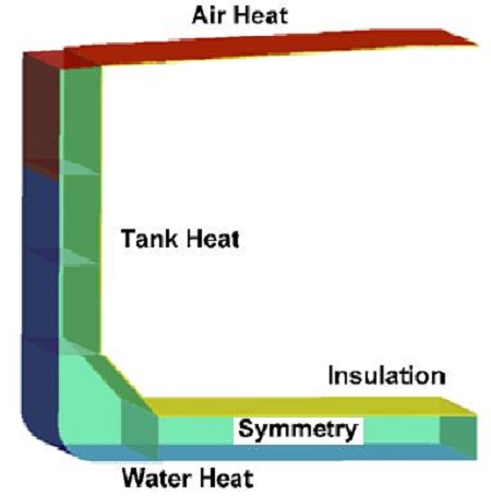
Figure 7 describes the heat transfer mechanism between an external heat source (sea and atmosphere) and the cargo tank of an NGH carrier. The BOG/BOR due to dissociation generated in the cargo tank can be estimated by calculating (a) the heat of the atmosphere and sea flowing into the cargo tank by conduction and convection; (b) the heat ingress inside the cargo tank by the convection of the external heat source, the heat flux of the hull, and the thermal insulating capacity of the insulation; (c) and the amount of heat ingress.
3.2 Definition of analysis model and grid generation
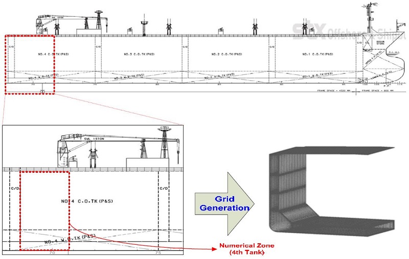
Figure 8 shows the general arrangement and definitions of the model for a 115K NGH carrier. Because the thermal boundary conditions of the longitudinal and transverse direction in the cargo hold are symmetrical, only a quarter of the cargo hold was modeled in this analysis to reduce the computational load. The effects of various reinforcements attached to the hull plate were not considered. Also, the insulating layer, which has complicated geometry in the cargo tank, was ignored because the flow characteristics within the cargo tank were not analyzed.
Although the hull and cargo tank vary slightly in thickness by location, the modeling was carried out using the mean values of the inner and outer hulls for convenience. The thickness of the insulation was set to 100 mm.
3.3 Boundary conditions
The heat sources affecting the BOG in an NGH carrier can be classified as internal heat sources in the cargo tank and external heat sources from the air/sea. Heat transfer takes place by convection in the cargo hold and at the atmosphere/seawater interface and by conduction through the hull and insulating materials. The internal void tank is transferred by convection through the air. Figure 9 and Table 4 present the boundary conditions for each part.
Table 5 presents the thermal conductivity, specific heat, and density for the insulating materials in the cargo tank of NGH carrier based on the temperature variation. Polyurethane foam was used for its material properties; its heat transfer characteristics vary according to the temperature. Thus, in order to consider the coefficient of heat transfer depending on the temperature of the heat-insulating material, the insulation characteristics were considered in the analysis model.
3.4 Results and discussion
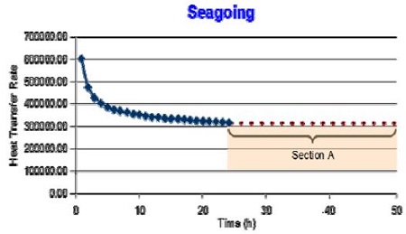
As shown in Figure 10, the heat transfer rate confirmed that the amount of heat flow inside the cargo tank of an NGH carrier varies with time. In order to estimate the total heat flow in the cargo tank, the evaluation method for heat transfer in an LNG carrier was also applied to the NGH cargo tank. We assumed thermal equilibrium conditions and calculated the total heat flow for 24 –48 h (period A) based on the heat flow rate for 24 h. As indicated in Table 6, the BOG and BOR values were estimated using the necessary calories to convert ice in the hydrates and the total amount of gas shipped.
The total heat ingress into the NGH cargo tank over 24 – 48 h was about 2,744,389kJ, and the BOG and BOR based on the amount of heat inflow to the cargo hold were about 1.57 × 10⁵ mol/day and 0.17%/day, respectively. If the BOR is calculated according to the heat flow entering into the cargo tanks under the conditions of atmospheric pressure and ocean temperature using the IGC code of IMO, approximately 0.17% of the total cargo volume would dissociate.
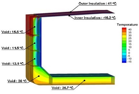
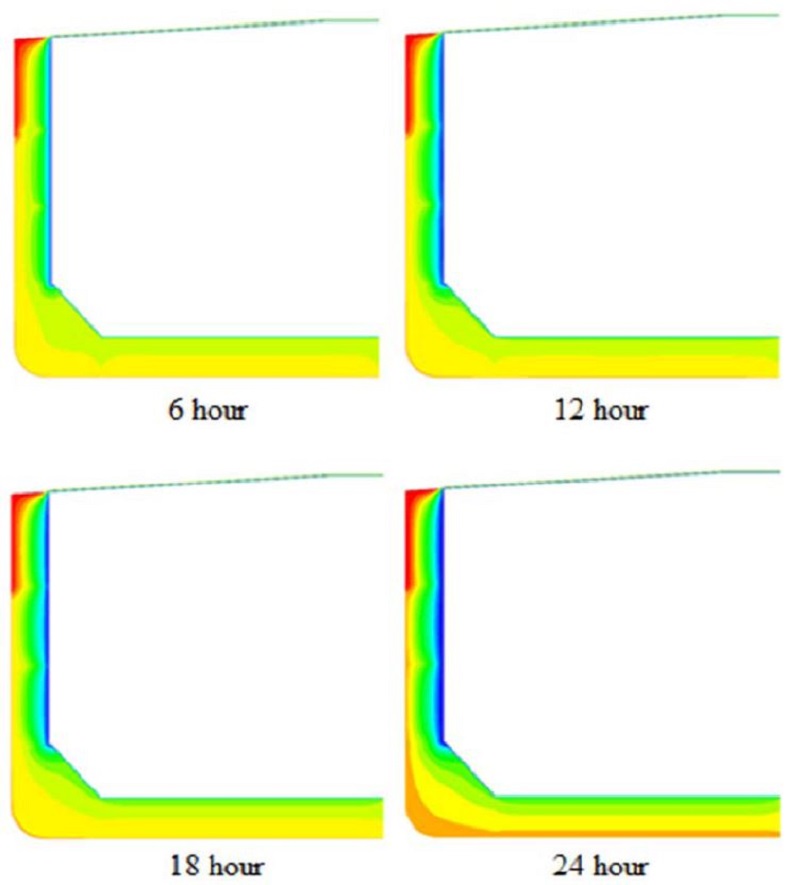
In general, 1.6% of the BOR in hydrates is generated by the self-preservation effect under the environmental conditions at 1 barg and –20 °C. Then the BOR that may occur during ship operation under actual sea conditions was estimated to be 1.77% by summing the dissociation that occurs naturally and caused by an external heat source. Figure 11 and 12 present the temperature distribution in the outer hull and the temperature profile by section in the fourth cargo tank. Heat flowed into the cargo tank over time.
4. Conclusion
The existing thermal analysis method used for LNG carriers and recommendations from the IMO IGC code were used with the atmosphere conditions and ocean temperature to estimate the heat flow entering into the cargo hold of a 115K NGH carrier. In order to verify the reliability of the analysis, we compared the results of our approach with the thermal analysis data in GTT’s assessment report on LNG carriers.
In summary, our results revealed that the total heat ingress into the NGH cargo tank over 24 - 48 h was estimated to be about 2,744,389 kJ, and the BOG and BOR based on this heat flow were about 1.57 × 10⁵ mol/day and 0.17%/day, respectively. Moreover, the BOR including the self-preservation effect was assessed to be about 1.77% during transportation.
Even if this analysis was carried out based on BOG/BOR estimation methods applied to existing LNG cargo tanks, more understanding is required, and processes for a site-specific project based on operating data need to be developed to verify the results of the presented analysis.
Acknowledgments
This study was supported by the Research Fund (Grant No.201300601002) of Korea Maritime and Ocean University“.
References
- J. S. Gudmundsson, and A. Borrehaug, “Frozen hydrate for transport of natural gas”, Proceedings of the 2nd International Conferenceon Natural Gas Hydrates, Toulouse, p415-422, (1996).
- H. Kanda, “Economic study on natural gas transportation with natural gas hydrate (NGH) pellets”, Proceedings of the 23rd World Gas Conference, Amsterdam, (2006).
- T. Nogami, N. Oya, H. Ishida, and H. Matsumoto, “Development of natural gas ocean transportation chain by means of natural gas hydrate (NGH)”, Proceedings of 6th International Conference on Gas Hydrates, (2008).
-
D. C. Lee, R. D. C. Barro, and J. G. Nam, “Synchronization and identification of ship shaft power and speed for energy efficiency design index verification”, Journal of the Korean Society of Marine Engineering, 38(2), p123-132, (2014).
[https://doi.org/10.5916/jkosme.2014.38.2.123]

- S. Ota, H. Uetani, and H. Kawano, “Use of methane hydrate pellets for transportation of natural gas –III – Safety Measures and conceptual design of natural gas hydrate pellet carrier”, Proceedings of 4th International Conference on Gas Hydrates, (2002).
- S. Ota, H. Shirota, T. Nakata, and S. Yuasa, “Development of guidelines for safety of ships carrying natural gas hydrate pellets in bulk”, Proceedings of the 7th International Conference on Gas Hydrates (ICGH 2011), (2011).
-
G. Rehder, R. Eckl, M. Elfgen, A. Falenty, R. Hamann, N. Kaehler, W. F. Kuhs, H. Osterkamp, and C. Windmeier, “Methane hydrate pellet transport using the self-preservation effect: A techno-economic analysis”, Energies 2012, 5, p2499-2523, (2012).
[https://doi.org/10.3390/en5072499]

-
Y. H. Lee, Y. T. Kim, and H. K. Kang, “An analysis on the characteristics of regasification system for LNG-FSRU depending on the changes in performance with vaporization and temperature of the heat source”, Journal of the Korean Society of Marine Engineering, 38(6), p625-631, (2014).
[https://doi.org/10.5916/jkosme.2014.38.6.625]

- SUGAR, (2008), http://ifm-geomar.de/ Accessed October 20, 2010.
-
K. Kim, Y. Kim, and H. Kang, “Recent Advances in Natural Gas Hydrate Carriers for Gas Transportation –A Review and Conceptual Design”, Journal of the Korean Society of Marine Engineering, 38(5), p589-601, (2014).
[https://doi.org/10.5916/jkosme.2014.38.5.589]

-
K. Kim, H. Kang, and Y. Kim, “Risk assessment for natural gas hydrate carriers: A hazard identification (HAZID) study”, Energies 2015, 8, p3142-3164, (2015).
[https://doi.org/10.3390/en8043142]

- IMO, MSC 83/INF.3, “FSA - Liquefied Natural Gas (LNG) carriers details of the formal safety assessment”, (2007).
- IMO, MEPC 58/INF.2, “FSA –Crude oil tankers. London”, (2008).
-
S. B. Park, M. J. Sim, M. S. Kim, J. H. Kim, and J. M. Lee, “A study of thermo-mechanical analysis for the design of high pressure piping system for natural gas fuel vessel”, Journal of the Korean Society of Marine Engineering, 39(4), p425-431, (2015).
[https://doi.org/10.5916/jkosme.2015.39.4.425]

-
G. B. Lee, J. H. Jang, S. K. Lyu, and J. Y. Yu, “Electric power system design and analysis for FLNG vessel”, Journal of the Korean Society of Marine Engineering, 38(5), p573-580, (2014).
[https://doi.org/10.5916/jkosme.2014.38.5.573]

- FLUENT 14.0. Manual 2011, User’s guide –Chapter 13 Modeling heat transfer, p13.
- IMO, IGC 83/90 Amend/annex/Chapter 7/7.1.2, Design temperature.


