Component structural analysis on 15kW class wave energy converter
Copyright ⓒ The Korean Society of Marine Engineering
This is an Open Access article distributed under the terms of the Creative Commons Attribution Non-Commercial License (http://creativecommons.org/licenses/by-nc/3.0), which permits unrestricted non-commercial use, distribution, and reproduction in any medium, provided the original work is properly cited.
Abstract
This study concentrates on a wave energy converter with floaters that extracts the ocean’s energy by moving up and down with the wave motion. The floater is connected to an arm structure, including a hydraulic cylinder that drives a hydraulic generator. This study focuses on a structural analysis of the floater unit, including arm and cylinder components, platform and jack-up system, along with spud columns. Previous studies have been conducted for miniature models for experimentation, but this study focuses on the full-scale model structural analysis. Static structural analysis is conducted using fine numerical grids. Due to the complexity of the whole model, it is analyzed in separate pieces. The floater unit, with arm and cylinder, are combined into one system. The platform is analyzed separately as a single system. There are four jack-up systems for each spud column; only one jack-up system is analyzed, as uniform loads are assumed on each system. There are several load cases for each system, all of which are analyzed thoroughly for stress (von Mises, shear, and normal) and deformation. Acceptable results were obtained for most of the components; unsafe components were re-designed.
Keywords:
Wave energy converter, Component, Stress, Deformation, Structure analysis1. Introduction
One of the major engineering challenges of the 21st century is to meet the drastically increasing demand for energy. This not only applies to Korea, but also as a global problem for nearly all developed countries. Fur-ther increase is caused by the majority of the population living or migrating closer and closer to coastal areas [1]. However, not much has been done to make use of coastal energy. Drew et al. emphasized the advantage of the natural seasonal variability of wave energy, which follows the electricity demand distribution over the course of the year [2]. It is a well-established fact that wave energy has great potential for becoming a major contributor to the worlds increasing demand for renew-able energy solutions [3]-[6].
This study focused on ocean wave energy extraction by implementation of several floaters that follow the wave motion to extract energy and convert it into electricity via a hydraulic generator. Sufficient care has to be taken in its structural design. In particular, the main components of the platform, spud columns, jack-up system, and floater unit with floater, arm, hinges, and hydraulic cylinder need to be well designed.
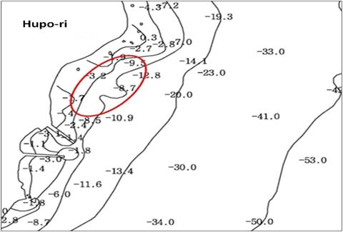
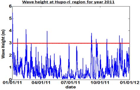
Figure 1 shows the selected test site for the wave energy converter, and depicts the water depth in this region. The Hupo-ri region has a depth of 10-15 m. In addition, Figure 2 presents the available wave height for this site for the year 2011. From this data, it is observed that the maximum wave heights are about 3.5 m, and wave heights close to 1 m, which is very suitable for this type of application, occur frequently.
2. WEC Model and Numerical Method
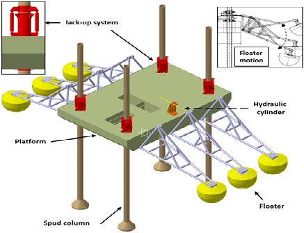
The full-scale model consists of six floater units, as shown in Figure 3. The magnified view on the top left shows a side view of the jack-up system, and the magnified view on the top right details the floater motion. The platform is locked to its four spud columns and can be adjusted using a jack-up system. The dimensions of the platform are 15 m × 10 m × 2 m, and it consists of airtight sections to keep the platform afloat during installation and maintenance. The platform weighs about 100,000 kg, with added loads of control rooms and other components. The clearance height from sea level is 3 m. The spud columns are 25 m long and the wave energy converter is estimated to be deployed at a maximum sea depth of 15-20 m. For clarity, only one cylinder connection is shown.
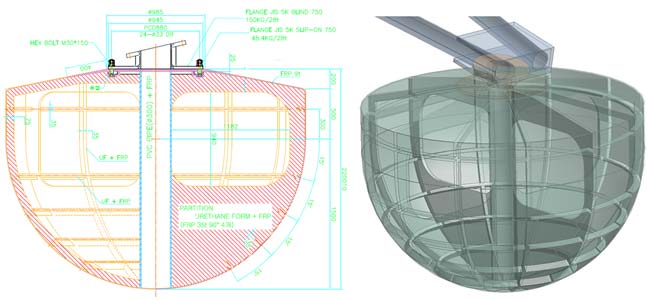
The arm connects to the platform through revolving joints via a hinge system that also includes upper and lower stoppers that prevent the arm from crashing into the platform. The top connector is joined to the cylinder through revolving joints. The cylinder connects to the stand support via a revolving joint. All the connections are made via pins, bolts, and nuts. Permanent joints are connected via welding. The arm connects to the floater by the use of bolts and a steel flange, as shown in Figure 4. The floater is made of urethane foam and fiber-reinforced plastic (FRP) with a 0.3 m diameter polyvinyl chloride cylinder in the center providing added support.
Most of the structure has been constructed from several types of steel, as well as some fiber-reinforced plastic. Table 1 describes the materials used in this study, along with their properties. This study only attempts to conduct structural analysis of the main components by the use of static structure analysis methods. ANSYS Mechanical commercial software [7] is utilized to conduct the structure analysis of the whole system.
The platform component was analyzed separately by fixing the connection to the jack-up system surface. A uniform load of 1,750 kg/m2 was provided. The platform was numerically meshed with tetrahedral meshing consisting of a total of 3.8×10⁶ nodes, and all high-stress regions and edges were further refined. The dead load of the platform alone is approximately 42,000 kg; it is made of structural steel SS400. To determine a safe design, the normal, shear, and von Mises stresses were compared with the permissible stress and yield stress. Gravitational acceleration was also included in all calculations.
Assuming that all loads are distributed evenly, only one jack-up system analysis and one spud column analysis is necessary to determine a safe design. Since there are four jack-up systems and four spud columns, one quarter of the total load is applied to the analysis that includes the platform and six floater units, each consisting of floater, arm, and hydraulic cylinder. The jack-up system and spud column were numerically meshed in a similar way to the platform with 2.4×10⁵ nodes and 5.9×10⁵ nodes, respectively. In a similar way, only a single floater unit was analyzed by applying the maximum wave heave and surge loads acting on a single floater. The floater unit was numerically meshed with tetrahedral meshing, consisting of a total of 8.5×10⁵ nodes. In addition, all high-stress regions and edges were further refined. All contact points for each component connection to the next were given fixed condition for separate analysis. The locking pins in the jack-up system are considered an important component for deeper consideration of deformation and stresses. In each jack-up system, there are a total of four locking pins: two on the upper section and two on the lower section, which are used alternately during the up and down motion of the platform, when needed for height adjustment, or maintenance and installation.
3. Results and Discussion
3.1 Platform Analysis
Table 2 compares the normal, shear, and von Mises stresses on the platform. The criteria used for permissible stress are: normal stress is 0.8 times of yield strength, and shear stress is 0.53 times of yield strength. Results show that the normal and shear stresses are below the permissible stress. The equivalent von Mises stresses are also below the yield strength. The distribution of deformation on the platform is presented in Figure 5 (left). Regions of large deformation are circled in the figure. A maximum deformation of 0.0016 mm was found, which is quite small considering the full size of the plat-form. The von Mises stresses are shown in Figure 5 (right), with maximum points marked by the four circles. Overall, the stresses are shown to be below 20 MPa, except for the maximum points shown in Table 2. It can be inferred from these results that the overall platform design is within a safe margin.
3.2 Jack-up System Analysis
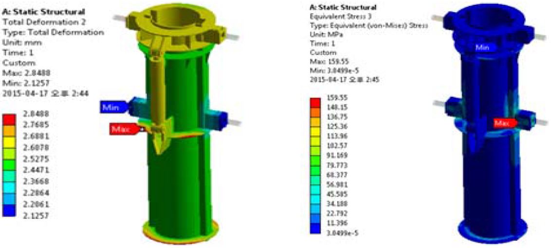
The jack-up system results are presented in three parts. The first part, illustrated in Figure 6, shows the overall distribution of deformation and stress on the entire structure. A maximum deformation of 2.8 mm was observed at the connecting points to the platform, while about 2 mm of deformation was observed on the top section of the jack-up system, including the two hydraulic cylinders. Stresses on these areas were quite low, less than 20 MPa. However, larger stresses were observed at the joints of the locking cylinder, with a maximum of 159 MPa.
The second part, seen in Figure 7, shows more detailed results for the distribution of deformation and stresses on the locking cylinder. The maximum deformation of 2.8 mm was observed at the connector between the pin and the locking cylinder. The locking cylinder is fixed to the jack-up system by four bolts. There is a small clearance of 2.5 mm allocated for the pin to slot into the hole. This clearance also contributes to the bending of the connector, hence contributing to the large stress observed on the end points of the connector. It is suggested that using a more ductile material for this connector part would be advantageous.
The third part also shows a more detailed view of the distribution of deformation and stress on the pin (see Figure 8). The pin experienced a maximum deformation of 0.037 mm and a maximum stress of 115 MPa. It can be inferred from these results that the pin was designed to a safe margin.
3.3 Spud Column Analysis
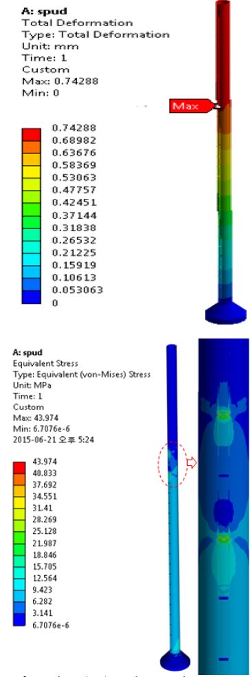
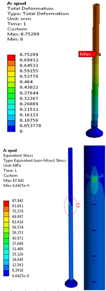
The spud column, made of 17.5 mm thick steel pipe with an outside diameter of 609.6 mm and a total length of 25 m, consists of welded plates 35 mm thick on both sides for connecting with the locking pins. The plates are welded with a pitch of 800 mm in between, with a total of 26 plates on each side. The bottom of the spud column is joined to a lower base to provide stable support to the structure. The base acts as an on-surface foundation so that it is easy to pull up during relocation or maintenance work.
Two types of structural analysis were conducted on the spud column. The first analysis was conducted by assuming all four pins were locked, while only two pins were locked while the second analysis was conducted. The difference in stress was twofold, while the deformation remained the same, as shown in Figures 9 and 10. A maximum deformation of 0.75 mm was observed at the upper section, and maximum stress was found on the welded plates as 44 and 88 MPa for two pins and four pins, respectively. Overall, the structure can be considered safe, as it does not exceed the yield stresses and experiences a very low deformation.
3.4 Floater Unit Analysis
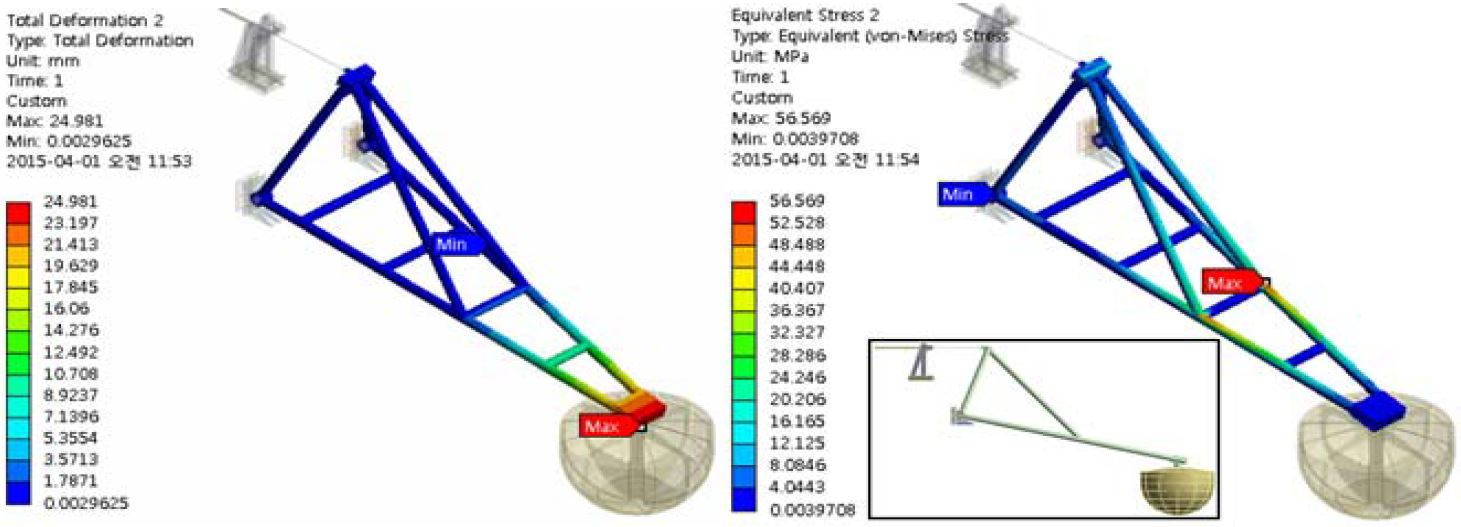
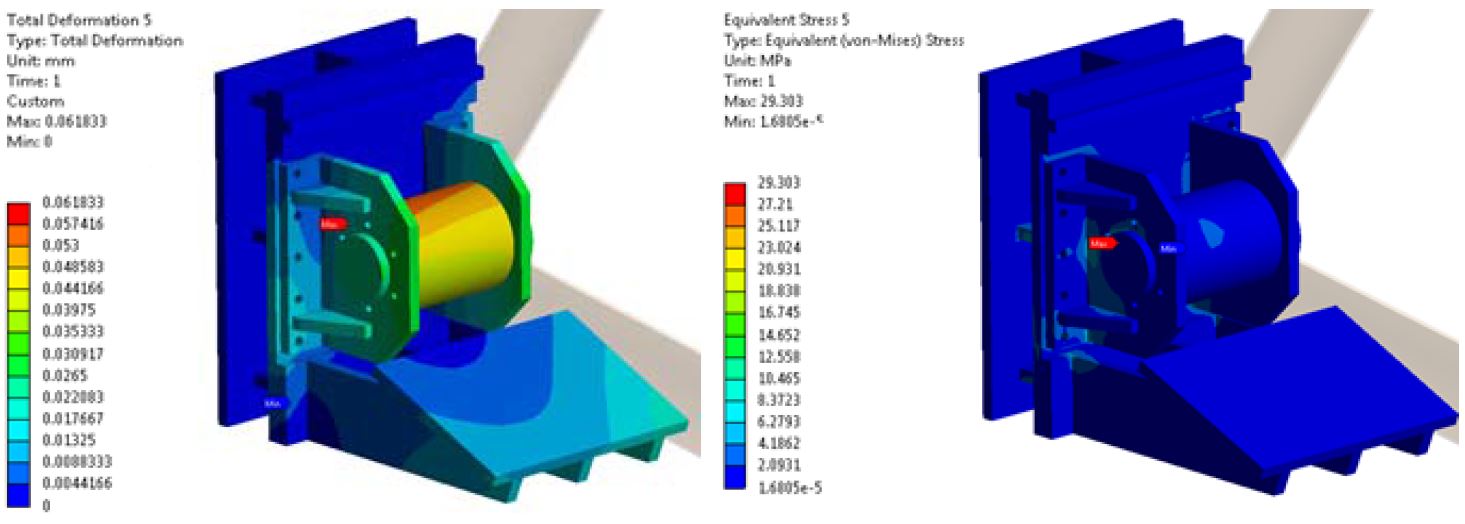
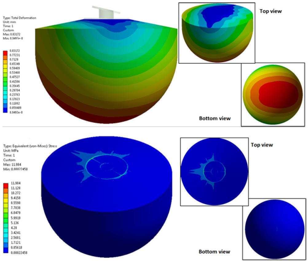
The floater unit mainly comprises four parts: the arm, the hydraulic cylinder, the hinges, and the floater. Figures 11 to 14 show the maximum deformation and stress on a single floater unit. The arm experiences a 25 mm deformation at the tip connecting to the floater, which is quite small considering the total length of the arm is about 9 m. Stress levels are also generally observed to be less than 10 MPa, with a maximum of 56.6 MPa occurring at the support joints near the mid-section. The hydraulic cylinder was found to experience the maximum deformation (33 mm) and stress (120 MPa) of all the floater unit components. The hinges shown in Figure 12 presented quite a low deformation of 0.06 mm, as well as a low stress of 29.3 MPa. However, it is assumed that this part may show a larger stress if a dynamic analysis is conducted, especially on the stopper components. The maximum deformation on the floater was also found to be quite low–less than 1 mm. The smallest stress was also observed on the floater component, with a maximum not reaching more than 12 MPa, showing a relatively safe design in general.
4. Conclusions
This study caused us to conclude that the current platform is a relatively safe design, with both stresses below the permissible stress and low deformation. High-stress (von Mises) points were found, as expected, on some connecting locations of internal beams in the platform; nevertheless, these points are below the yield strength of steel. The locking cylinder in the jack-up system seems to experience the maximum stress level, and the hydraulic cylinder in the floater unit also shows relatively high levels of stress. The other components showed quite low levels of deformation and stresses in general. However, a more detailed observation needs to be carried out during the actual operation of the test facility. Under these conditions, perhaps modifications would be needed, if weaker components of the design were thus identified. These additional observations are needed because consideration must be given to the harsh environments expected in offshore conditions, which cannot be completely replicated with simulation.
Acknowledgments
This work was supported by the New and Renewable Energy of the Korea Institute of Energy Technology Evaluation and Planning (KETEP) grant funded by the Korea government Ministry of Trade, Industry and Energy (No. 2013T100200066).
References
- L. Creel, “Ripple effects: Population and coastal regions”, Population Reference Bureau, 12(4), p500, (2003).
-
B. Drew, “A review of wave-energy converter technology”, Journal of Power and Energy, 223, (2009).
[https://doi.org/10.1243/09576509JPE782]

- A. B. Melo, “Ocean energy - state of the art”, Wave Energy Centre, (2009).
- J. P. Koefoed, P. Frigaard, and M. Kramer, “Recent developments of wave energy utilization in Denmark”, Proceedings of the Workshop on Renewable Ocean Energy Utilization at 20th Annual Conference, Korean Society of Ocean Engineers, (2006).
-
J. S. Oh, T. Komatsu, and Y. H. Kim, “Theoretical analysis of wave energy converter”, Journal of the Korean Society of Marine Engineering, 32(1), p169-174, (2008).
[https://doi.org/10.5916/jkosme.2008.32.1.169]

-
K. Hadano, S. B. Lee, and B. Y. Moon, “Dynamics model of the float-type wave energy converter considering tension force of the float cable”, Journal of the Korean Society of Marine Engineering, 38(2), p217-224, (2014).
[https://doi.org/10.5916/jkosme.2014.38.2.217]

- ANSYS Inc, “ANSYS Mechanical Documentation”, Ver. 13, http://www.ansys.com, Accessed November 10, 2013.

