
Shore power to ships and offshore plants with flywheel energy storage system
This paper describes a study of major shipyard’s electrical network and simulation of applying flywheel energy storage system on the electrical network at shipyard for shore-power to ships and offshore plants in order to save fuel consumption on engines, mitigate voltage sags, and prevent blackout due to pulsed load and fault, resulting in reduction of air emission into atmosphere. The proposed energy recycling method with FESS (Flywheel Energy Storage System) can be applied for electrical power system design of heavy cranes at shipyards.
Keywords:
Shore power, Offshore plant, Electrical distribution, FESS (Flywheel Energy Storage System)1. Introduction
Major shipyards in Korea have been suffered from voltage dip whenever big motor starting onboard ships and plants berthed at a quay and experience black out resulted from the circuit breaker tripping by under voltage protection relay. There are several step procedures to be checked before starting heavy consumers. One has to contact an operator who is responsible for monitoring voltage drop along the electrical distribution at mid transmitting stations if the big motor is possible to start to prepare the official test. If not possible, they have to start an electrical generator in vessels, meaning it is needed to change the shore-power to ship electrical power in order to reserve spinning energy enough to ride through upon connecting big transformers or starting motors. It is noted that a generator is running at low load after the inrush current is back to normal state and the motor has been passed through starting period, which is necessary to improve with advanced technologies. So, we propose a sort of energy storage system that can mitigate voltage drop and supply stable power to ship auxiliaries. This study limits the scope to those that are most efficient and applicable to distribution parts of electrical network at shipyard although many varieties of energy storage technologies are available today. The three technologies that qualify for practical use in power network: batteries, flywheel, and ultra-capacitors.
FESS is given priority as a economic and efficient system applicable for shipyards.
A fly is a heavy wheel that maintains the kinetic energy in the system when rotating. When the AC input power fails and energy is extracted from the system the fly energy storage system operates as an AC generator (Via DC to AC inverter) and uses kinetic energy of the flywheel to supply the output voltage. Storage of kinetic energy in rotating mechanical systems is attractive where rapid absorption and fast release of stored energy is critical. Highly developed FESS systems have rotors that are made of high strength carbon materials, which are suspended by super conducting magnetic bearings in a vacuum housings. It can be spinning at speeds from 10,000 to 50,000 rpm and it will take few minutes to reach to rated speed which is much faster than other forms of energy storage systems.
The conventional power system of shipyard is modeled and with FESS to verify the stability of designed power system. Electrical service reliability has been analysed and discussed using MATLAB SIMULINK.
2. Arrangement of the electrical distribution system at shipyard.
At shipyards the typical distribution system consists of sub-transmission circuits with voltage rating 6.6kV and 154kV which deliver energy to the distribution substation, which converts energy to a lower primary system voltage for local distribution, primary circuits or feeder, usually operating in the range of 4.16 to 34.5kV and supplying load in well defined geographic area, and Secondary distribution with distribution transformers convert electrical energy from primary voltage to utilization voltages (220 to 690V). Shore power system to ships and plants is meant that the connection of supply cable from shore is carried out by terminals in shore connection boxes to a receiving switchboard when power supply is from shore side for ship power at quay. Interlocking system is so arranged that the connection to shore can not be fed from the vessel’s generators.
As shown in Figure 1, at stage of new building ships and plants, most of berthed ships and plants are supplied from shoreside power at voltage level 440V and 11kV distribution boards at quay at shipyard because they have 3 to 8 generators in engine room at voltage of 450V, 6.6kV, and 11kV. An on-board shore-power system consists of receptacle panels, voltage switching board, circuit breakers, and control and monitoring system. Depending on the frequency and voltage of a shore-power supply and a ship's electrical system, a second transformer to bring voltage further down from the shore-side power system and/or an electrical frequency (i.e., 50 Hz vs. 60 Hz)converter may be needed. Power switching over can be performed either by manually switching from on-board power to shore-power, or it can be achieved by a computerized, automatic synchroniza- tion and power transfer system. Power consumption for building ships and offshore plants at one of major shipyards in Korea was recorded as 127,127 MWh per year during 2012.

Typical layout of Shore-power to ships
On the other hand, effective air emission can be obtained thanks to using shore-power. Using the Port of Los Angeles 2005 port-wide auxiliary engine emissions for all ships and air emission reductions by shore-power are almost no air emissions when a vessel uses shore-power. About 95% of hotelling time uses shore-power, therefore, 95% reduction efficiency for all air pollutants is achieved. It is evident that significant emission reduction of all three air pollutants (NOx, SO2 and PM) can only be achieved by using shore-power as shown in Table 1.

Comparison of emission reduction of using shore-power to several vessel types at the port of Los-Angeles
This shore-powers provides an effective, convenient solution to the problem of emissions to the atmosphere. However, problematic area where we note is that the shore-power is limited to certain capacity due to severe voltage drop in case that heavy consumers like ballast, lubrication, inert gas fans, electric cargo pumps, seawater pumps, and cranes are needed to start for system testing. An operator normally puts an electrical generator in operation resulting he shall change the shore power to ship electrical power to reserve spinning enough to ride through upon connecting big transformers or starting motors. It is observed that generator is running at low load after the inrush current and the motor starting period, which is necessary to improve with advanced technologies.
3. Proposed SPDS(Shore-Power Distribution System)
3.1 Flywheel Energy Storage Systems
The FESS consists of a high-inertia composite rotor suspended by magnetic bearings in a vacuum housings. A motor is supported on the shaft. The motor is driven with a variable voltage, variable frequency DC-to-AC inverter. While a battery stores energy chemically, FESS stores energy in rotational kinetic form in mechanical systems. Current is delivered to the motor to charge the flywheel, which spins up the rotor. When the rotor reaches full speed, it is meant fully charged. The motor acts as a generator and is driven by the kinetic energy stored in the rotor to discharge when necessary. In addition to the mechanical flywheel systems other power electronics are required to control the power input and output, speed, frequency etc. The kinetic energy stored in a flywheel is proportional to the mass and to the square of its rotational speed according to Equation (1)
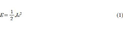
where E is kinetic energy stored in the flywheel, J is moment of inertia and ω is the angular velocity of the flywheel. The moment of inertia for any object is a function of its shape and mass. For steel rotors the dominant shape is a solid cylinder giving the following expression for a J.
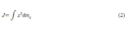
where x is the distance of the differential mass from the axis of rotation. In the case of a flywheel where the mass m is concentrated in the rim at radius r, then the moment of inertia is given by:
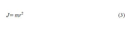
Substituting equation (3) in (1) gives:
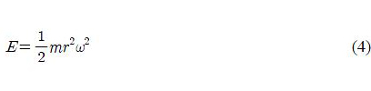
which shows that high angular velocity is more important than mass to achieve high stored energy[1].
The FESS storage capacity of proposed power plant needs a total of 30 MJ of delivered energy based on 1 MW of power for 30 seconds discharging duration. It is enough stored energy for mitigating voltage drop during starting big motors and due to inrush current of transformers less than 1MW.
3.2 SPDS with FESS
Shoreside connection panels are located near quays which cables are layed under ground at about 1 to 10km distance from mid sub transformers. Shore-power voltage is measured at 410 to 430V in front of switchboard at stationary operation. Transient voltage variation is recorded below 370V in event of starting 200kW motor. It has been noted that several black outs took place in ship whose power is supplied by shore-power during clearing faults by protection relays of circuit breakers in case there is a fault like short circuit or earth on other distribution lines. FESS is a good system to reduce voltage sag and to continue supplying power to consumers in mean time when the fault is cleared by the circuit breaker. Figure 2 shows grid power is transmitted to substations inshipyard and distributed and converted through transformers to voltage of ship power. It is used for FESS to be charged in normal mode and to be discharged in event that voltage of EDS is lowenough to trigger the FESS to discharge and the ESD is under fault. Shipyards in Korea can save fuel(diesel oil) proportion to electrical power which is muchcheaper than diesel oil by using shore-power. Estimated total electrical power from ship generators in Korea is about 61,792MW per year that is almost half total electrical power consumption at one of major shipyards as shown in Table 2.

SPDS with FESS
Estimated power consumption to several ship types at ship yards in Korea due to ship generators in operation per year
4. Simulation Result
Two simulated cases are performed in order to compare each other if the simulation result of proposed power system can improve the power quality such as voltage and frequency variation that can be the same as transient state of motor RPM. The first simulation is undertaken with shipyard grid online without FESS and 2.250HP motor is put for starting and running as shown in Figure 3.

Shore-power without FESS model
The second simulation is made with shipyard grid online with FESS and 2.250HP motor is put for starting and running as illustrated in Figure 4. The transient variation of bus voltage, motor rpm, and current are monitored. Figure 5(a) illustrates bus voltage is down below 0.85(pu) without FESS, which exceeds 15% of rated voltage and Figure 5(b) shows voltage dropped about 4% of rated voltage with FESS. Figure 6(a) shows motor rpm is down around 1730rpm and Figure 6(b) indicates motor rpm is dropped about 1760rpm, meaning motor rpm is the same nature of bus frequency supplied from sources. Frequency of power supply with FESS is improved compared with Shore-power without FESS. Figure 7 (a)and (b) illustrate motor current is increased at initial period and decreased when the load is connected. Figure 7(a) shows when the circuit breaker of motor was on starting current jumped up at around 0.05 seconds and was reached at peak value around 0.07 seconds whereas Figure 7(b) shows current was added immediately by FESS in beginning of motor starting and reduced at minimum around 0.1 seconds.

Shore power with FESS model

Transient variation of bus voltage(a: without FESS, b: with FESS)

Transient variation of motor RPM(a: without FESS, b: with FESS)
5. Conclusion
This paper describes the advantage of FESS on shore-power to ships and offshore plants. Model of SPDS and with FESS were simulated in Matlab for transient voltage, motor rpm, and motor current to evaluate if proposed SPDS has improved power quality. The result obtained from the simulation shows the voltage is deviated by less than 4% and Motor rpm less than 1% within 0.6 second in discharge mode upon starting a big motor. The proposed SPDS can provide reliable power supply to ships and offshore plants for starting heavy consumers like motors or energizing transformers, improve the operability, and prevent blackout resulting in reduction of air emission, maintenance cost. The proposed SPDS can be applied for electrical power system of heavy cranes at shipyards in order to recycle energy. When lowering load the power generated from hoist is charged to FESS. When hoisting load main power and power from FESS are used together.

Transient variation of motor current (a: without FESS, b: with FESS)
Acknowledgments
This work is the outcome of a Manpower Development Program for Marine Energy by the Ministry of Oceans and Fisheries and following are results of a study on the “Leades INdustry-university Cooperation” Project, supported by the Ministry of Education, Science & Technology(MEST)
Notes
References
-
Chul-ho Kim, Yoon-sik Kim, Hyun-woo Jeong, Seung-nam Ryu, and Kyoung-kuk Yoon, “Electric power system design and analysis for drilling rigs”, Journal of the Korean Society of Maritime Engineering, 36(7), p942-947, (2012).
[https://doi.org/10.5916/jkosme.2012.36.7.942]

-
Hyun-Woo Jeong, Yoon-sik Kim, Chul-Ho Kim, Sung-Hwan Choi, and Kyoung-kuk Yoon, “Analysis on application of flywheel energy storage system for offshore plants with dynamic positioning system”, Journal of the Korean Society of Maritime Engineering, 36(7), p935-941, (2012).
[https://doi.org/10.5916/jkosme.2012.36.7.935]
-
Jin-Seok Oh, Sung-Young Jung, Yeong-Kyung Kong, Jae-Goo Bin, and Han-Ho Kim, “Control algorithm development for design of cooling system in high-power propulsion motor”, Journal of the Korean Society of Marine Engineering, 34(1), p195-201, (2010), (in Korean).
[https://doi.org/10.5916/jkosme.2010.34.1.195]
-
Satish Samineni, Brian K. Johnson, Herbert L. Gess, and Joseph D. Law, "Modeling and analysis of a flywheel energy storage system for voltage sag correction", IEEE Transactions on Industry Applications, 42(1), p42-52, (2006).
[https://doi.org/10.1109/TIA.2005.861366]