An obstacle avoidance system of an unmanned aerial vehicle using a laser range finder
Recently, unmanned aircrafts for safe measurement in hazardous locations have been developed. In a method of operation of unmanned aircraft vehicles (UAV), there are two methods of manual control and automatic control. Small UAVs are used for low altitude surveillance flights where unknown obstacles can be encountered. Obstacle avoidance is one of the most challenging tasks which the UAV has to perform with high level of accuracy. In this study, we used a laser range finder as an obstacle detector in automatic navigation of unmanned aircraft to patrol the destination automatically. We proposed a system to avoid obstacles automatically by measuring the angle and distance of the obstacle using the laser range finder.
Keywords:
Unmanned Aircraft Vehicles(UAV), Laser Range Finder(LRF), Obstacle Avoidance System1. Introduction
The Unmanned Aerial Vehicle (UAV) is an emerging technology being adapted for use in a wide range of applications such as remote sensing, scientific research, and search and rescue since it is a unmanned aircraft controlled by radio remote control autonomous flight. Hence, it is suitable for UAVs to operate in disaster areas for monitoring, observing, and gathering needed information for rescue teams [1].
Recently, some necessities of operation safety to prevent collision with humans or other objects have been increased. Many researchers have investigated the use of different types of obstacle detecting sensors, such as ultrasonic, radar, laser, and vision sensors to detect obstacles [2]-[6]. To effectively prevent the operating vehicle from colliding with an obstacle, it is necessary not only to locate the detected obstacle, but also to avoid a collision based on the assessment of the possibility of collision in terms of the relative motion between the vehicle and the detected obstacle.
The research reported here aimed to search for an effective method of obstacle detection and identification for autonomous flight. To accomplish this goal, a laser range finder-based obstacle detection system was studied. Thus, in this research, a laser range finder (LRF) is explored as a means of identifying and characterizing potential obstacles in unknown and hazardous environments. The LRF have some advantages such as longer detecting distance, bigger angles, and free of sun rays and other environments [7][8]. It is used to find the distance and the angle between obstacles. From this information, the UAV can automatically avoid the barrier. Once the UAV detects obstacles and finds safe flight path by LRF, it can navigate safely to a destination.
2. Experimental Apparatus and Method
A UAV is often divided into two categories of fixed-wing aircraft and rotary-wing aircraft. The fixed-wing aircraft is a general plane with fixed wings and its wings are stiffly attached to the craft. The rotary-wing aircraft is similar to a helicopter and the top blade rotates to gain propulsion.
The fixed-wing aircraft has a simple structure. Its maximum speed is fairly high and has advantage of high altitude flight. On the other hand, as the rotary-wing aircraft is able to take off and land vertically, the hovering of the rotary-wing aircraft is possible. And it is easier to control than the fixed-wing aircraft because it is able to move about in all directions. Therefore in this study, we used a quad rotor helicopter (QRH).
2.1 The Assembled UAV
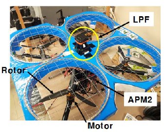
QRH used in this study is shown in Figure 1. The QRH has four rotors of substantially equal diameters located at the four corners of a rectangle. The assembled QRH consists of APM2 controlling panel, which adjusts PID control, and LPF to detect obstacles.
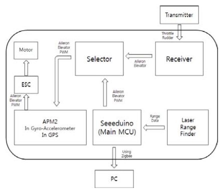
To control the aircraft, we used the transmitter. l By receiving PWM signals of the throttle, roll, pitch, yaw from transmitter, APM2 can be precisely controlled the motor through PID control as shown in Figure 2. APM2 is one of automatic control system using open source and it includes 6-DOF accelerometer, Gyroscope and GPS in one-chip control board.
2.2 Characteristics of LRF
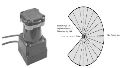
LRF employs a laser optical scanner to detect the distance of an object of interest by measuring the “"time-of-flight”" of laser light pulses. The developed obstacle detection system can horizontally scan a 270° with 0.25° resolution as shown in Figure 3. The maximum distance can be different and can also vary depending on the used devices. But the distance of the device used in this research (UTM-30LX, HOKUYO co.) is up to 30m.
2.3 Configuration of obstacle collision avoidance system
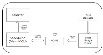
Figure 4 is configuration of obstacle collision avoidance system. When the LRF finds the obstacle, it sends data into Seeeduino (Main MCU). MCU sends PWM signals into the Selector after calculating the direction of avoidance depending on the direction of the observed obstacle.
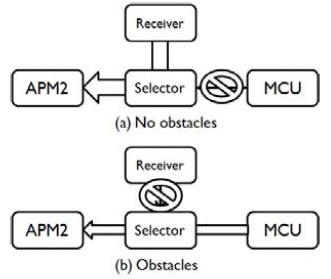
Selector connects APM2 control board with MCU. If obstacles are not detected on flight path, which means a normal state, the selector sends the signal from Receiver to APM2 as Figure 5(a). Conversely, when obstacles are detected, it sends the signal of avoidance from MCU to APM2 as Figure 5(b). This device is to make sure the superimposed PWM signals from Receiver and MCU does not interfere and were sent to APM2 board.
2.4 The algorithm of avoiding system
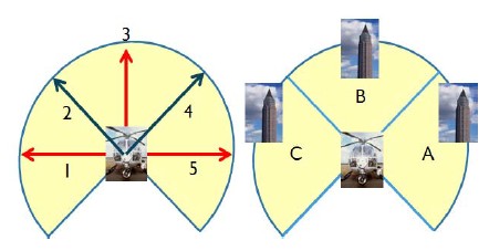
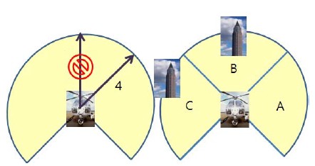
In order for an aircraft to measure the obstacle and automatically avoid, it requires an algorithm that can calculate where the obstacle is and where to avoid it. We established some barrier regions divided into three parts with 270 degrees across flight pass and then each region is 90 degrees. All directions that the aircraft can navigate are separated into five directions such as left-side (1), top-left (2), front (3), top-right (4), right-side (5). in order to provide algorithm for detection and avoidance of barriers. Figure 6 shows proceeding flight directions and barrier regions in which obstacles can be detected.
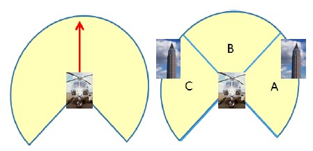
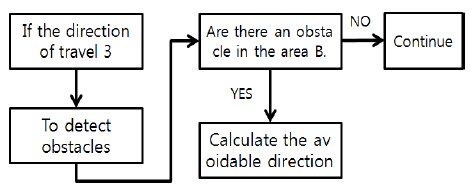
If there is no obstacle on proceeding flight pass and obstacles are found by LRF on both side of the UAV (region A, C) as shown in Figure 7, the aircraft can safely travel on its way (1) without changing the flight direction. Figure 8 shows flowchart of flight direction and avoidance according to obstacles.
On the other hand, if the flight path is straight and the obstacles are found in the region of B and C, the aircraft can not keep going straight (direction 3). If the aircraft travels on the proceeding flight direction, it would be dangerous of collision with obstacle B, so the MCU will calculate the appropriate direction for the aircraft to avoid the barrier. Since obstacle B was detected with C at the same time, there is a danger of collision when it moves to region C. Thus as the system produces PWM signal to avoid on safe region A, the aircraft will changes the flight direction to safe direction 4 as shown in Figure 9.
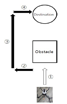
The aircraft requires a system that can revert to the original path after successfully avoiding the obstacle as shown in Figure 10. If the aircraft is moving straight forward and is confronted with obstacles, the aircraft will detect and decide where to avoid. After avoiding the barrier, it needs to go back to the original path to go to the destination. In this study, we used counting function in order to figure out how much the craft will move to the avoiding direction, while the aircraft was avoiding. During avoiding, MCU saves numbers at every 100ms of specific number lines. After that, when it finishes to avoid the obstacle, the aircraft checks how much distance it was far away from the original path by counting number lines and then it makes moving the same distance back to the original path as equal as counting number.
3. Experimental Results
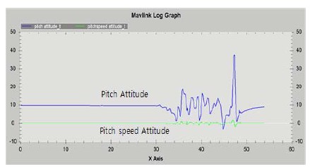
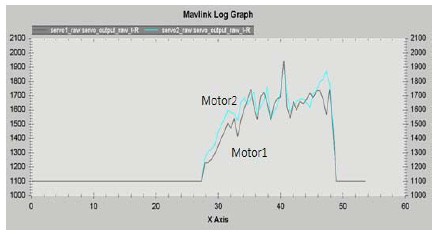
After APM2 saves the flight records (control signals from the transmitter and the change of location through GPS etc), it provides the records to the use. Thus, it is possible to analyze the saved data when the obstacle was detected and which avoiding signals were sent in the actual flight. There are four kinds of data that we should consider as shown in Figure 10. There are the data (①) that flies straight to the first destination, the avoiding direction data (②, ③) and the data (④) for returning to the destination. Data of ① can be recognized by analyzing the date of the pitch movement which is the movement of the craft to move forward. Figure 11 shows the attitude value of the pitch and Figure 12 is the output value of the motor. The motor 1 is the output value of the front motor and the motor 2 is the output value of the back motor.
In the case of pitch movement, the output of motor 2 is more higher than that of motor 1 in the 30~40 range of x-axis as shown in Figure 11. That the output of motor 2, which is located in the backside, is high means that the aircraft is proceeding forward. In these range, the aircraft has the movement of section ① in Figure 10. In the section of data (②) for avoiding, it is the movement for the left-side and the right-side. There is no difference in movement between motor 1 and motor 2 in the range of 40~46.
Lastly, in the section of data (③) after avoiding obstacles, the aircraft flies straight to the destination. The plane finishes avoidance of obstacles at 46 position of the x axis and then the output value of motor 2 is more higher than that of motor 1 as shown in Figure 12.
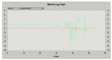
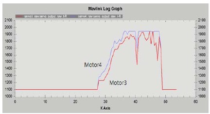
Next, it can be figured out the left and right movements of the aircraft by observing the data through roll movement. The avoiding direction of data (②), and the movement back to the destination of data (④) are the left and right movement of the aircraft. When the avoiding direction is left, the craft does not do pitch movement (moving forward) but do roll movement (left and right) as shown in Figure 13. Motor 3 locates on the left and motor 4 locates on the right. If the output of motor 4 is more higher than that of motor 3, the aircraft moves to the left. T
In the 40~46 range of x-axis, the output of the motor 3 is smaller than that of motor 4 as shown in Figure 14. We can also observe that the output of motor 4 stays in the maximum value. Due to this difference, the aircraft moves only left.
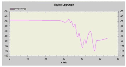
In the section of data (④) for returning to the original destination, there was an error. Because the aircraft didn't control the movement of yaw, we can realize that the output of yaw movement changes over the 30~55 range of x-axis while the aircraft flies as shown in Figure 15. Therefore we came to stop flight experiment because of danger of collision due to errors in yaw value. To overcome these problem, we are necessary to make new QRH system. After making new QRH system, we are planning to do extra experiment for reverting back to the original path.
4. Conclusion
In this study, we proposed a system to avoid obstacles automatically by measuring the angle and distance of the obstacle. We used a laser range finder as an obstacle detector to navigate to the destination automatically. By using LRF devices, the proposed system can observe a large range of flight path and decide on the safest avoiding direction depending on the location of the barrier. The selector system is also used to control the craft in the case of emergencies and to increase safety of avoidance. The automatic avoiding algorithm used in this study can be well applied in the case of complicated forms, random obstacles. And in the case of unavoidable obstacles, the aircraft can safely avoid by using hovering. Although we didn't do experiment for reverting back to the original path, we can achieve our target by making a modified QRH system for yaw control.
Acknowledgments
This work was supported by research fund of Korea Maritime and Ocean University.
Notes
References
-
P. Tatham, “An investigation into the suitability of the use of unmanned aerial vehicle system (UAVs) to support the initial needs assessment process in rapid onset humanitarian disasters”, International Journal of Risk Assessment and Management, 13(1), p60-78, (2009).
[https://doi.org/10.1504/IJRAM.2009.026391]

-
L. Guo, Q. Zhang, and S. Han, “Agricultural machinery safety alert system using ultrasonic sensors”, Journal of Agricultural Safety and Health, 8(4), p385-396, (2002).
[https://doi.org/10.13031/2013.10219]

-
T. Kato, Y. Ninomiya, and I. Masaki, “An obstacle detection method by fusion of radar and motion stereo”, IEEE Transactions on Intelligent Transportation Systems, 182(188), p3-3, (2002).
[https://doi.org/10.1109/TITS.2002.802932]

-
Y. Fang, I. Masaki, and B. Horn, “Depth-based target segmentation for intelligent vehicles: fusion of radar and binocular stereo”, IEEE Transactions on Intelligent Transportation Systems, 3(3), p196-202, (2002).
[https://doi.org/10.1109/TITS.2002.802926]

-
R. Aufrère, J. Gowdy, C. Mertz, and C. Thorpe, “Perception for collision avoidance and autonomous driving”, Mechatronics, 13(10), p1149-1161, (2003).
[https://doi.org/10.1016/S0957-4158(03)00047-3]

-
R. Manduchi, A. Castano, A. Talukder, and L. Matthies, “Obstacle detection and terrain classification for autonomous off-road navigation”, Autonomous Robots, 18, p81-102, (2005).
[https://doi.org/10.1023/B:AURO.0000047286.62481.1d]

-
M. Kise, Q. Zhang, N. Noguchi, “An obstacle identification algorithm for a laser range finder-based obstacle detector”, Transactions of the American Society of Agricultural Engineers, (2005), 48(3), p1269-1278.
[https://doi.org/10.13031/2013.18491]

-
M. S. Geyer, and E. N. Johnson, “3D obstacle avoidance in adversarial environments for unmanned aerial vehicles,”, Proceedings of AIAA Guidance, Navigation and Control Conference and Exhibit, p1-12, (2006), (in USA).
[https://doi.org/10.2514/6.2006-6542]

