
Design and development of a high-speed large-format FDM system with independent four-Z-axis control

Copyright © The Korean Society of Marine Engineering
This is an Open Access article distributed under the terms of the Creative Commons Attribution Non-Commercial License (http://creativecommons.org/licenses/by-nc/3.0), which permits unrestricted non-commercial use, distribution, and reproduction in any medium, provided the original work is properly cited.
Abstract
Large-format fused deposition modeling (FDM) systems enable fabrication of meter-scale parts but suffer from limited speed, poor bed-leveling accuracy, and reduced stability as build size increases. Most commercial systems rely on low print speeds and mechanically coupled Z-axis designs, limiting productivity and dimensional accuracy for large components. This study presents the design and development of a high-speed large-format FDM system with a build volume of 1,100 × 1,100 × 1,000 mm, addressing scalability, throughput, and bed-leveling issues. The system features a square large-area build platform, high-speed extrusion up to 400 mm/s, an open-chamber structure, and independent control of four Z-axis motors at the gantry corners. This multi-Z configuration compensates for bed tilt and twist, improving first-layer uniformity across the build area. A high-throughput material extrusion system was implemented using a direct-drive dual-gear feeder and an extended melt-zone hot end. Performance was evaluated through mechanical calibration, bed-leveling accuracy tests, and volumetric flow measurements. Results demonstrate stable long-duration printing, consistent first-layer quality, and reliable extrusion at high speeds. The proposed system improves productivity and reliability in large-format FDM and provides a scalable architecture for next-generation additive manufacturing.
Keywords:
Large-format FDM, High-speed additive manufacturing, Independent Z-axis control, Bed Leveling accuracy, Material extrusion, Volumetric flow rate1. Introduction
The Fourth Industrial Revolution (Industry 4.0) is driving a fundamental transformation of the manufacturing sector through the convergence of IoT, artificial intelligence, robotics, and automation technologies. Within this broader digital transition, additive manufacturing (AM) has emerged as a core technology by enabling greater design freedom, manufacturing flexibility, and fast production speeds. In particular, fused deposition modeling (FDM) has become the most widely used process for prototyping and small-batch customized production thanks to its relatively low equipment cost, accessibility, and compatibility with a broad range of thermoplastic materials. AM eliminates the need for mold-based production, and—through process optimization—supports automation and real-time control, thereby realizing the Industry 4.0 imperatives of digitalization, flexibility, and agile manufacturing. Moreover, because it allows rapid responses to design changes and scalable mass customization, AM is establishing a new standard for modern manufacturing [1]-[3].
3D printing has expanded far beyond its early role in rapid prototyping and is now used for direct manufacturing of end-use components in aerospace, automotive, medical, construction, and the marine and shipbuilding industries. In aerospace, automotive, and energy applications, AM has been adopted for structural components, cooling devices, and exhaust systems to achieve weight reduction, cost savings, and shorter production times. For example, in one aircraft duct application, sixteen separate parts were redesigned and produced as a single integrated component, dramatically reducing assembly complexity. The importance of AM has also grown rapidly in the marine and shipbuilding sectors, where propellers, structural components, and pipe supports can be fabricated additively, cutting lead times from weeks to days compared with conventional methods. The U.S. Navy has equipped multiple vessels with onboard 3D printers to manufacture and replace needed parts at sea, significantly reducing downtime and improving operational efficiency [4]-[6].
Most commercial desktop FDM printers offer limited build volumes in the range of 200 mm × 200 mm × 200 mm up to roughly 300 mm × 300 mm × 400 mm. Even professional large-format FDM systems present notable constraints. The Modix Big-60 V4 provides a 600 mm × 600 mm × 660 mm build volume but a maximum print speed of only 200 mm/s. The BigRep PRO offers a 1,000 mm × 500 mm × 500 mm build envelope, which restricts fabrication of wide, square parts, and its print speed is likewise on the order of 200 mm/s. Such size limitations make it impossible to produce truly large parts—such as square geometries or components exceeding one meter in their maximum dimension—in a single build; complex, large components must be segmented, printed separately, and subsequently assembled. This leads to extra assembly steps, weakened joints, and longer overall production times. Furthermore, both small and large FDM platforms face an inherent trade-off between precision and print speed. Parts that require high precision often demand slower print speeds (50–100 mm/s), which increases production time, whereas increasing speed tends to degrade surface quality and dimensional accuracy [4]-[5][7].
These industrial demands go beyond simply increasing part size: they require systems capable of rapidly producing large monolithic components, integrating complex internal architectures, and simultaneously achieving high precision and repeatability.
Large-scale FDM of big parts introduces several technical challenges distinct from those encountered at smaller scales. First, thermal management and deformation: during cooling, large parts are prone to non-uniform temperature distributions that produce interlayer deformation and intralayer deflection. Materials with higher coefficients of thermal expansion—such as ABS (approximately 6 × 10⁻⁵/K)—can exhibit severe warpage and twisting in large components. These thermal stresses significantly compromise dimensional accuracy and may even force the build to abort. Current commercial large-format printers have not fully solved these issues; most rely on closed chambers to mitigate them only partially [8].
Second, maintaining dimensional accuracy is difficult. In FDM, parameters such as layer thickness, print speed, and raster angle affect surface roughness and dimensional fidelity. Parameter optimization becomes more complex at larger scales, and specific geometries—like circular features and holes—can show errors exceeding 5%. In addition, limitations in the extrusion flow control of low-cost FDM systems make it challenging to produce parts of diverse sizes and shapes with high precision [9]-[12].
Third, long build times create reliability concerns. Large parts often require tens to hundreds of hours to print, during which filament feeding errors, nozzle clogging, and other equipment faults can accumulate. On very large build platforms—such as 1,100 mm × 1,100 mm—the longer travel distances of the printhead make it even more difficult to maintain mechanical precision [13]-[14].
One of AM’s greatest advantages is part consolidation—the ability to manufacture what would otherwise be multiple components as a single integrated part. This can eliminate or drastically reduce assembly operations and cut the total part count. For example, in the aircraft duct case mentioned earlier, sixteen parts were consolidated into one, removing assembly complexity altogether. Enabling monolithic fabrication at large scales would extend these benefits even further, particularly for high-performance components requiring complex internal cooling channels, lattice structures, and functional integration—fundamentally reshaping how such parts are designed and produced [15].
In recent years, extensive research has targeted improvements in the precision and quality of FDM. Chen et al. [8] employed thermomechanical finite-element analysis to simulate and predict warpage in large components produced by FDM; they found that interlayer deformation is more severe than intralayer deflection and that non-uniform temperature distribution is a primary driver of residual thermal stresses and final distortion—offering critical guidance for thermal-management system design at large scales. Sukindar et al. [9] used the Taguchi method to analyze how layer thickness, print speed, and raster angle affect surface roughness; in PLA-aluminum composites, layer thickness and raster angle had the strongest influence, and circular holes exhibited dimensional errors greater than 5%, underscoring the importance of precision control for large parts. Chojnacki et al. [10] compared prototyping accuracy across FDM, DLP, and SLS, showing that while FDM excels in accessibility and cost-effectiveness, achieving consistent quality hinges more on minimizing stochastic, in-process errors than on material choice or nominal printer settings. Yang et al. [11] proposed an AM-based part-consolidation methodology that jointly considers structural optimization and functional integration; in a triple-clamp case study, the part count was reduced from 19 to 7 while simultaneously cutting mass by 20%. Li et al. [12] introduced an in-process monitoring and control approach for improving the dimensional accuracy of extrusion-based 3D printing, demonstrating that real-time feedback can reduce geometric inaccuracies and highlighting the importance of closed-loop control. Most recently, Kang et al. [16] proposed adaptive-nozzle 3D printing (AN3DP), which dynamically varies nozzle size and geometry to enable multi-scale deposition; by controlling filament diameter through the nozzle in real time, the method partially mitigates the speed-versus-precision trade-off.
Despite these advances, most prior work focuses on small-scale parts or on theoretical analyses. Robust, precise FDM at truly large scales—beyond a 1,100 mm × 1,100 mm build area—still lacks integrated system design and rigorous experimental validation. In particular, studies remain scarce on large FDM printers that simultaneously satisfy (i) a square 1,100 mm × 1,100 mm build platform, (ii) high-speed extrusion (≥ 400 mm/s), (iii) stability in an open-chamber architecture, (iv) precise bed leveling via independently driven Z-axes, and (v) long-duration process stability for PLA.
Compared with existing large-format FDM systems or multi-Z-based platforms, the developed system has the following distinguishing features. First, the system provides a square large-format build volume of 1,100 × 1,100 × 1,000 mm, enabling meter-scale parts to be fabricated in a single printing process. Second, the system was designed for a maximum printing speed of 400 mm/s to reduce the long build time typically associated with large-format FDM. Third, four Z-axis lead screws are independently controlled to compensate for corner height deviations of the large build platform. Unlike mechanically synchronized Z-axis structures, this configuration allows each corner height to be adjusted individually, which is advantageous for improving first-layer uniformity over a large build area. Fourth, the system adopts an open-chamber and non-heated fixed build platform for PLA printing, and its dimensional accuracy, bed-leveling performance, process parameters, and 50-h continuous printing stability were experimentally evaluated using the same platform. Therefore, the contribution of this study lies not only in applying individual design elements, but also in integrating the mechanical structure, control system, extrusion system, bed-leveling function, and reliability evaluation required for high-speed large-format FDM printing.
To ensure cost effectiveness, ease of fabrication, and scalability, the design maximizes the use of industrial aluminum profiles and standard off-the-shelf components.
Using the developed printer, we verify:
① The stability of the mechanical structure and control system.
② Optimization of PLA printing parameters—nozzle diameter (0.6–1.2 mm), print speed (100–400 mm/s), and temperature profiles—to determine optimal settings.
③ The performance of the bed-leveling system, including corner-to-corner height deviations and tilt-compensation accuracy.
④ Long-term reliability through continuous prints lasting at least 50 hours.
2. Design and Implementation of a Large-Format FDM 3D Printer
The design requirements of the developed large-format FDM system are summarized in Table 1. These requirements were established to achieve large-area fabrication, high-speed printing, automatic bed leveling, and long-duration printing stability in an open-chamber PLA printing environment.

Design requirements of the developed large-format FDM system
2.1 Overall System Architecture
The developed printer adopts a Cartesian motion architecture in which the X-axis is driven by two motors and the Y-axis is driven by two motors to enable stable large-area motion. As shown in Figure 1, the XY stage uses two independent belt loops and is electrically synchronized (dual-drive, master–slave) to equalize belt tension at both ends of each axis and suppress racking during high-speed motion. A fixed build platform is supported by a four-point, lead-screw-driven Z system with independent Z motors for active bed leveling. The overall structure employs a four-post frame with vertical columns at the four corners to provide a simplified architecture and high manufacturing efficiency.
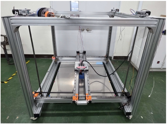
Overall structure of the large-format FDM 3D printer (Cartesian dual-loop belt-driven XY and four-post frame)
2.2 Mechanical Design
In Figure 2, the frame employs a four-post structure made of 80 × 80 mm aluminum profiles, with an overall envelope size of 1,500 mm × 1,500 mm × 1,200 mm. Upper and lower cross-bracing is applied to prevent torsional deformation. The frame was optimized to achieve a target deflection of < 0.15 mm under an expected load of 50 kg (bed + printed part).
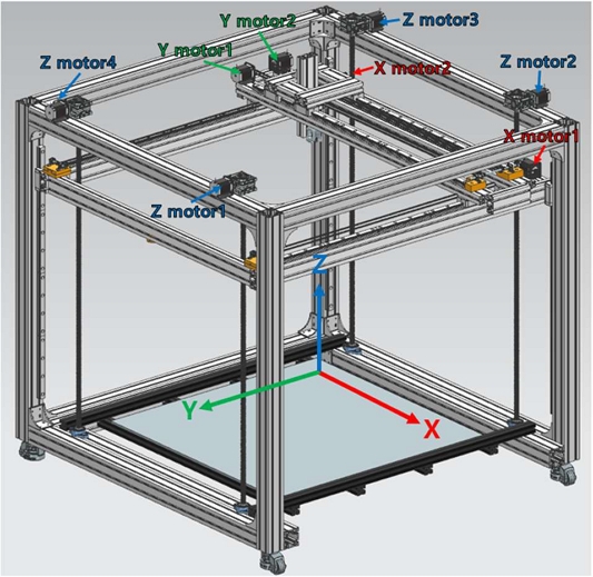
Four-post frame and four-point Z-axis lead-screw system with Cartesian dual-loop belt-driven XY
The X-axis and Y-axis are each driven by two stepper motors. The XY system uses two belt loops and GT2 belts (10 mm width, steel-reinforced core) to achieve high-speed and high-precision motion over a 1,100 mm stroke. linear guides are used to support large-stroke motion with reduced deflection and improved repeatability. The motion system supports a maximum speed of 400 mm/s and an acceleration of 5,000 mm/s². It is organized in the Table 2.
XY-axis specifications
Z-Axis and Bed-Leveling System are as follows: TR20 × 4 lead screws (pitch: 4 mm) are placed at the four corners, and each lead screw is driven by an independent stepper motor. By combining the high-speed capability of the belt-driven XY stage with the precision and load-bearing capacity of the lead-screw-driven Z stage, the printer enables stable large-format printing.
Bed leveling is performed by probing the bed using an 81-point (9 × 9) grid with 110 mm spacing, estimating the bed plane via least squares, and applying per-motor compensation. In firmware, the four-Z leveling routine is implemented via Marlin G34 (Z Steppers Auto-Alignment), and is referred to as QGL (Quad Gantry Leveling) in this paper for brevity. It is organized in the Table 3.
Z-axis specifications
Bed-leveling procedure is as follows:
① Measure Z height on a 9 × 9 (81-point) probing grid with 110 mm spacing
② Compute the best-fit bed plane using a least-squares method
③ Store and compensate the offsets for each of the four Z motors (G34-based auto-alignment)
2.3 Extrusion and Thermal System
For clarity in this paper, the system is described using cold-end and hot-end terminology: the cold-end transports solid filament, while the hot-end (liquefier) melts and extrudes it through the nozzle. In Figure 3, the two zones are thermally separated by a heat (thermal) break, which establishes a steep thermal gradient required for stable melting and to mitigate heat transfer toward the cold side (heat creep).
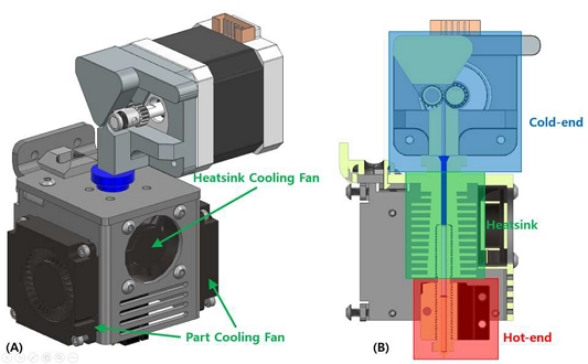
(A) Extrusion and Thermal System, (B) Section View
Figure 3 summarizes the extrusion and thermal system architecture. The system is divided into:
① Cold end (direct-drive feeding unit),
② Hot end (assembled liquefier + nozzle with a long melt zone),
③ Cooling subsystems (heatsink cooling and part cooling), and
④ Thermal control and throughput characterization.
To support high-throughput deposition for large parts, the hot end adopts a long melt-zone concept, where the heated region is extended to increase the residence time of filament in the liquefier and improve heat transfer into the polymer, enabling higher melt rate and volumetric throughput.
A conventional assembled hot end architecture was employed, consisting of a heatsink, heat break, heater block, and nozzle. The heat break provides thermal isolation between the cold and hot sides, maintaining a steep temperature gradient required for stable extrusion.
The hot end was designed based on a long melt-zone configuration to support high-throughput extrusion, which is known to mitigate flow limitations associated with large nozzle diameters and thick-layer deposition [17]. The system was equipped with interchangeable nozzles to accommodate both fine-feature printing and high-throughput operation.
A direct-drive feeding mechanism was adopted to improve extrusion controllability by minimizing filament path compliance. The cold end employs a dual-drive gear configuration, in which the filament is actively driven from both sides to enhance traction and reduce slippage under high extrusion loads. This configuration contributes to stable material feeding during high-speed and high-throughput printing.
Cooling functions were separated into hot-end heatsink cooling and part cooling. Heatsink cooling was implemented to suppress heat creep and stabilize the thermal boundary at the heat break, while part cooling was applied to accelerate solidification of deposited material and improve geometric fidelity. This separation was considered essential for stable operation in the open-chamber configuration.
Hot-end temperature was regulated using closed-loop control, and system throughput was characterized using the volumetric flow rate, defined as the volume of molten polymer extruded per unit time. The maximum practical volumetric flow rate was determined using an incremental flow test, in which the commanded flow was gradually increased until consistent flow limitation was observed.
The resulting volumetric flow limit was used to constrain feasible printing conditions according to:
| (1) |
where v is print speed (mm/s), Q is volumetric flow rate (㎣/s), w is line width (mm), and h is layer height (mm). This relation was used to choose feasible combinations of nozzle diameter, line width, layer height, and speed under the throughput constraint of the long melt-zone hot end.
2.4 Control System
The control system of the developed large-format FDM printer was designed to ensure stable motion control, robust multi-axis actuation, and reliable long-duration operation for meter-scale printing. Compared to desktop-class systems, large-format printers impose higher demands due to long travel distances, multi-point Z-axis actuation, and increased material throughput. Accordingly, a scalable and robust control architecture was adopted.
The system is based on a 32-bit microcontroller–based control platform, providing sufficient computational capability for real-time multi-axis motion control, thermal regulation, and sensor management. The architecture supports flexible integration of external motor drivers and peripheral devices, enabling independent control of multiple axes, heaters, fans, and safety-related sensors.
To meet differing performance requirements, the motor drive system employs a hybrid configuration. High-torque motion axes are driven using external stepper drivers, while the extrusion axis is controlled by an on-board driver. This approach balances torque capacity, thermal stability, and wiring simplicity.
Dual-motor synchronized drives are used for the X and Y axes, while the Z axis is actuated by four independently controlled motors, enabling automatic compensation of bed tilt and torsional deformation during leveling.
Electronic synchronization is applied to dual-motor axes to maintain coordinated motion over long travel distances. Independent control of the four Z-axis motors enables precise bed-leveling correction, which is particularly important for maintaining first-layer consistency in large-format printing.
The control system operates on an open-source firmware platform configured for large-scale FDM printing. Key functions include multi-Z-axis leveling, extrusion compensation during dynamic motion, vibration suppression for high-speed operation, and integrated safety monitoring. These functions support stable printing performance and reliability during extended print durations.
3. Experimental Methods
The experiments were conducted from four perspectives: verification of the mechanical structure and control system stability, optimization of PLA printing parameters, evaluation of the bed leveling system performance, and assessment of system reliability during long-duration printing. Table 4 shows a summary of the experimental methods.
Summary of Experimental Methods
3.1 Experimental Setup and Common Conditions
The experiments were conducted using a large-scale FDM 3D printer with a build volume of 1,100 mm × 1,100 mm × 1,000 mm. The printer adopts an open-frame structure with a non-heated fixed build platform. The XY motion system is based on GT2 belt drives with a belt width of 10 mm, where both the X and Y axes are driven by dual motors to ensure stable motion over long travel distances. The Z axis consists of four TR20×4 lead screws, each driven by an independent motor, enabling automatic bed leveling through multi-point height correction.
Dimensional measurements were performed using a digital caliper with a resolution of 0.01 mm and a dial gauge of the same resolution. Surface quality was evaluated using a surface roughness tester, while temperature monitoring during and after printing was carried out using thermocouples or an infrared thermometer.
All experiments were conducted using PLA filament with a nominal diameter of 1.75 mm and a dimensional tolerance of ±0.03 mm. Unless otherwise specified, the nozzle temperature was set to 210 °C, the layer height to 0.2 mm, and the infill density to 20% with a rectilinear pattern. A non-heated PEI-coated build plate was used, and all experiments were performed under ambient indoor conditions with a temperature range of 20–25 °C and natural convection.
3.2 Verification of Mechanical Structure and Control System Stability
Positioning accuracy and repeatability were evaluated using cube specimens with dimensions of 100 mm × 100 mm × 100 mm and beam specimens with a length of 500 mm. Specimens were printed at both the center and corner regions of the build platform. Dimensional measurements along the X, Y, and Z directions were performed three times for each specimen using a digital caliper, and the mean values and standard deviations were calculated.
To evaluate repeatability, the same G-code was printed five times under identical conditions, and dimensional deviations at corresponding locations were analyzed. Absolute dimensional accuracy was assessed with an acceptance criterion of ±0.3 mm, while repeatability was evaluated based on a standard deviation threshold of 0.1 mm.
3.3 Optimization of PLA Printing Parameters
The selected control factors included nozzle diameter, printing speed, and nozzle temperature. Nozzle diameters were set to 0.6, 0.8, 1.0, and 1.2 mm, and printing speeds ranged from 100 to 400 mm/s. Nozzle temperatures of 200, 210, and 220 °C were considered as baseline conditions, and the experiment was conducted by gradually increasing the temperature under high-speed printing conditions. To reasonably limit the number of experiments, an orthogonal array design or a nozzle-specific speed–temperature matrix was applied.
Dimensional accuracy in the parameter optimization experiment was evaluated using 20 mm × 20 mm × 20 mm cube specimens. The 20 mm cube specimen used for the parameter optimization experiment had the same geometry and measurement-position definition as the 100 mm cube specimen shown in Figure 4(a), except for the nominal size. After printing, each specimen was cooled to room temperature and measured using a digital caliper. The dimensions were measured at four positions in each axis, denoted as X1–X4, Y1–Y4, and Z1–Z4. The mean value of the four measurements in each axis was used as the representative dimension of that axis. The dimensional error for each axis was calculated as the difference between the representative dimension and the nominal dimension of 20 mm. The mean absolute error (MAE) was calculated as follows:
| (2) |
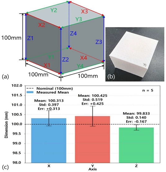
Dimensional accuracy evaluation of the 100 mm cube specimen: (a) specimen geometry and measurement positions; (b) printed specimen; (c) dimensional error results
where |eX|, |eY|, and |eZ| are the mean dimensional errors in the X, Y, and Z directions, respectively. The parameter set with the lowest MAE was selected as the optimal condition considering both dimensional accuracy and printing productivity.
Test models were printed for each combination of nozzle diameter, printing speed, and nozzle temperature. After printing, specimens were allowed to cool to room temperature before dimensional measurements were conducted. The optimal parameter set was selected by considering the trade-off between printing speed and print quality.
3.4 Evaluation of Bed Leveling System Performance
Z-axis heights at the four corners of the build platform were measured using a dial gauge before and after the execution of quad gantry leveling (QGL). Height differences between corners were calculated, and the effectiveness of QGL was evaluated based on the reduction of corner height deviations. Measurements were repeated ten times to assess consistency, with a target standard deviation of approximately 0.01 mm.
3.5 Long-Duration Printing Stability Assessment
Test models included a large plate-type structure with dimensions of approximately 800 mm × 800 mm × 20 mm or an array of multiple medium-sized parts distributed across the build platform. Printing conditions were selected based on the results of the parameter optimization experiments, with a nozzle diameter of approximately 0.8 mm, printing speeds between 200 and 300 mm/s, nozzle temperatures ranging from 210 to 220 °C, and layer heights between 0.3 and 0.4 mm. The generated G-code was configured to ensure a total printing time exceeding 50 h.
During printing, the system was continuously monitored for nozzle clogging, filament feeding errors, axis-related issues such as layer shifting, and abnormal temperature rise in the control electronics and motors. After completion of printing, dimensional accuracy was measured at multiple locations to evaluate accumulated error over long-duration operation. Interlayer defects, warping, delamination, and surface quality variations between early and final layers were also examined. In addition, system logs were analyzed to identify failure events and their root causes, and observed failure modes were classified to assess system reliability both qualitatively and quantitatively.
4. Experimental Result
4.1 Mechanical Structure and Control System Stability
Figure 4 shows the dimensional accuracy and repeatability results obtained using 100 mm × 100 mm × 100 mm cube specimens. For each specimen, the dimensions were measured at a total of 12 positions, denoted as X1–X4, Y1–Y4, and Z1–Z4. The mean value of the four measurements in each axis was used as the representative dimension of that axis. The same G-code was printed five times (n=5) under identical conditions, and the mean dimensional error and standard deviation were calculated for each axis.
The 100 mm cube test showed mean dimensional errors of +0.3135 mm, +0.4255 mm, and -0.1665 mm in the X, Y, and Z directions, respectively. The X and Y-axis errors were larger than the Z-axis error. Since the Z-axis is driven by four lead screws whereas the X and Y-axes are driven by long-span belt transmission systems, the difference in drive mechanism may affect the dimensional error characteristics. This result is further discussed in Section 5 in relation to the dynamic characteristics of the long-span belt-driven gantry system.
To verify system reliability for large-scale components, 500 mm beam specimens were analyzed to identify cumulative errors during long-distance travel. Figure 5 shows the dimensional accuracy results obtained using 20 mm × 20 mm × 500 mm beam specimens to evaluate cumulative dimensional error over a long printing distance. The long direction of the beam specimen was defined as the Z-axis direction. The same measurement-position definition as that used for Figure 4 was applied, and the dimensions were measured at X1–X4, Y1–Y4, and Z1–Z4. The mean value of the four measurements in each axis was used to calculate the representative dimension and dimensional error of that axis.
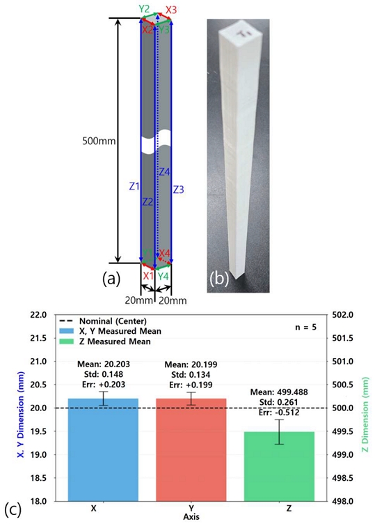
Dimensional accuracy evaluation of the 500 mm beam specimen: (a) specimen geometry and measurement positions; (b) printed specimen; (c) dimensional error results
For the 20 mm × 20 mm × 500 mm beam specimen, the mean dimensional errors were +0.203 mm, +0.199 mm, and -0.5125 mm in the X, Y, and Z directions, respectively. The Z-axis corresponds to the long direction of the beam specimen, and the -0.5125 mm deviation corresponds to a relative error of approximately 0.1% over the 500 mm length. This negative deviation is discussed in Section 5 in relation to cooling shrinkage and accumulated dimensional change during long-distance deposition.
4.2 Results of PLA Printing Parameter Optimization
Figure 6 presents the MAE results calculated using the measurement method described in Section 3.3. The results show the influence of nozzle diameter, printing speed, and nozzle temperature on the dimensional accuracy of the 20 mm cube specimens.
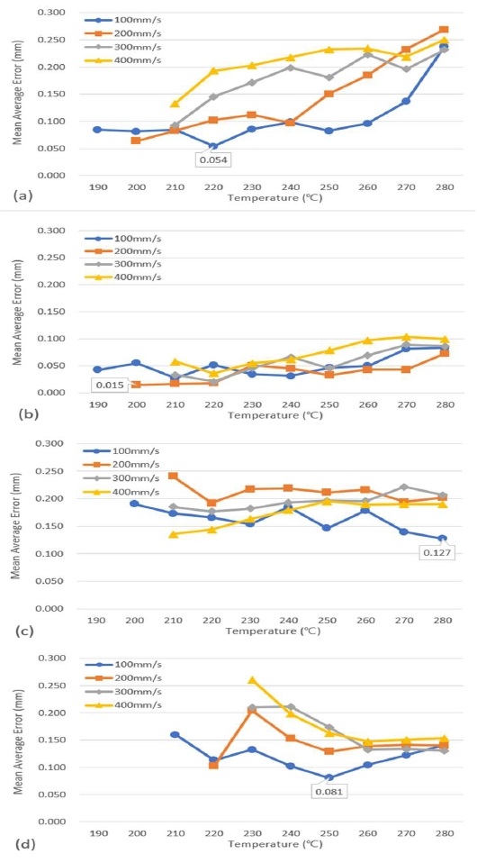
Mean Average Error (MAE) according to parameters Nozzle Size: (a) 0.6mm, (b) 0.8mm, (c) 1.0mm, (d) 1.2mm
Experimental results showed that while productivity improved as the nozzle diameter increased, overall dimensional error tended to increase. However, an optimal point was discovered where the error decreased sharply within a specific temperature range. Based on a combined evaluation of dimensional accuracy, surface roughness, and printing time, an optimal parameter set was identified in terms of balancing print quality and productivity. The selected conditions consisted of a nozzle diameter of 0.8 mm, a printing speed of 200 mm/s, and a nozzle temperature of 200 ℃. Under these conditions, the average dimensional error was 0.0148 mm. The selected parameter set was subsequently applied to the long-duration printing experiments and large-scale part fabrication.
4.3 Bed Leveling System Performance
The measured corner heights before and after the execution of quad gantry leveling (QGL) are summarized in Table 5.
Corner height measurements before and after QGL
Before QGL, the maximum height deviation across the system was measured at 1.092 mm. After the calibration process, this deviation was reduced to 0.045 mm, successfully meeting the target criterion of < 0.05 mm. This result demonstrates that a stable mechanical leveling has been achieved over the 1,100 mm × 1,100 mm build area.
4.4 Long-Duration Printing Stability
To print the experimental samples, printing was performed for 8 hours a day for 25 days, and to print the large samples, printing was performed continuously for 50 hours. However, no abnormal symptoms such as partial nozzle clogging, filament feed slip, layer shift, temperature abnormalities, or printing stoppage occurred.
5. Discussion
Compared with previous studies that primarily addressed thermal deformation, dimensional accuracy, process monitoring, or individual technical challenges in large-format FDM systems, the present study focuses on the integrated development and experimental evaluation of a meter-scale FDM platform. The developed system combines a square 1,100 × 1,100 mm build platform, high-speed printing capability up to 400 mm/s, independent four-Z-axis leveling, and long-duration printing evaluation in a single platform. This integrated approach distinguishes the proposed system from studies or systems that address only individual aspects such as build-volume enlargement, leveling control, or process optimization. In particular, the experimental evaluation of dimensional accuracy, QGL-based corner height correction, parameter optimization, and continuous printing stability provides practical validation of the proposed large-format FDM architecture.
In the 100 mm cube test shown in Figure 4, the mean dimensional errors were +0.3135 mm, +0.4255 mm, and -0.1665 mm in the X, Y, and Z directions, respectively. The larger X-Y errors compared with the Z-axis error can be interpreted in relation to the difference in drive mechanisms between the axis systems. In the developed system, the Z-axis is driven by four lead screws, whereas the X- and Y-axes use long-span belt-driven gantry mechanisms. The lead-screw-driven Z-axis provides relatively high position-holding characteristics, while the long-span belt-driven X-Y axes can be affected by belt tension, belt elasticity, pulley alignment, gantry stiffness, and dynamic response during high-speed acceleration and deceleration.
This interpretation is also related to previous studies on gantry-type FDM/FFF systems. Edoimioya et al. [18] reported that racking motion in H-frame 3D printers can limit dynamic accuracy during high-speed and high-acceleration motion, and demonstrated that racking compensation can improve printed shape accuracy. Jensen et al. [19] also experimentally reported that the print bed and print head gantry are vibration-sensitive components in extrusion-type additive manufacturing systems, and that vibration can affect print quality. Therefore, the relatively larger X-Y dimensional errors observed in this study can be interpreted in relation to the dynamic characteristics of the long-span belt-driven gantry structure, high-speed motion conditions, structural stiffness, and vibration effects. In future work, the dominant sources of X-Y dimensional error will be quantitatively investigated by independently varying belt tension, acceleration and jerk conditions, pulley alignment, and frame deformation.
In Figure 5, the mean dimensional errors of the 20 mm × 20 mm × 500 mm beam specimen were +0.2030 mm, +0.1990 mm, and -0.5125 mm in the X, Y, and Z directions, respectively. In this specimen, the Z-axis corresponds to the long direction, and the Z-directional deviation of -0.5125 mm corresponds to a relative error of approximately 0.1% over the 500 mm length. This negative dimensional deviation can be interpreted in relation to cooling shrinkage in the FDM process and accumulated dimensional change during long-distance deposition.
In the FDM process, the molten or softened filament is deposited and subsequently cools to room temperature. During this cooling process, thermal contraction and residual stress can develop within the printed part. For long specimens, local contraction along individual deposited roads may accumulate in the length direction and appear as a measurable reduction in the final dimension. Chen et al. [8] reported that non-uniform temperature distribution in large FDM parts can be a major cause of residual thermal stress and final deformation. Armillotta et al. [20] also explained that thermal cycles in FDM can generate distortions such as warpage in printed parts. Syrlybayev et al. [21] likewise reported that rapid heating and cooling during the FDM process can generate highly non-uniform internal stresses, which are associated with warpage deformation.
Because the beam specimen in this study has a long Z-axis length of 500 mm, local cooling shrinkage and dimensional changes along deposited roads may accumulate in the length direction and appear as a negative dimensional deviation in the Z direction. In addition, because the developed system uses an open-chamber and non-heated bed configuration, the cooling conditions across a large part may not be uniform. Therefore, the Z-directional dimensional reduction observed in Figure 5 is interpreted as the combined result of PLA cooling shrinkage, accumulated dimensional change during long-distance deposition, and the thermal characteristics of the open printing environment.
The parameter optimization study revealed a clear trade-off between productivity and precision. While larger nozzles (1.0 mm and 1.2 mm) significantly reduced print time, they introduced greater dimensional variance. However, the identification of an "optimal sweet spot"—a 0.8 mm nozzle at 200 mm/s and 200 ℃—is a significant finding. This specific configuration allows for an MAE of 0.0148 mm, proving that high-speed, large-scale manufacturing does not necessarily require a compromise in quality. This balance is critical for the practical application of the printer in research and development environments where both turnaround time and accuracy are paramount.
The QGL system's ability to reduce corner height deviation from 1.092 mm to 0.045 mm is a testament to the effectiveness of the four-point independent Z-axis control. On a 1,100 mm × 1,100 mm build plate, maintaining such sub-micron level adjustments ensures consistent first-layer adhesion, which is the most common failure point in large-scale FDM. Furthermore, the 50-hour continuous printing success validates the thermal management and filament feeding reliability of the system, confirming its readiness for industrial-grade prototyping.
6. Conclusion
This research successfully developed and validated a large-scale FDM 3D printer with a build volume of 1,100 mm × 1,100 mm × 1,000 mm, optimized for high-speed and high-precision R&D applications. Through rigorous experimental validation, the following conclusions were drawn:
1. Mechanical Stability: The system demonstrated stable positioning accuracy. While Z-axis precision was superior, XY-plane deviations were identified as areas for further mechanical refinement. The 500 mm long-distance test confirmed a stable relative error of 0.1%, manageable through software compensation.
2. Process Optimization: Through a comprehensive parameter study, a 0.8 mm nozzle diameter combined with a speed of 200 mm/s and a temperature of 200 ℃ was established as the optimal configuration, yielding a minimal MAE of 0.0148 mm.
3. Leveling and Reliability: The Quad Gantry Leveling (QGL) system achieved a remarkably low corner height difference of 0.045 mm, ensuring a flat build surface across a large area. Long-duration tests (50 hours continuous) proved the system's robustness against common FDM failures such as nozzle clogging or layer shifts.
In conclusion, the developed printer provides a reliable and precise platform for large-scale additive manufacturing. Future research will focus on expanding material compatibility beyond PLA and implementing real-time sensor-based feedback loops to further enhance XY-plane precision during high-speed operation.
Acknowledgments
This research was funded by the Ministry of SMEs and Startups (MSS), Republic of Korea, through the Didimdol R&D Program (RS-2025-16070997), and supported by the Korea Maritime & Ocean University Research Fund in 2025. In addition, this work includes results from a study conducted under the Regional Growth and Talent Development System (Anchor), supported by the Ministry of Education and Busan Metropolitan City (2026-ANCHOR-02-002-004).
Author Contributions
Conceptualization, I. Kim and J. Ko; Methodology, I. Kim and D. Lee; Software, I. Kim; Validation, I. Kim and J. Ko; Formal Analysis, I. Kim and D. Lee; Investigation, I. Kim and D. Lee; Resources, I. Kim; Data Curation, I. Kim; Writing—Original Draft Preparation, I. Kim; Writing—Review & Editing, J. Ko; Visualization, I. Kim; Supervision, J. Ko; Project Administration, J. Ko; Funding Acquisition, J. Ko.
References
-
G. Prashar, H. Vasudev and D. Bhuddhi, “Additive manufacturing: expanding 3D printing horizon in industry 4.0,” International Journal on Interactive Design and Manufacturing, vol. 17, pp. 2221-2235, 2023.
[https://doi.org/10.1007/s12008-022-00956-4]

-
M. Khorasani, J. Loy, A. H. Ghasemi, E. Sharabian, M. Leary, H. Mirafzal, P. Cochrane, B. Rolfe and I. Gibson, “A review of Industry 4.0 and additive manufacturing synergy,” Rapid Prototyping Journal, vol. 28, no. 8, pp. 1462-1475, 2022.
[https://doi.org/10.1108/RPJ-08-2021-0194]
-
U. M. Dilberoglu, B. Gharehpapagh, U. Yaman, and M. Dolen, “The Role of additive manufacturing in the era of Industry 4.0,” Procedia Manufacturing, vol. 11, pp. 545-554, 2017.
[https://doi.org/10.1016/j.promfg.2017.07.148]
-
B. Blakey-Milner, P. Gradl, G. Snedden, M. Brooks, J. Pitot, E. Lopez, M. Leary, F. Berto and A. du Plessis, “Metal additive manufacturing in aerospace: A review,” Materials & Design, vol. 209, 2021.
[https://doi.org/10.1016/j.matdes.2021.110008]
-
M. T. Getachew, M. Z. Shiferaw, and B. S. Ayele, “The current state of the art and advancements, challenges, and future of additive manufacturing in aerospace applications,” Advances in Materials Science and Engineering, vol. 2023, Issue 1, pp. 13, 2023.
[https://doi.org/10.1155/2023/8817006]
-
E. Kostidi and N. Nikitakos, “Is it time for the maritime industry to embrace 3d printed spare parts?,” International Journal on Marine Navigation and Safety of Sea Transportation, vol. 12, no. 3, 2018.
[https://doi.org/10.12716/1001.12.03.16]
-
G. Liu, X. Zhang, X. Chen, Y. He, L. Cheng, M. Huo, J. Yin, F. Hao, S. Chen, P. Wang, S. Yi, L. Wan, Z. Mao, Z. Chen, X. Wang, Z. Cao and J. Lu, “Additive manufacturing of structural materials,” Materials Science and Engineering: R: Reports, vol. 145, 2021.
[https://doi.org/10.1016/j.mser.2020.100596]
-
G. Chen, D. Wang, W. Hua, W. Wu, W. Zhou, and Y. Jin, “Simulating and predicting the part warping in fused deposition modeling by thermal–structural coupling analysis,” 3D Printing and Additive Manufacturing, vol. 10, no. 1, 2023.
[https://doi.org/10.1089/3dp.2021.0119]
-
N. A. Sukindar, A. S. H. Md Yasir, M. D. Azhar, M. A. Md Azhar, N. F. H. Abd Halim, M. H. Sulaiman, A. S. H. Ahmad Sabli, and M. K. A. Mohd Ariffin, “Evaluation of the surface roughness and dimensional accuracy of low-cost 3D-printed parts made of PLA–aluminum,” Heliyon, vol. 10, no. 4, 2024.
[https://doi.org/10.1016/j.heliyon.2024.e25508]
-
B. Chojnacki, A. Chojak, W. Binek, J. Pawlik, and J. Idczak, “Accuracy of 3D printing of the samples in the prototyping of cavity-based metamaterials,” Scientific Reports, vol. 15, no. 13259, 2025.
[https://doi.org/10.1038/s41598-025-98391-4]
-
S. Yang, Y. Tang, and Y. F. Zhao, “A new part consolidation method to embrace the design freedom of additive manufacturing,” Journal of manufacturing Processes, vol. 20, pp. 444-449, 2015.
[https://doi.org/10.1016/j.jmapro.2015.06.024]
-
L. Li, R. McGuan, R. Isaac, P. Kavehhpour, and R. Candler, “Improving precision of material extrusion 3D printing by in-situ monitoring & predicting 3D geometric deviation using conditional adversarial networks,” Additive Manufacturing, vol. 38, no. 101695, 2021.
[https://doi.org/10.1016/j.addma.2020.101695]
-
Y. Fu, A. Downey, L. Yuan, A. Pratt, and Y. Balogun, “In situ monitoring for fused filament fabrication process: A review,” Additive Manufacturing, vol. 38, 2021.
[https://doi.org/10.1016/j.addma.2020.101749]
-
M. H. Ali, S. Kurokawa, E. Shehab, and M. Mukhtarkhanov, “Development of a large-scale multi-extrusion FDM printer, and its challenges,” International Journal of Lightweight Materials and Manufacture, vol. 6, no. 2, pp. 198-213, 2023.
[https://doi.org/10.1016/j.ijlmm.2022.10.001]
-
F. Aliberti, R. Longo, M. Raimondo, R. Pantani, L. Vertuccio, and L. Guadagno, “Additive manufacturing of polymers and composites for applications in aerospace and aeronautics,” Materials Horizons, vol. 13, pp. 532-588, 2025.
[https://doi.org/10.1039/D5MH01403D]
-
S. W. Kang and J. Mueller, “Multiscale 3D printing via active nozzle size and shape control,” Science Advances, vol. 10, no. 23, 2024.
[https://doi.org/10.1126/sciadv.adn7772]
-
F. Cerbe, D. Mahlstedt, M. Sinapius, C. Hühne, and M. Böl, “Relationship between programming stress and residual strain in FDM 4D printing,” Progress in Additive Manufacturing, vol. 9, pp. 123-132, 2024.
[https://doi.org/10.1007/s40964-023-00477-w]
-
N. Edoimioya, K. S. Ramani, and C. E. Okwudire, “Software compensation of undesirable racking motion of H-frame 3D printers using filtered B-splines,” Additive Manufacturing, vol. 47, 102290, 2021.
[https://doi.org/10.1016/j.addma.2021.102290]
-
N. J. Jensen, G. G. Parker, and J. R. Blough, “Base vibration effects on additive manufactured part quality,” Experimental Techniques, vol. 48, pp. 159-170, 2024.
[https://doi.org/10.1007/s40799-023-00629-1]
-
A. Armillotta, M. Bellotti, and M. Cavallaro, “Warpage of FDM parts: Experimental tests and analytic model,” Robotics and Computer-Integrated Manufacturing, vol. 50, pp. 140-152, 2018.
[https://doi.org/10.1016/j.rcim.2017.09.007]
-
D. Syrlybayev, B. Zharylkassyn, A. Seisekulova, A. Perveen, and D. Talamona, “Optimization of the warpage of fused deposition modeling parts using finite element method,” Polymers, vol. 13, no. 21, pp. 3849, 2021.
[https://doi.org/10.3390/polym13213849]