
Upset forging process design of aluminum bolts and forming load evaluation by slab method

Copyright © The Korean Society of Marine Engineering
This is an Open Access article distributed under the terms of the Creative Commons Attribution Non-Commercial License (http://creativecommons.org/licenses/by-nc/3.0), which permits unrestricted non-commercial use, distribution, and reproduction in any medium, provided the original work is properly cited.
Abstract
A process design method for multi-stage cold upset forging of aluminum alloy bolts, along with an analytical approach for predicting the forming load using the slab method, was proposed. The dimensions of the initial workpiece and preform profile were determined by the volume constancy principle and empirical design rules. Process limitations related to the occurrence of defects, such as buckling and cracking, were incorporated to determine the process schedule for cold upset forging. Additionally, the forming load at each stage was calculated with a modified slab method that accounts for the effective deformation near the end of the punch stroke. To assess the validity of the proposed design method and analytical approach, finite element method (FEM) simulations and upset forging experiments were conducted under identical conditions. The FEM predictions of deformed head shapes closely matched the experimental results, with no forming defects observed. Moreover, the analytical model could evaluate the forming loads with an error of approximately 1% relative to FEM results. The method can be used for rapid process design and forming load prediction in multi-stage cold upset forging of aluminum alloy bolts.
Keywords:
Aluminum alloy bolt, Cold upset forging, Forming load prediction, Slab method, Finite element method1. Introduction
Motivated by growing demands to decrease fuel consumption and CO₂emissions from transportation equipment, efforts to reduce the weight of mechanical components have intensified. As a result, non-ferrous metals with high strength-to-weight ratios have received considerable attention. Aluminum alloys are especially valued for their excellent machinability, weldability, fatigue resistance, and corrosion resistance in seawater environments. These benefits have led to their extensive use in marine structures, including merchant ships, offshore plants, warships, and leisure vessels [1]–[3].
Mechanical joints using bolts are widely used for assembling structural components because of their practicality. When aluminum alloys are used as base materials, stainless steel bolts are commonly adopted. However, this combination accelerates galvanic corrosion of the aluminum components, especially in marine environments [4]–[6]. In addition, stainless steel bolts increase overall structural weight. The use of aluminum alloy bolts together with aluminum alloy components can therefore reduce both galvanic corrosion and structural weight.
Bolts are usually manufactured by cold forming, which consists of upset forging, trimming, and thread rolling [7]–[9]. Proper process design for upset forging, simply upsetting, is essential to prevent defects and achieve dimensional accuracy. Moreover, the shape of the upset section directly influences the success of the next trimming step. The forming load also plays a vital role in upset forging. Insufficient deformation leads to an incompletely deformed head section and thereby more machining, whereas excessive deformation may result in overload in the cold former and shorten tool life. Therefore, reliable evaluation of the forming load is necessary for proper tool design and for stable operation of the forming process [10].
Against this background, the finite element method (FEM) has been extensively used for process design and forming load evaluation in cold upset forging. Rao et al. investigated the effects of lubrication conditions between the dies and the workpiece, and of specimen aspect ratio, on the deformation behavior of an Al–4Cu–2Mg alloy during cold upsetting using FEM analysis [11]. In addition, Lee et al. employed a two-dimensional FEM to predict the forming load and strain distribution of a hexagonal bolt with reasonable accuracy, while reducing computational cost relative to full three-dimensional analyses [12]. Lin et al. analyzed the multi-pass forging of a Torx round flange bolt using three-dimensional FEM. The forming feasibility of each pass schedule was evaluated based on the effective stress, effective strain, velocity field, forging force, and die stress at each stage [13]. Choi et al. developed a multi-stage forming process using FEM to manufacture high-strength aluminum bolts with an ultra-fine-grained microstructure produced by equal channel angular extrusion [14]. Chen et al. investigated a single-injection forging process developed to replace conventional multi-stage forging for automotive fastener production. FEM analysis was employed to compare the forming load, energy consumption, and tool stresses with those of conventional multi-step processes [15]. These studies collectively demonstrate that FEM is an effective tool for process design and forming load analysis in bolt manufacturing.
Nevertheless, FEM analysis requires considerable computational time and is not always suitable for rapid process design in industrial applications. In addition, analytical approaches for predicting forming loads in multi-stage cold upsetting have received relatively limited attention. In this study, a simplified design approach for multi-stage cold forging of aluminum alloy bolts and an analytical method for predicting forming loads are proposed. First, a process design procedure for cold upset forging of a bolt head is introduced. The forming load at each stage is then estimated using the slab method. An M12 hexagonal bolt made of Al6061-T0 is selected as the target component, and the feasibility of the designed process and the accuracy of the load prediction are evaluated. Finally, FEM analysis is performed to validate the analytical results for each stage of the multi-stage forming process.
2. Design of Cold Upset Forging Process
2.1 Determination of Initial Head Height
This section presents the upset forging design method originally proposed in our previous work [7], which is revisited here with additional details for clarity. In the design of an upset forging process, the first step is to define the initial height (h0) of the workpiece to be formed into the hexagonal head (Figure 1). This height is determined by the final head geometry and the workpiece diameter prior to upsetting. In practical process design, the initial diameter (d0) for upsetting is generally selected based on the required diameter for the subsequent thread-rolling operation. Considering the specifications of the M12 hexagonal bolt used in this study and previous research on thread-rolling process design [9], the initial diameter for upsetting was set to 10.7 mm. Assuming that the bolt head is formed in a single upsetting operation and applying the principle of volume constancy, the corresponding initial head height (h0) was calculated to be 34.5 mm.
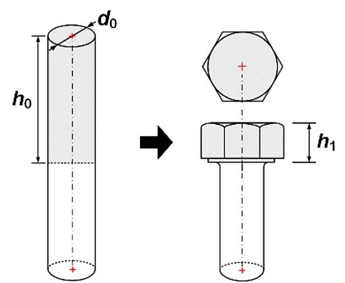
Definition of the initial diameter, initial head height, and upset head height of a hexagonal bolt
2.2 Process Limitations for Upset Forging
The upsetting operation is performed either in a single stage or in multiple stages, depending on the forming conditions. Process design is primarily governed by the need to prevent defects such as buckling and cracking, and the number of forming stages is determined accordingly. Upset forging is typically classified as closed-die or free forging based on the die configuration. In free forging, a trimming operation is required to achieve the final head geometry, thereby causing material loss in the form of chips. However, because the material undergoes relatively simple deformation, this process is advantageous in terms of forming stability and lower forging load. In contrast, closed-die forging enables the final shape to be produced in a single forming step, thereby improving production efficiency. Nevertheless, a sharp increase in forming load is typically observed when the material completely fills the die corners [14], [15]. Such high forming forces may lead to severe die damage, plastic deformation of the tooling, and accelerated tool wear; therefore, they must be carefully considered in process design [16]. For these reasons, a free forging process was adopted in the present study, considering the tool life and capacity limitations of the cold former.
In addition, two process limitations, including the upset ratio (s) and the upset strain (φ), were adopted to evaluate the risk of defect occurrence based on previous studies [17]–[19], which are expressed as follows:
| (1) |
| (2) |
where the upset ratio (s) is the ratio of the initial height (h0) to the initial diameter (d0) and is a key parameter governing the buckling behavior of the workpiece. Because this parameter is geometric in nature, it is independent of material properties and is therefore applicable to aluminum alloy bolt forming. The upset strain (φ), defined as the logarithmic strain based on the ratio h1/h0, where h1 denotes the upset head height, represents the degree of deformation and is used as an indicator of material formability. In general, when the upset ratio lies within the range of 1.6~2.1, the upsetting operation can be performed in a single stage. Based on the evaluation of these two process limitations, the risk of defects such as buckling and cracking was assessed. The results indicated that the required deformation exceeds the allowable limits for single-stage upsetting, and therefore, a multi-stage upset forging process was adopted.
2.3 Preform Design for Multi-Stage Forging Process
For multi-stage forming processes, the design of the intermediate shape, hereafter referred to as the preform, is critical because it strongly affects material flow during deformation and consequently influences the dimensional accuracy of the final product [21]. In the present study, the design rule proposed by Lange [19] was adopted to determine the preform geometry for the multi-stage forging process. Figure 2 illustrates the design rule, which considers major parameters such as the upset ratio, cone angle, guide length, and cone length. The preform geometry was determined by interpolating the calculated upset ratio within the applicable range of the design chart and by considering the volume relationship between the workpiece head portion and the punch cavity.
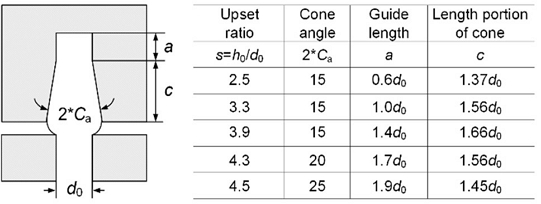
Schematic illustration of the preform geometry and design parameters
2.4 Feasibility of the Designed Multi-Stage Upsetting
After the intermediate shapes for the multi-stage upsetting process were determined, the number of forming stages was evaluated based on the process limitations described earlier in order to prevent defects such as buckling and cracking. In the present study, the process sequence was initially configured to consist of preforming, first upsetting, and second upsetting. When tapered dies are used in upsetting, an equivalent diameter must be defined to apply the process limitations, which are generally established for cylindrical geometries. Although the arithmetic mean of the entrance and bottom cavity diameters can be used as a simple approximation, this method does not adequately represent the actual deformation stability. Since buckling resistance is governed by the area moment of inertia of the cross-section, the equivalent diameter was determined based on the moment of inertia. Accordingly, the equivalent mean diameter (dm,i) was calculated from the arithmetic mean of the area moments of inertia at the two end sections of the tapered cavity as follows [21]:
| (3) |
where da and db denote the diameters at the entrance and bottom of the tapered die cavity, respectively (See Figure 5).
For the first upsetting stage, the initial geometry was assumed to be cylindrical, and the equivalent diameter was obtained based on the volume constancy condition. Table 1 summarizes the calculated process limitations for each stage. All calculated values fall within the allowable ranges, indicating that the proposed multi-stage upsetting design satisfies the feasibility criteria. Figure 3 presents the intermediate profiles for each stage of the designed multi-stage upsetting process. In the modified design, the initial head diameter was reduced from 10.7 mm to 10.58 mm. Accordingly, the initial head height was revised from 34.5 mm to 36 mm to satisfy the target volume.

Calculated process limitations for each stage of the multi-stage upsetting process
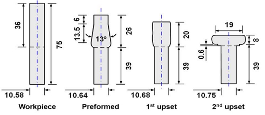
Profile at each stage of the multi-stage upset forging process
3. Forming Load Evaluation during Multi-Stage Upset Forging
3.1 Slab Method Analysis for Upset Forging
The slab method is a useful analytical approach for estimating forming loads in various metal forming processes. In particular, the forming load (L) for axisymmetric, homogeneous open-die upset forging can be expressed as follows (See Figure 4) [22]:
| (4) |
| (5) |
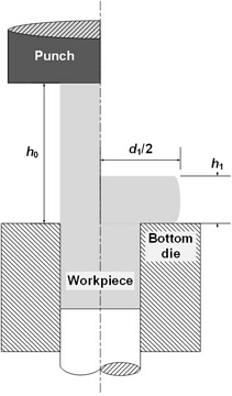
Schematic of axisymmetric homogeneous open-die upset forging for slab method
where d1 is the final diameter of the upset head, σf is the flow stress, m is the shear friction factor, h1 is the final upset head height, h0 is the initial height of the workpiece to be deformed, K is the strength coefficient, and n is the strain-hardening exponent.
It should be noted that the formulation above is only suitable for open-die upsetting and cannot be directly used to predict the forming load in semi-closed or closed-die upsetting processes, such as the preforming stage examined here. During preforming, material flow is constrained by the tapered die cavity, resulting in a smaller deforming volume than in open-die upsetting. Additionally, the final upset dies are more complex geometrically due to the tapered upper part and washer face. Therefore, this study employed the modified slab method [10], accounting for effective deformation, to estimate the forming load at each stage of the multi-stage cold upset forging process.
Figure 5 illustrates the preforming stage considered in the application of the modified slab method. The peak forming load is generated at the end of the upsetting stroke. At this stage, the head region can be divided into three distinct layers according to their deformation characteristics, as shown in Figure 5. The upper and middle layers (layers a and b) are in contact with the die wall and are therefore constrained, resulting in negligible additional deformation. These layers can thus be regarded as undergoing rigid-body motion. In contrast, the bottom layer (layer c) remains relatively unconstrained and continues to deform. Accordingly, for an accurate estimation of the forging load near the end of the stroke, the deformation of the bottom layer is considered as the primary contributor.
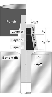
Application of modified slab method: preforming
In Equations (4) and (5), the geometrical parameters required for predicting the forming load are d1, h0, and h1. Since the forming load near the end of the stroke is primarily governed by the deformation of the bottom layer (layer c), these parameters should be modified to represent the geometry of this deforming region. Accordingly, Equations (4) and (5) are revised as follows:
| (6) |
| (7) |
where dm,c is the equivalent mean diameter of the layer c, hc is the final height of the layer c, and h0,c is the initial height of the layer c corresponding to the final height hc.
The values of dm,c and h0,c were determined based on the principle of volume constancy. By assuming that the bottom layer is equivalent to a cylinder with a diameter of dm,c, the corresponding initial height h0,c can be obtained using the following equations.
| (8) |
| (9) |
| (10) |
where hp, ha, and hb are the heights of the preform, layer a, and layer b, respectively. Vc is the volume of layer c, determined from the volume constancy condition as Vc = Vp – (Va + Vb) where Vp, Va, and Vb are the volumes of the preform, layer a, and layer b, respectively. Vb is calculated using the geometric formula for a truncated cone.
In the same manner as in the preforming stage, the forged head in the final upsetting stage (i.e., the second upsetting) is divided into three regions: the upper head part (layer u), the upsetting region (layer v), and the washer face region (layer w), as shown in Figure 6. At the end of the stroke, only the material in layer v undergoes plastic deformation, while the materials in layers u and w are constrained by the punch cavity and the washer face of the bottom die, respectively. The forging load can therefore be predicted using Equations (11) and (12) as follows:
| (11) |
| (12) |
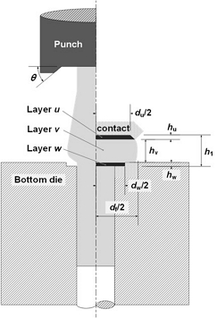
Application of modified slab method: second upsetting
where df is the diameter of final upset head, hv is the final height of upset part, is the mean effective strain by preforming.
The unknown parameters in the load prediction formula are the final head diameter df and the height of the upset region hv. The value of hv is determined using Equation (13). By applying the principle of volume constancy, a third-order equation with respect to df is obtained, as given in Equation (14). Substituting Equation (13) into Equation (14) yields the value of df as the root of the cubic equation. Finally, the forming load is calculated using Equations (11) and (12).
| (13) |
| (14) |
3.2 Validation of Forming Load Analytical Model
The effectiveness of the analytical model proposed in the previous section was verified via FEM analysis, which model was originally established in the previous author’s study [7]. The simulation was carried out using DEFORM, a commercial finite element software for metal forming analysis. Figure 7(a) illustrates a two-dimensional (2D) axisymmetric FEM model for the multi-stage upset forging process. The model consists of 5,054 elements and 5,340 nodes. The upsetting speed was set to 100 mm/s to reflect typical industrial operating conditions. The friction factor between the workpiece and the dies was set to be 0.1 [22]. The true stress () – true strain () relationship of the annealed aluminum alloy (Al6061-T0), obtained from a uniaxial tensile test, was expressed as follows:
| (15) |
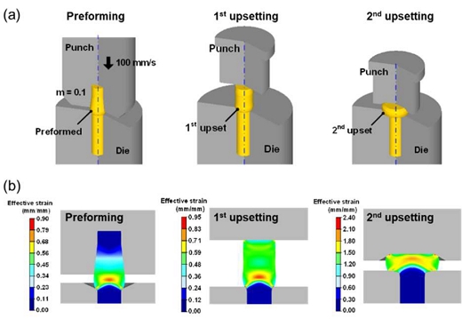
(a) FEM model for multi-stage upset forging, and (b) effective strain distributions obtained from the FEM analysis
Figure 7(b) illustrates the distribution of effective strain at each stage of the multi-stage upset forging process. During preforming, plastic deformation was mainly constrained in the lower part of the head, while the material flow in the upper part was heavily limited by the punch cavity's geometry. This supports the assumptions made during load estimation for this stage. In the first upsetting phase, deformation primarily occurred in the upper part of the head, which experienced minimal plastic strain during preforming. Conversely, the lower region, which had undergone work hardening earlier, showed limited additional deformation. In the second upsetting stage, a typical deformation pattern known as barreling was observed. This results from friction at the interface between the dies and the workpiece, which restricts radial flow near the contact surfaces while allowing greater lateral expansion in the center, leading to uneven deformation.
To validate the FEM model, upset forging experiments were conducted under process conditions identical to those used in the simulations. The experimental conditions are described in our previous study [7]. Figure 8 shows the forging dies used in the experiments, and Figure 9 compares the FEM results with the bolt head shapes obtained from the multi-stage forging process. The predicted head geometry and dimensions showed close agreement with those of the experimentally forged specimens. In addition, no defects such as buckling or surface cracking were observed in the formed bolt heads. These results confirm that the FEM model can accurately describe the deformation behavior and provides a reliable representation of the actual forging process.
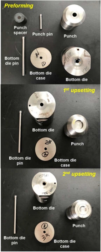
Dies used for the multi-stage upsetting experiments

Comparison of deformed shapes predicted by FEM analysis and those obtained from experiments
Based on the validated FEM model, forming loads during preforming and second upsetting were predicted and compared with results from the proposed analytical model. The forming loads predicted by FEM and the analytical method are shown in Figure 10. FEM analysis predicted forming loads of 3.73 tons for preforming and 13.87 tons for the second upsetting stage. According to the analytical model, the respective loads were 3.72 tons and 13.71 tons. The results from the slab method show good agreement with FEM predictions, with an error of approximately 1% relative to FEM results, indicating that the proposed analytical model can reasonably estimate forming loads in the multi-stage cold upsetting of aluminum alloy bolts. However, experimental measurements of the forming load were not feasible in the present study due to equipment limitations. Future work involving experimental load measurements is needed to further validate the proposed model.
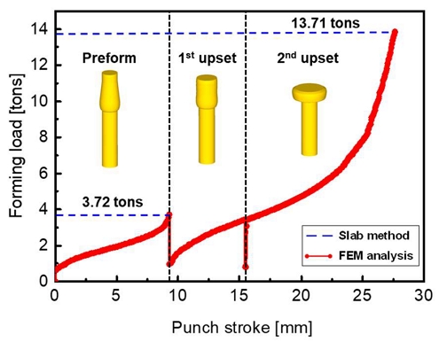
Comparison of forming loads predicted by the slab method and FEM analysis
4. Conclusion
This study designed a multi-stage cold upset forging process for an Al6061-T0 M12 hexagonal bolt, and proposed an analytical method based on the modified slab approach to predict the forming load. The effectiveness of the method was validated through FEM analysis and cold forming experiments. The main findings are summarized as follows:
- 1. A design procedure for the multi-stage cold upsetting process was proposed based on the volume constancy principle, upsetting design rules, and process limitations.
- 2. A modified slab method was utilized to estimate the forming load by taking into account the actual deforming volume near the end of the stroke, where material flow is constrained by the die cavity.
- 3. FEM simulations and upset forging experiments closely matched in the final head shape and dimensions. No defects, such as buckling or surface cracking, were observed, confirming the reliability of the FEM model.
The analytical model could estimate forming loads with about 1% error compared to FEM results, confirming its validity. This method provides a practical way to quickly predict forming loads and can be effectively applied in the process design of multi-stage cold forging of aluminum alloy bolts.
Acknowledgments
This research was supported by Korea Basic Science Institute (National Research Facilities and Equipment Center) grant funded by Ministry of Education (grant No.2022R1A6C1001B738).
Author Contributions
Conceptualization, S. C. Park and K. H. Lee; Methodology, S. C. Park and K. H. Lee; Software, S. C. Park; Validation, S. C. Park and K. H. Lee; Formal Analysis, S. C. Park and K. H. Lee; Investigation, S. C. Park; Writing—Original Draft Preparation, S. C. Park; Writing—Review & Editing, K. H. Lee; Visualization, S. C. Park; Supervision, K. H. Lee; Funding Acquisition, K. H. Lee.
References
-
L. H. Chiu, C. Y. Tsai, K. H. Chen, C. J. Hu, and H. Chang, “Effect of coarse second-phase particles on galvanic corrosion of anodized 6061 aluminum alloy coupled with C1100 copper,” International Journal of Electrochemical Science, vol. 10, no. 8, pp. 6572-6585, 2015.
[https://doi.org/10.1016/S1452-3981(23)06743-3]

-
S. J. Kim, S. K. Jang, M. S. Han, J. C. Park, J. Y. Jeong, and S. O. Chong, “Mechanical and electrochemical characteristics in seawater of 5052-O aluminum alloy for ship,” Transactions of Nonferrous Metals Society of China, vol. 23, no. 3, pp. 636-641, 2013.
[https://doi.org/10.1016/S1003-6326(13)62510-8]
-
J. Hirsch, “Recent development in aluminium for automotive applications,” Transactions of Nonferrous Metals Society of China, vol. 24, no. 7, pp. 1995-2002, 2014.
[https://doi.org/10.1016/S1003-6326(14)63305-7]
-
D. L. Zhang, W. Wang, and Y. Li, “An electrode array study of electrochemical inhomogeneity of zinc in zinc/steel couple during galvanic corrosion,” Corrosion Science, vol. 52, no. 4, pp. 1277-1284, 2010.
[https://doi.org/10.1016/j.corsci.2009.12.030]
-
B. Wang, J. Liu, M. Yin, Y. Xiao, X. H. Wang, and J. X. He, “Comparison of corrosion behavior of Al–Mn and Al–Mg alloys in chloride aqueous solution,” Materials and Corrosion, vol. 67, no. 1, pp. 51-59, 2016.
[https://doi.org/10.1002/maco.201408211]
-
H. Ye, X. Xu, Y. Zhang, L. Wang, and Y. Wang, “Visualization and simulation investigation of copper–nickel alloy and carbon steel galvanic corrosion in marine environment,” Journal of Electroanalytical Chemistry, vol. 953, p. 118013, 2024.
[https://doi.org/10.1016/j.jelechem.2023.118013]
-
S. C. Park, D. H. Lee, D. C. Ko, B. M. Kim, M. H. Kim, and K. H. Lee, “Integrated process design of Al6061 alloy bolts for fastening offshore platforms,” Journal of Mechanical Science and Technology, vol. 33, no. 8, pp. 3695-3707, 2019.
[https://doi.org/10.1007/s12206-019-0711-5]
-
S. C. Park and K. H. Lee, “Design of the trimming process of an Al6061 alloy bolt head using finite element analysis and the Taguchi method,” Journal of the Korean Society of Marine Engineering, vol. 42, no. 10, pp. 800-806, 2018.
[https://doi.org/10.5916/jkosme.2018.42.10.800]
-
S. C. Park, W. R. Dong, and K. H. Lee, “Design of a thread rolling process for manufacturing Al6061-T6 alloy bolt using FE analysis and the Taguchi method,” Journal of the Korean Society of Marine Engineering, vol. 42, no. 6, pp. 443-450, 2018 (in Korean).
[https://doi.org/10.5916/jkosme.2018.42.6.443]
-
M. O’Connell, B. Painter, G. Maul, and T. Altan, “Flashless closed-die upset forging-load estimation for optimal cold header selection,” Journal of Materials Processing Technology, vol. 59, no. 1-2, pp. 81-94, 1996.
[https://doi.org/10.1016/0924-0136(96)02289-3]
-
J. B. Rao, S. Kamaluddin, J. A. Rao, M. M. M. Sarcar, and N. R. M. R. Bhargava, “Deformation behavior of Al–4Cu–2Mg alloy during cold upset forging,” Journal of Alloys and Compounds, vol. 471, no. 1-2, pp. 128-136, 2009.
[https://doi.org/10.1016/j.jallcom.2008.04.020]
-
H. C. Lee, M. A. Saroosh, Y. T. Im, H. S. Kim, I. H. Son, and D. L. Lee, “Two-dimensional finite element approximation of the hexagonal bolt forming process,” Journal of Materials Processing Technology, vol. 201, no. 1-3, pp. 19-24, 2008.
[https://doi.org/10.1016/j.jmatprotec.2007.11.168]
-
S. H. Lin, D. C. Chen, U. C. Chai, and G. Y. Tzou, “FEM analysis and experimental validation on multi-pass forging of Torx round flange bolt,” International Journal of Automotive Technology, vol. 21, no. 5, pp. 1113-1119, 2020.
[https://doi.org/10.1007/s12239-020-0105-9]
-
J. S. Choi, S. Nawaz, S. K. Hwang, H. C. Lee, and Y. T. Im, “Forgeability of ultra-fine grained aluminum alloy for bolt forming,” International Journal of Mechanical Sciences, vol. 52, no. 10, pp. 1269-1276, 2010.
[https://doi.org/10.1016/j.ijmecsci.2010.06.002]
-
S. Chen, Y. Qin, J. G. Chen, and C. M. Choy, “A forging method for reducing process steps in the forming of automotive fasteners,” International Journal of Mechanical Sciences, vol. 137, pp. 1-14, 2018.
[https://doi.org/10.1016/j.ijmecsci.2017.12.045]
-
F. Wei and H. Lin, “Multi-objective optimization of process parameters for the helical gear precision forging by using Taguchi method,” Journal of Mechanical Science and Technology, vol. 25, no. 6, pp. 1519-1527, 2011.
[https://doi.org/10.1007/s12206-011-0430-z]
-
T. Altan, G. Ngaile, and G. Shen, Cold and Hot Forging: Fundamentals and Applications, ASM International, 2004.
[https://doi.org/10.31399/asm.tb.chffa.9781627083003]
- H. Tschaetsch, Metal Forming Practice, Springer, 2006, pp. 18-32.
- K. Lange, Handbook of Metal Forming, Society of Manufacturing Engineers, 1985.
-
J. J. Park and H. S. Hwang, “Preform design for precision forging of an asymmetric rib-web type component,” Journal of Materials Processing Technology, vol. 187-188, pp. 595-599, 2007.
[https://doi.org/10.1016/j.jmatprotec.2006.11.034]
-
M. I. Gokler, T. A. Dean, and W. A. Knight, “Computer-aided sequence design for hot upset forgings,” Proceedings of the Twenty-second International Machine Tool Design and Research Conference, pp. 457-466, 1982.
[https://doi.org/10.1007/978-1-349-06281-2_57]
- T. Altan, S. I. Oh, and H. L. Gegel, Metal Forming: Fundamentals and Applications, ASM International, 1983.