Velocity and temperature profiles of Al/water micro fluid in a circular tube with swirl
A lot study of convection heat transfer on internal flow has been extensively conducted in the past decades using of high specific surface area, increasing heat transfer coefficient, swirling flow and improving the transport properties. This study concerned with the application of a tangential slot swirl generator for improving heat transfer in a horizontal circular copper tube. The Al particles(about 100~130μm) was employed for this experimental work. 3D PIV(particle image velocimetry) technique has employed to measure velocity profiles of Al particles with and without swirl flow. The copper tube is heated uniformly by winding of a heating coil for heat transfer work, having a resistance of 9 ohm per meter. Experiments are performed in the Reynolds number range of 6,800~12,100 with swirl and without swirl using Al particles. Experimental data for comparison of Nusselt number is presented that of with swirl and without swirl along the test tube for the Reynolds numbers. The Nusselt number is improved with increasing of Reynolds numbers or swirl intensities along the test tube. The Nusselt number with swirl flow is about 60.0% to 119.0% higher than that obtained by the Dittus–Boelter equation.
Keywords:
Convection, Nusselt number, Swirl, PIV, Dittus-Boelter1. Introduction
The advantage of high heat flow processes has significantly increased the demand for new technologies that enhance heat transfer. For instance, microprocessors have become smaller and more powerful; as a result, the demand for heat flow has steadily increased over time, leading to new challenges in thermal management.
The characteristics of turbulent swirl flows have been studied extensively because the study of swirl flow is of great technological and scientific importance. Swirl flow improves the heat flow in pipes. Saidur et al. [1] recently reviewed the application of nanofluids and found that the thermal conductivity of nanofluids increases up to 150% with an increase in temperature. However, despite studies on this subject, the exact mechanism of enhanced heat transfer for nano fluids remains unclear. Numerous challenges must be identified and addressed to ensure the success of different applications. Ravikanth et al. [2] analyzed the influence of temperature and the concentration of nano fluids on the thermophysical properties of liquids and found that the addition of nano particles to any liquid significantly increases viscosity and moderately increases thermal conductivity. Specific heat and density also changes slightly. Zoubida et al. [3] studied the natural convective heat transfer of nano fluids and concluded that nanofluids enhance heat transfer and are highly suitable for various applications. Mohammed et al. [4] and Sohel et al. [5] studied forced convective heat transfer with fluid flow and boiling nano fluid. Mohammed et al. [4] also studied fluid flow and the heat transfer behavior of different types of single-phase fluid flow over a backward-facing step. The researchers found that the Nusselt number increases with the increase in velocity, Prandtl number, and aspect ratio. Sohel et al. [5] studied boiling heat transfer with nanofluids in carbon tubes and found that boiling heat flux can be enhanced depending on the concentration of the surfactants. Much attention has been provided recently to the study of swirl flow with energy problems. This research area is of practical importance given that swirl atomizers, dust extractors, and applications that involve enhanced heat transfer coefficients are widely utilized. Govarthan et al. [6] conducted a CFD simulation of the heat transfer of nano fluids in a circular tube fitted with twisted inserts in a swirling flow under constant heat flux. The results were explained with Fluent version 6.326 in laminar flow. Heat transfer increased with Reynolds number and decreased with twist ratio at the maximum value of 2.93 for twist ratio. Adrian et al. [7] utilized numerical and experimental methods to study a micro fluid channel consisting of two T junctions with vibration. Svetlana et al. [8] employed twisted tape as a turbulence promoter in the micro filtration of milk. The use of the twisted tape reduced both reversible and irreversible fouling and significantly increased the permeate fluxes. Syam et al. [9] also utilized twisted tape to measure the heat transfer and friction factor of an Al2O3 nano fluid in circular tubes. The heat transfer coefficient and friction factor at 0.5% volume concentration of Al2O3 in the nanofluid were 33.51% and 1.096 times higher, respectively, compared with the values obtained from flowing water in a tube.
An Al/water micro fluid was utilized in this study to measure velocity profiles through 3D particle image velocimetry (3D-PIV). The Nusselt numbers were calculated with and without swirl flows in a horizontal circular copper tube. Therefore it will be contributed for a design of heat exchanger.
2. Experimental Apparatus
2.1 Velocity measurement
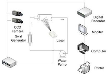
A stereoscopic PIV system in Figure 1 is employed to measure the velocity of the Al/water micro fluid. A transparent tube with 13.8mm diameter and 1,000mm length is utilized for the PIV measurement. The camera calibration method utilized for the 3D-PIV measurement is based on the method utilized by Doh et al. [10]. This method involves quantitative measurements in the calculation of the camera parameters. A square box is installed outside the test tube to further reduce the distortion effect. Each experimental image is subjected to 2D image transformation. The original images are warped prior to calibration.
2.2 The test tube
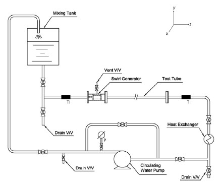
Figure 2 and Figure 3 present the schematic of the experimental test tubes for heat transfer. The test tubes are manufactured through a copper tube with a diameter of 13.8mm, length of 1,000mm, and thickness of 1.0mm. The walls of the test tubes are uniformly heated by electrical power of 0.36kW (120voltage×3Amp). The heating coil is uniformly wound at 10.0mm distance along the test tube. A voltage regulator is employed to adjust the heat flux. K-type thermocouples and the 32-channel LabView system are employed to measure bulk and wall temperatures. Two flanges are placed at the end of each test tube to prevent loss of electric power. A water pump with rpm control and 1,600cc per minute pumping capacity is utilized to circulate the micro fluid in the system. Mass flow is measured at the pump exhaust port by using a weighter. To calculate Re number, the mean velocities were employed from PIV results and the mass flow at the outlet of the pump, and then refer to "Equation (1)" and "Equation (2)" for viscosity. But the velocities are not much different each other, such as the velocity from the PIV results and the velocity from the mass flow. The Al particles are dispersed by pouring some distilled water into the mixing water tank. Producing swirling flow, a tangential slot type swirl generator were used for this work.
2.3 Evolution of the thermophysical properties of the micro fluid
The Al micro particles (approximately 100μm to 130μm) are supplied by a Korean company. Distilled water is utilized to disperse the Al particles with 0.25% volume concentration. The properties of the micro fluid, such as viscosity, specific heat, and thermal conductivity, are measured with different kinds of measuring equipment. The equations below are utilized to calculate the aforementioned properties. The density of the micro fluid is derived by "Equation (1)".
The Einstein equation provided below is adopted to determine the viscosity of the micro fluid.
where, μf is the viscosity of the base liquid and φ is the volume fraction of the micro fluid (0.25%). The following equation proposed by Hamilton et al. [16] is utilized to calculate thermal conductivity:
where, Knf, Kbf, and K9 are the thermal conductivity of the micro fluid, base fluids, and micro particles, respectively. n is the space factor of the micro fluid, and 3 refers to the spherical micro fluid. The more accurate equation provided by Buongiorno is presented below [12].
3. Results and Discussion
3.1 Velocities profiles
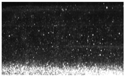
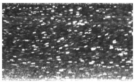
Figure 4 shows the raw images of the Al particles without swirl along the test tube. Some particles settle on the inside of the bottom of the test tube without swirling flow at Re=1,110. This occurrence is caused by the density of the Al particles. Figure 5 shows that the particles move at a certain flow angle at a swirling flow of Re=1,870. A few particles remain deposited on the bottom of the test tube. This occurrence is caused by the tangential velocity of the swirling flow with a low Reynolds number.
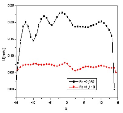
Figure 6 presents the axial velocity without swirl flow for Re=1,110 and Re=2,987. The velocity appears distorted at the left side of the tube it is clearly affected by the particles at the bottom.
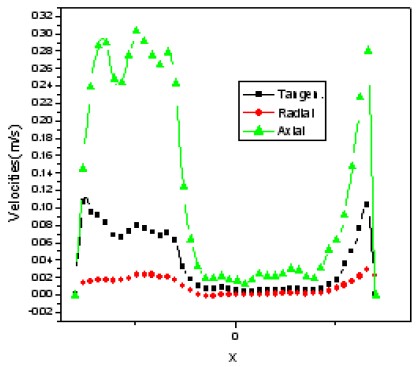
Figure 7 shows the three velocities with swirling flow along the test tube. The axial velocity swings to the left side of the test tube, suddenly decreases near the centerline of the test tube, and then sharply increases. These reactions are associated with the tangential velocity of the swirling flow and deposited particles at the bottom of the test tube. These velocities exhibit a slightly normal swirling flow at a high Reynolds number, with the axial velocity showing positive results near the wall of the test tube and steeply decreasing at the centerline of the test tube. The radial velocity is very low across the test tube. Tangential velocity is low and very similar to axial velocity. The velocity near the wall increases sharply, suddenly decreases to zero at the centerline, and then increases again similar to the tangential velocity. These profiles are very similar to that of the normal swirling flow.
3.2 Heat transfer results
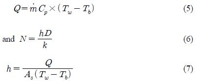
Uniform heat flux(0.36kW×220V) was employed for the heat transfer experiment. The wall and fluid temperatures along the test tube were measured using k-type thermocouples. The bulk temperatures and Nusselt numbers were calculated with and without swirl flow through the following equations:
where, As and Tw indicate the surface area and wall temperature, h is the heat transfer coefficient, respectively. "Equation (6)" is the Dittus–Boelter equation [13], which yielded the following result:
Nu is the Nusselt number, and Re and Pr are the Reynolds and Prantl numbers, respectively.
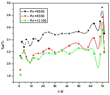
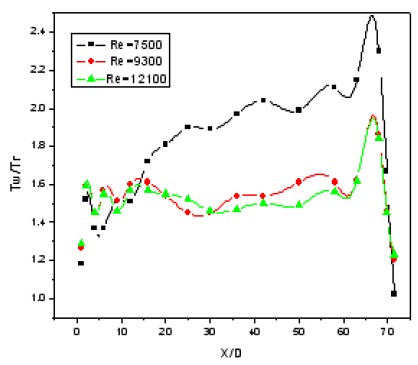
Figure 8 shows the comparison of the Tw/Tr temperatures without swirl for Re=6,800 to 12,100 where Tw and Tr indicate wall temperature and room temperature, respectively. These temperatures increase sharply at the entry of the test tube. The temperature profiles increase with the increase in heat flux and decrease suddenly at the end of the test tube because of the lack of heat flux and presence of heat loss. The temperature profiles decrease as the Reynolds numbers increase.
Figure 9 presents the Tw/Tr temperatures of the test tube with swirl flow of Re=6,800 to 12,100. The profiles are similar to those without swirl flow, but the temperature profiles are 1.25 to 1.37 times lower than that of the test tube without swirl flow. These results indicate that much energy is transferred to the micro fluid from the heated wall through the Al particles and swirling flow, causing the wall temperature to become lower than that of the test tube without swirl flow.
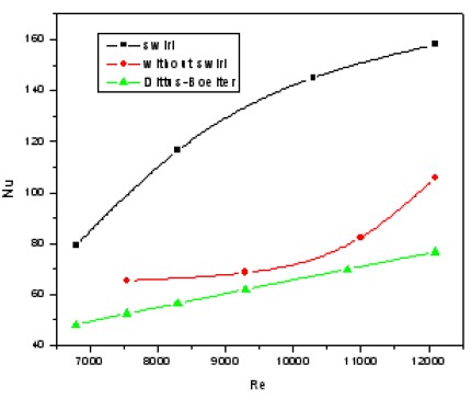
Figure 10 shows the comparison of the Nusselt number with and without swirl and the result obtained by the Dittus–Boelter equation. The Nusselt number without swirl is approximately 20.0% to 37.5% higher than that obtained by the Dittus–Boelter equation.
The difference is attributed to the particles of the Al/water micro fluid. The Nusselt number with swirl is also about 60.0% to 119.0% higher than that obtained by the Dittus–Boelter equation. The difference is attributed to the tangential velocity of the swirling flow and Al particles.
4. Conclusion
An Al/water micro fluid was employed in this study. Velocity profiles and wall temperatures (Tw/Tr) were measured through the PIV technique. K-type thermocouples were placed along the test tube for uniform heating. Nusselt numbers with and without swirl flow in a horizontal circular tube were calculated for Re=6,800 to 12,100. The following conclusions were obtained:
1) The axial velocities without swirl flow for Re=1,110 and Re=2,987 were presented. The velocities are distorted at the left side of the tube, which is due to the particles at the bottom affecting the velocities.
2) With regard to swirling flow, the axial velocity swings to the left side of the test tube, suddenly decreases near the centerline of the test tube, and then sharply increases. These results are associated with the tangential velocity of the swirling flow and deposited particles at the bottom of the test tube.
3) The wall temperature with swirl flow is 25.0% to 37.5% higher than that without swirl flow. Both temperatures decrease as the Reynolds number increases. These results are ascribed to the constant heat flux and the fact that much energy is transferred by the particles along the test tube.
4) The Nusselt number without swirl flow is approximately 10.0% to 24.5% higher than that obtained by the Dittus–Boelter equation. The Nusselt number with swirl flow is about 60.0% to 119.0% higher than that obtained by the Dittus–Boelter equation. This result is ascribed to the tangential velocity of the swirling flow.
Acknowledgments
This research was supported by the ReSEAT program funded by the Ministry of Science, ICT and Future Planning through the National Research Foundation of Korea and the Korea Lottery Commission grants.
References
-
R. Saidur, K. Y. Leong, and H. A. Mohammad, “A review on applications and challenges of nano fluids”, Renewable and Sustainable Energy Review, 15(3), p1646-1668, (2011).
[https://doi.org/10.1016/j.rser.2010.11.035]

-
Ravikanth, S. Vajjha, and Das, Debendra K., “A review and analysis on influence of temperature and concentration of an fluids on thermophysical properties”, Heat Transfer and Pumping Power, International journal of heat and mass transfer, (2012), 55(15-16), p4063-4078.
[https://doi.org/10.1016/j.ijheatmasstransfer.2012.03.048]

-
Haddad, Zoubida, Hakan F. Oztop, Eiyad Abu-Nada, and Amina Mataoui, “A review on natural convective heat transfer of nano fluids”, Renewable and Sustainable Energy Review, (2012), 16(7), p5363-5378.
[https://doi.org/10.1016/j.rser.2012.04.003]

-
H. A. Mohammed, A. A. Al-aswadi, N. H. Shuaib, and R. Saidur, “Convective heat transfer and fluid flow over a step using nano fluids”, Renewable and Sustainable Energy Review, 15, p2921-2939, (2011).
[https://doi.org/10.1016/j.rser.2011.02.019]

-
S. M. Sohel Murshed, C. A. Nieto de Castro, M. J. V. Lourenco, M. L. M. Lopes, and F. J. V. Santos, “A review of boiling and convective heat transfer with nanofluids”, Renewable and Sustainable Energy Review, 15(5), p2342-2354, (2011).
[https://doi.org/10.1016/j.rser.2011.02.016]

-
Govarthan Pathipakka, and P. Sivashanmugam, “Heat transfer behavior of nano fluids in a uniformly heated circular tube fitted with herical inserts in laminar flow”, Superlattices Microstructures, 47, p349-360, (2010).
[https://doi.org/10.1016/j.spmi.2009.12.008]

-
Adrian, Neild, Tuck Wah, Ng, Gregory, J., Matthew Powers Sheard, and Oberti Stefano, “Swirl mixing at micro fluidic junctions due to low frequency side channel fluidic perturbations”, Sensors and Actuators B, 150(2), p811-818, (2010).
[https://doi.org/10.1016/j.snb.2010.08.027]

-
Svetlana Popovic, and Miodrag N. Tekic, “Twisted tapes as turbulence promoters in the microfiltration of milk”, Journal Membrane Science, 384(1-2), p97-106, (2011).
[https://doi.org/10.1016/j.memsci.2011.09.016]

-
L. Syam Sundar, and K. V. Sharma, “Turbulent heat transfer and friction factor of Al2O3 nano fluid in circular tube with twisted tape inserts”, Journal of Heat and Mass Trasfer, 53, p1409-1416, (2010).
[https://doi.org/10.1016/j.ijheatmasstransfer.2009.12.016]

- Yunus A. Cengel, Heat Transfer, McGrawHill, 2 ed, p441, (2003).
- F. J. Wasp, Solid-liquid Flow Slurry Pipeline Transportation, Trans, Tech, Publication, (1977).
-
R. S. Vajjha, D. K Das, and B. M. Mahagaonkar, “Density measurements of different nano fluids and their comparison with theory”, Petro, Sci. Tech, 27(6), p612-624, (2009).
[https://doi.org/10.1080/10916460701857714]

-
B. C. Pak, and Y. J. Cho, “Hydrodynamic and heat transfer study of dispersed fluids with submicron metallic oxide particles”, Experimental Heat Transfer, 11(2), p151-170, (1998).
[https://doi.org/10.1080/08916159808946559]

-
B. C Sahoo, R. S. Vajjha, R. Ganguli, G. A. Chukwu, and D. K. Das, “Determination of rheological behaviour of aluminium oxides and development of new viscosity correlations”, Petro. Sci. Tech, 27(15), p1757-1770, (2009).
[https://doi.org/10.1080/10916460802640241]

- J. Buongiorno, “Convective transport in nano fluids”, Journal of Heat and Mass Transfer, 128, p240-250, (2006).
-
R. L. Hamilton, and O. K. Crosser, “Thermal conductivity of heterogeneous two component system, I and EC”, Industrial & Engineering Chemistry Fundamentals, 1(3), p187-191, (1962).
[https://doi.org/10.1021/i160003a005]

