FMEA and QFD-based reliability evaluation of pressure sensors and transmitters for liquefied hydrogen storage systems in ships

Copyright © The Korean Society of Marine Engineering
This is an Open Access article distributed under the terms of the Creative Commons Attribution Non-Commercial License (http://creativecommons.org/licenses/by-nc/3.0), which permits unrestricted non-commercial use, distribution, and reproduction in any medium, provided the original work is properly cited.
Abstract
As part of the global transition toward carbon-free marine fuels to meet IMO 2050 targets, liquefied hydrogen has emerged as a promising alternative. However, its cryogenic storage conditions requirements and explosion risks necessitate highly reliable pressure monitoring devices. This study applies failure modes and effects analysis (FMEA) to evaluate the reliability of pressure sensors and transmitters used in hydrogen-storage ship systems, which are exposed to extreme environments such as cryogenic temperatures, high pressure, humidity, and electromagnetic interference. Failure modes were identified through expert analysis of smart and cylindrical sensor structures. Severity, occurrence, and detection scores were assigned to each failure mode, and the risk priority numbers (RPNs) were calculated. High-risk failures were concentrated in signal processing and transmission components. To support design decisions, we also performed a quality function deployment (QFD) analysis. The critical user and certification requirements were linked to technical responses and environmental test conditions. Humidity, lifetime, and low-temperature resistance were identified as key factors. The combination of FMEA and QFD enables efficient resource allocation and helps prioritize design improvements, contributing to enhanced sensor reliability for application in hydrogen-based marine environments.
Keywords:
Pressure transmitter, FMEA, QFD, RPN, Liquefied hydrogen1. Introduction
Under the International Maritime Organization (IMO)’s greenhouse gas (GHG) reduction strategy, the international shipping sector must reduce its GHG emissions by at least 20% by 2030 and at least 70% by 2040 compared with the 2008 levels, with the ultimate goal of achieving net-zero emissions no later than 2050 [1]. In response to this tightening global regulation and growing demands for improved marine atmospheric conditions, the transition from conventional fossil fuel-powered vessels to LNG-fueled ships has been accelerating [2][3]. However, LNG serves only as a transitional fuel that offers short-term GHG emission reductions compared with conventional fuels, and a complete shift to carbon-free fuels is essential to meet the IMO 2050 targets [4]-[6]. Consequently, next-generation carbon-free fuels such as ammonia and hydrogen have emerged as key alternatives.
Because of the inherent physical properties of ammonia and hydrogen, such as the toxicity and low flammability of the former and the high flammability and explosion risk of the latter, these next generation fuels require significantly higher levels of safety and technical reliability in their storage and handling processes than those implemented in conventional fuels [7][8]. In particular, ships have strict spatial constraints, making gaseous fuel storage inefficient owing to low volumetric energy density. Consequently, liquid-state storage is required to improve space efficiency. In the case of hydrogen, storage and transfer must occur at cryogenic temperatures of −253 °C. Furthermore, because hydrogen poses a severe explosion hazard in the event of leakage, highly reliable monitoring devices that can operate stably under extreme conditions are essential for onboard storage systems.
Monitoring systems incorporate a range of sensors that detect and transmit various physical properties such as pressure, temperature, flow rate, level, and viscosity in real time to ensure safe storage and transfer of fuel [9]-[11]. Among these, pressure sensors and transmitters are critical components as they continuously monitor the internal pressure of storage tanks and supply lines, allowing for early detection of abnormalities such as leakage, overpressure, and blockage.
However, conventional pressure sensors developed for existing fuels are not designed to withstand the cryogenic temperatures and hydrogen embrittlement encountered in liquid hydrogen environments. Therefore, systematic failure analysis and corresponding design improvements are required to ensure sensor reliability under such extreme conditions.
To systematically analyze the major failure modes and their effects on the pressure sensors used within liquid hydrogen fuel storage and transfer systems onboard ships, we performed failure modes and effects analysis (FMEA). In addition, a quality function deployment (QFD) approach was used to identify and prioritize customer requirements and the corresponding test conditions for the development of high-reliability pressure sensors.
FMEA is a structured risk assessment method that evaluates the probability of failure, severity of consequences, and difficulty of detection for individual components. It has been extensively utilized in the aerospace and automotive industries [12]-[14]. QFD serves as a strategic tool that incorporate customer needs into product design and development and has been widely adopted at the initial stages of product planning across various sectors [15]-[17].
In this study, FMEA was applied to pressure sensors that monitor pressure during the fuel storage and transfer process, and various failure modes that may occur in the liquid hydrogen tank environment were classified. Improvement strategies were proposed for high-risk items based on critical analysis. Subsequently, a QFD analysis was performed to prioritize the environmental test items required for the development of pressure sensors and transmitters for liquid hydrogen storage systems. Through these analyses, this study aims to establish a development direction for high-reliability pressure sensors and transmitters that can operate stably in cryogenic liquid hydrogen environments, thereby contributing to safety enhancement in hydrogen-fueled and storage ships.
2. Methodology for FMEA and QFD
2.1 FMEA Methodology
FMEA is a structured reliability evaluation technique that systematically identifies all potential failure modes that may occur during the design and operation of a system or equipment. It evaluates the effects of each failure on the overall system and establishes preventive measures based on the findings [13][14].
Figure 1 shows a flowchart outlining the FMEA process used in this study. The procedure begins by clearly identifying the functional units that constitute the target system. Since most systems consist of multiple subsystems and components, it is essential to define an appropriate level of decomposition that aligns with the analysis objective. This level must correspond to the degree at which the identified improvements can be practically applied. Once the functional units are determined, the potential failure modes that may occur when each function fails are estimated. The effects of each failure on the entire system or related higher and lower levels are then determined. The causes of failure under various conditions, such as mechanical damage, thermal effects, cyclic loading, wear, and lubrication problems, are further identified [18][19].

Flowchart of FMEA
The next step involves evaluating three parameters, namely severity (S), occurrence (O), and detection (D), each rated on a ten-point scale. The risk priority number (RPN) is then calculated as the product of these values using the equation RPN = S × O × D. The RPN does not represent the absolute risk of a failure mode but serves as a comparative index to assess relative risks within the same system or analytical scope. This approach makes it possible to prioritize failure modes with severe consequences despite low likelihood, or those that occur frequently but are difficult to detect [12]. In particular, recent studies in the field of marine engineering have demonstrated the applicability of FMEA for complex ship systems, including autonomous engine rooms [20]. Building on this framework, the present study performed FMEA for pressure sensors and transmitters used in liquid hydrogen storage systems to identify critical failure modes and guide design improvements.
2.2 Functional Analysis
In ships, pressure sensors and transmitters serve as essential components for maintaining the safety and operational efficiency of fuel systems by continuously monitoring the pressure of gases, liquids, or the internal environment of storage tanks and providing real-time data [21]. Pressure sensors detect physical pressure and convert it to an electrical signal, whereas transmitters process this signal into usable data for the control system. This information plays a vital role in managing fuel flow within storage tanks, pipelines, and supply lines, as well as in identifying abnormal conditions at an early stage [22][23].
In particular, the reliability and durability of pressure sensors and transmitters become even more crucial in cryogenic environments, such as those associated with liquid hydrogen storage systems. These environments frequently induce phase transitions between the gaseous and liquid states of the fuel, and the resulting pressure fluctuations can directly impact system stability [24]. Therefore, pressure measurement devices used under cryogenic conditions must exhibit high reliability and operate accurately and consistently even under thermal stress and external disturbances.
Pressure sensors can be classified into various types based on their operating principles; however, this study focused on two sensor and transmitter types commonly used in marine storage systems. Figure 2 shows the representative structure of the smart sensor type [25], whereas Figure 3 shows the cylindrical sensor type [26]. The functional analyses of each type are summarized in Tables 1 and 2. The smart sensor features an integrated digital display, allowing on-site users to directly view measured pressure values and conveniently adjust settings or check system status. In contrast, the cylindrical sensor is a simplified model without a display. It transmits the measured pressure data to a control system via a transmitter and is primarily used for remote monitoring.

Structure of the smart sensor

Structure of the cylindrical sensor

Functional analysis of the smart sensor
Functional analysis of the cylindrical sensor
2.3 QFD Methodology
QFD is an effective tool for enhancing design quality and reducing late-stage development costs by systematically translating customer requirements into technical specifications at the early stages of product design [16]-[17]. By converting the customer-specified needs to a form interpretable by designers and developers, QFD facilitates product development that maximizes customer satisfaction at the initial phase. This makes it particularly suitable for systems such as high reliability sensors where the operating environments are extreme and potential failures can be critical.
In this study, QFD was applied to pressure sensors and transmitters intended for use in liquid hydrogen storage environments. A total of eight customer and certification body requirements were selected, namely accuracy, maximum pressure capacity, high reliability, low temperature resistance, moisture resistance, vibra-tion resistance, electromagnetic compatibility, and pressure con-tainment. Additionally, nine environmental test items were select-ed for evaluation, namely high temperature, low temperature, vibration, humidity, thermal cycling, pressure, dielectric voltage and current, electromagnetic interference, and service life. These requirements were derived through literature review, analysis of relevant classification society standards, examination of existing commercial product specifications, and interviews with operators of cryogenic fuel systems [27]-[33]. The selection process also reflected the environmental and operational characteristics specif-ic to shipboard applications and liquid hydrogen systems.
QFD provides a visual representation of the priority relation-ships between user needs and the corresponding test items or design requirements, offering meaningful support in establishing development strategies beyond a simple listing of functions. In particular, the performance of pressure sensors and transmitters in liquid hydrogen systems is directly affected by variations in temperature and pressure. Therefore, prioritizing relevant envi-ronmental test items is a key factor in ensuring product reliability. These devices must endure high pressure and low temperature conditions, as well as combined stresses such as vibration, mois-ture, and electromagnetic interference over extended periods. Incorporating these considerations into the design process through QFD is essential.
The QFD performed in this study established a foundation for achieving high reliability design at the early development stage by analyzing customer requirements and evaluating the relative im-portance of environmental test items based on their correlation with design input elements. It is expected that the results of this QFD analysis can be applied throughout the full development cycle of sensors for liquid hydrogen-fueled ships, including technical specification definition, performance certification plan-ning, and test evaluation strategy formulation.
2.4 Evaluation Criteria for FMEA and QFD
In this study, FMEA was performed on pressure sensors and transmitters used in liquid hydrogen storage and supply systems, focusing on the failure modes that may occur during ship operation and in cryogenic environments. Although the typical risk evaluation criteria in FMEA consist of severity, occurrence, and detection rated on a ten-point scale, the detection score was excluded in this study as faults in pressure transmitters are generally highly detectable. The evaluation criteria, excluding detection, were reestablished with reference to MIL-STD-882D and existing FMEA-related literature [18][19][34][35], as presented in Tables 3 and 4.
Evaluation criteria of severity
Evaluation criteria of occurrence
The FMEA evaluation items consisted of severity and occur-rence, each classified into three levels. The combination of these two items was divided into a total of five levels as shown in Figure 4, with scores converted to 1, 3, 5, 7, and 9 points. The scor-ing system was categorized according to risk levels, where 9 points indicated intolerable, 3 to 7 points indicated As Low As Reasonably Practicable (ALARP), and 1 point indicated broadly acceptable.

Risk matrix table
Severity was evaluated based on the impact of a failure on sys-tem safety and operational stability. Occurrence was assessed by comprehensively considering the actual failure frequency, struc-tural reliability, and environmental durability in ship operation and cryogenic conditions. To this end, failure history data from a total of 12 vessels equipped with LNG cargo or fuel systems were examined. Expert evaluation was then carried out by a panel consisting of three field professionals with over ten years of experience in the design, manufacturing, and production of pres-sure sensors and transmitters.
Meanwhile, QFD was used to link the user and certification body requirements of pressure sensors with test items and tech-nical specifications. The evaluation was performed in two stages. In the first stage, the importance scores were calculated by evalu-ating each failure mode against major customer requirements. A total of eight requirements were selected, namely accuracy, max-imum measurable pressure, high reliability, low temperature re-sistance, moisture resistance, vibration resistance, electromagnetic compatibility, and pressure containment capability.
In the second stage, test items associated with each failure mode were evaluated, and the importance scores derived from the first stage were used as weights to calculate the total scores of each test item. Nine test items were selected, namely high temper-ature, low temperature, vibration, humidity, thermal cycling, pres-sure, dielectric voltage and current, electromagnetic interference, and service life. The same expert panel as in the FMEA evalua-tion performed the assessment using a four-level scoring system: 9 points (very important), 5 points (important), 3 points (moder-ate), and 0 points (irrelevant).
The QFD results contributed to the efficient allocation of re-sources and the selection of key performance factors during product design and test strategy planning. Furthermore, they were combined with FMEA results to establish the improvement directions for high-risk design elements.
3. Results and Discussion
3.1 FMEA Results
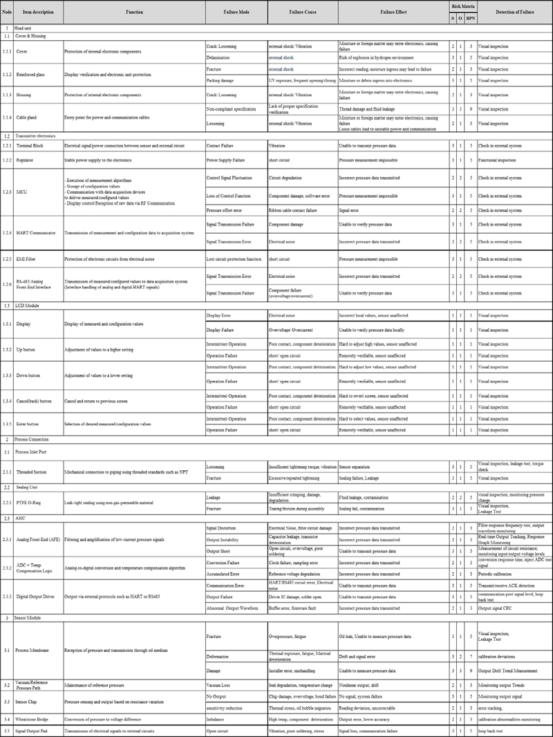
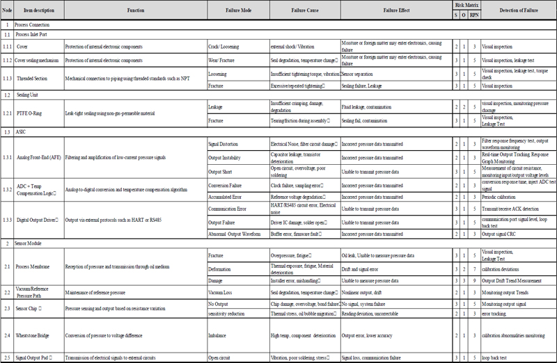
A total of 47 and 22 failure modes were identified in the Smart Sensor and Cylindrical Sensor, respectively based on the FMEA results, both of which are applied to the pressure sensors and transmitters used in liquid hydrogen storage systems on ships. The detailed failure modes are shown in Tables 5 and 6.
FMEA result of the smart sensor
FMEA result of the cylindrical sensor
The failure modes categorized as intolerable included the use of non-standard cable glands in the Smart Sensor, which may cause leakage, and structural damage to the process membrane. In the Cylindrical Sensor, one case of damage to the process mem-brane was included in this category. These failures may lead to critical functional losses such as failure to measure pressure or leakage. Notably, most of these cases were attributed to human errors such as assembly mistakes or failure to use standard parts.
These results were used to establish preventive measures and design improvements for the intolerable failure modes, as sum-marized in Table 7. These include actions such as familiarization with installation guidelines and standardization of components. The second-round RPN analysis results that reflect these coun-termeasures are also presented.
Intolerable failure modes and RPN reduction through design recommendation
The identified failure modes and corresponding risk assess-ment results can be used as a basis for establishing design im-provements and preventive maintenance strategies aimed at enhancing the reliability of sensors and ensuring operational safety under cryogenic and vibration conditions typical of liquid hydrogen environments. In particular, for high-risk failure modes, linkage with the QFD analysis allows for the identification of test items that require focused management, supplementation of environmental test conditions, and establishment of monitoring and diagnostic strategies to enable early detection and enhance sensor performance.
3.2 QFD Result
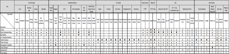
Table 8 depicts the results of the first phase of the QFD anal-ysis, whereas Table 9 shows those of the second phase. The Cylindrical Sensor was evaluated using the same procedure. However, since most of its components overlapped and the results were similar, it was omitted in this study. In the first phase (Level 1), importance scores were calculated based on the correlation between eight key requirements, namely accuracy, pressure measurement range, high reliability, low temperature resistance, humidity resistance, vibration resistance, electromagnetic compatibility, and pressure resistance, and each identified failure mode. The results showed that electronic components responsible for signal processing and data transmission, such as the signal output pad of the sensor module, ASIC, and transmitter electronics, had the highest importance scores. This indicates that these compo-nents are critical to achieving output accuracy and system reliability.
QFD result of the smart sensor (Level 1)
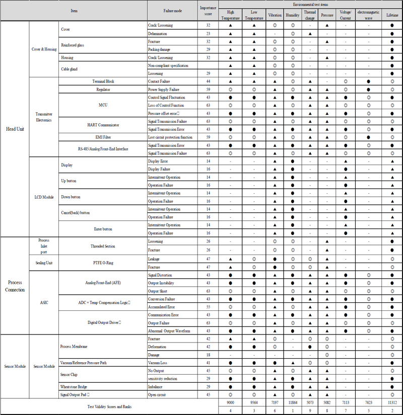
QFD result of the smart sensor (Level 2)
In the second phase (Level 2), the environmental test items as-sociated with each failure mode were identified. The importance scores obtained in the first phase were applied as weights to calculate the total scores for each test item. Among the nine test categories, namely high temperature, low temperature, vibration, humidity, thermal change, pressure, voltage/current, electromagnetic wave, and lifetime, humidity test had the highest total score. This reflects the inherent vulnerability of sensor products, which are directly exposed to external environments, to performance degradation or malfunction due to moisture ingress. This was followed by lifetime and low temperature, both of which also exhibited high importance scores, highlighting the need to ensure long term stability and reliability under cryogenic conditions.
These QFD results provide a rational basis for setting priorities among performance requirements and allocating development resources during the product design and testing strategy phase. Furthermore, when combined with the FMEA results, they provide guidance for establishing improvement strategies for design elements with high levels of risk.
4. Conclusion
This study applied the FMEA and QFD methods to pressure sensors and transmitters used in liquid hydrogen storage and supply systems to identify major failure modes, which contributes to the establishment of design and testing strategies. In particular, the correlations between potential failures in each sensor component and key performance requirements were analyzed considering extreme operating conditions such as cryogenic envi-ronments, high vibration, and electromagnetic interference.
The FMEA covered more than 30 detailed components, including the sensor module, ASIC, analog and digital electronic circuits, display, and input and output terminals. A total of 47 failure modes were identified, evaluated for severity and occurrence, and categorized into three levels, namely intolerable, As Low As Reasonably Practicable (ALARP), and broadly acceptable. Among the total failure modes, two in the smart sensor and one in the cylindrical sensor were classified as intolerable. These were attributed to human factors such as the use of nonstandard cable glands and structural damage to the process membrane due to handling errors or improper assembly by workers. Risk reduction was achieved through countermeasures such as worker train-ing and adherence to installation procedures.
A QFD analysis was also performed to evaluate technical importance based on the correlation between eight key user and certification authority requirements and nine environmental test items. In the first stage of the QFD, the signal processing and transmission circuits, such as the Signal Output Pad, ASIC, and Transmitter Electronics, in the sensor module had the highest importance. This result suggests that failure in these components may cause complete system shutdown or output errors. In the second stage, humidity, lifetime, and low temperature were identi-fied as the most critical environmental test conditions. This find-ing reflects the impact of condensation caused by repeated cool-ing and heating cycles and moisture infiltration under cryogenic conditions on the product’s lifetime and signal stability.
These results provide practical support in prioritizing technical responses within limited development resources for pressure sensor design and testing strategy. Moreover, the key failure modes and response priorities derived in this study can be used as foundational data for establishing prognostics and health management systems in autonomous ships or high-risk fuel systems. When linked with operational failure rate feedback, Bayesian reliability assessment models, and lifetime prediction models, these insights can be used to establish quantitative reliability assurance and optimized lifecycle strategies.
In our future work, experimental validation of the prioritized environmental test conditions will be performed to enhance design completeness. In addition, sensitivity analysis of early diagnostic parameters for sensor failure will be performed to enhance the development of high-performance pressure sensors with long term reliability in extreme environments.
Acknowledgments
This work was supported by a grant from the National R&D project of “Development of sensors for measuring temperature, flow and pressure(RS-2024-00437086)” funded by Ministry of Trade, Industry and Energy, South Korea. All supports are gratefully acknowledged.
Author Contributions
Conceptualization, Y. G. Kim; Methodology, Y. G. Kim; Software, J.M. Lee; Formal Analysis, J.M. Lee; Investigation, J.M. Lee; Resources, Y. G. Kim; Data Curation J.M. Lee; Writing-Original Draft Preparation, Y. G. Kim; Writing-Review & Editing, J.M. Lee; Visualization, J.M. Lee; Supervision, Y. G. Kim; Project Administration, Y. G. Kim; Funding Acquisition, Y. G. Kim.
References
- International Maritime Organization (IMO), 2023 IMO Strategy on Reduction of GHG Emissions from Ships, Resolution MEPC.377(80) (Adopted on 7 July 2023), MEPC 80/17/Add.1, 1-7, 2023.
- LR, Fuel for Thought: LNG’s Critical Role in Shipping’s Energy Transition, London, UK: Lloyd’s Register Group, 2024.
-
O. Petrychenko and M. Levinskyi, “Trends and preconditions for widespread adoption of liquefied natural gas in maritime transport,” Transport Systems and Technologies, vol. 43, pp. 21-36, 2024.
[https://doi.org/10.32703/2617-9059-2024-43-2]

- ABS, Sustainability Outlook: Carbon Neutral Fuel Pathway and Transformational Technologies, Houston, American Bureau of Shipping, 2024.
- ClassNK, ClassNK Alternative Fuels Insight, Tokyo, Nippon Kaiji Kyokai, 2025.
- DNV, Maritime Forecast to 2050, Energy Transition Outlook 2024, 2024.
- ABS, Safety Insights for Ammonia as a Marine Fuel, Houston, American Bureau of Shipping, 2025.
- ABS, Sustainability Whitepaper: Hydrogen as Marine Fuel, Houston, American Bureau of Shipping, 2021.
- ABS, LNG Bunkering Technical and Operational Advisory, Houston, American Bureau of Shipping, 2019.
- International Maritime Organization (IMO), Adoption of the International Code of Safety for Ships using Gases or other Low-flashpoint Fuels (IGF Code), Resolution MSC.391(95) (adopted on 11 June 2015), 2015.
- DNV and Sjøfartsdirektoratet, Ammonia as a Marine Fuel Safety Handbook, 2023.
- U.S Department of Defense, Military Standard: Procedures for Performing a Failure Mode, Effects and Criticality Analysis(MIL-STD-1629A), 1980.
- D. H. Stamatis, Failure Mode and Effect Analysis: FMEA from Theory to Execution, ASQ Quality Press, 2003.
- SAE International, Potential Failure Mode and Effects Analysis(FMEA) Including Design FMEA, and Process FMEA, SAE J1379, 2021.
- Y. Akao (Ed.), Quality Function Deployment: Integrating Customer Requirements into Product Design, Cambridge, MA, USA: Productivity Press, 1990.
-
L. -H. Chen and M. -C. Weng, “An evaluation approach to engineering design in QFD processes using fuzzy goal programming models,” European Journal of Operational Research, vol. 172, no. 1, pp. 230-248, 2006.
[https://doi.org/10.1016/j.ejor.2004.10.004]
- C. N. Johnson, “QFD explained,” Quality Progress, vol. 49, no. 1, p. 40, 2016.
- Suwon RIC, FMEA Guideline, pp.10-32, 2006 (in Korean).
-
Elsayed A. Elsayed, Reliability Engineering, 3rd ed., Hoboken, NJ: Willy, 2021.
[https://doi.org/10.1002/9781119665946]
-
H. Choi, K. Seo, J.-W. Lee, and J. Lee, “MASS engine room FMEA using evidential reasoning method,” Journal of Advanced Marine Engineering and Technology, vol. 48, no. 5, pp. 359-365, 2024.
[https://doi.org/10.5916/jamet.2024.48.5.359]
- Setra Systems, What Is A Pressure Sensor? Understanding Pressure Sensor Types & Applications, 2024.
- European Maritime Safety Agency(EMSA), Harzard Identification of Generic Hydrogen Fuel Systems: Study Investigating the Safety of Hydrogen as Fuel on Ships, 2025.
- ESI Technology Ltd., DNV GL Approved Marine Pressure Transmitters, 2025.
-
M. Aziz, “Liquid hydrogen: A review on liquefaction, storage, transportation, and safety,” Energies, vol. 14, no. 18, 5917, 2021.
[https://doi.org/10.3390/en14185917]
- General Transmitters, Rosemount™ 3051S2TG Pressure Transmitter, https://generaltransmitters.com/products/rosemount%E2%84%A2-3051s2tg3a2e11a00e6m5q15, , Accessed July 14, 2025.
- Sensor Technik Sirnach AG(STS), Programmable Pressure Transmitter: PTM/Ex, https://stssensors.com/products/ptm-ex?product=PTM%2FEx, , Accessed July 14, 2025.
- ISO/IEC/IEEE, Systems and software engineering – Life cycle processes – Requirements engineering, ISO/IEC/IEEE 29148:2018, Geneva, Switzerland: ISO, 2018.
- Ashcroft, Advancements and Challenges in Pressure Sensors for Hydrogen Systems. Ashcroft Blog, https://blog.ashcroft.com/advancements-and-challenges-in-pressure-sensors-for-hydrogen-systems, , Accessed 14 July 2025.
- U.S. Department of Energy, Hydrogen Fuel Cell Vehicle Safety and Performance Standards; Notice of Availability of Technical Report, Federal Register, Document No. 2024-07116, USA, 2024.
- DNV, Environmental test specification for electrical, electronic and programmable equipment and systems, DNV-CG-0339, DNV, Norway, 2021.
- International Association of Classification Societies (IACS), E10 – Test Specification for Type Approval, UR E10 Rev.9, Aug. 2023.
- WIKA Group, Hydrogen vehicles: Pressure sensors as a key safety component, https://blog.wika.com/us/products/pressureproducts/hydrogen-vehicles-pressure-sensors-key-safety-component/#:~:text=,fiber%20reinforced%20plastic%20commonly, , Accessed July 14, 2025.
- Trafag AG, Which pressure sensor is suitable for hydrogen?, https://www.trafag.com/en/know-how/post/which-pressure-sensor-is-suitable-for-hydrogen/, , Accessed July 14, 2025.
- U.S Department of Defense, Military Standard: System Safety Program Requirements(MIL-STD-882D), 2000.
- OREDA Participants, Offshore Reliability Data Handbook, 6th ed., Trondheim, Norway: Det Norske Veritas, 2015.