Fuzzy PD plus I Controller of a CSTR for Temperature Control
Copyright © The Korean Society of Marine Engineering
This is an Open Access article distributed under the terms of the Creative Commons Attribution Non-Commercial License (http://creativecommons.org/licenses/by-nc/3.0), which permits unrestricted non-commercial use, distribution, and reproduction in any medium, provided the original work is properly cited.
Abstract
A chemical reaction occurring in CSTR (Continuous Stirred Tank Reactor) is significantly affected by the concentration, temperature, pressure, and reacting time of materials, and thus it has strong nonlinear and time-varying characteristics. Also, when an existing linear PID controller with fixed gain is used, the performance could deteriorate or could be unstable if the system parameters change due to the change in the operating point of CSTR.
In this study, a technique for the design of a fuzzy PD plus I controller was proposed for the temperature control of a CSTR process. In the fuzzy PD plus I controller, a linear integral controller was added to a fuzzy PD controller in parallel, and the steady-state performance could be improved based on this. For the fuzzy membership function, a Gaussian type was used; for the fuzzy inference, the Max-Min method of Mamdani was used; and for the defuzzification, the center of gravity method was used. In addition, the saturation state of the actuator was also considered during controller design. The validity of the proposed method was examined by comparing the set-point tracking performance and the robustness to the parameter change with those of an adaptive controller and a nonlinear proportional-integral-differential controller.
Keywords:
CSTR, feedback control, temperature control, Fuzzy controller, NPID controller1. Introduction
CSTR is a continuous stirred tank reactor, and it is widely used in the chemical industry field. A chemical reaction occurring in CSTR is significantly affected by the concentration, temperature, pressure, catalyst, and reacting time of materials. Thus, it has strong nonlinear and time-varying characteristics, and also shows stable or unstable state depending on the operating point. Accordingly, it is one of the very difficult process to control [1][2].
When this process is operated at the entire operating point, parameters change depending on the change in the operating point during operation; and if an existing linear PID controller with fixed gain is applied, the performance could deteriorate or could be unstable in some cases. Therefore, to design a CSTR process controller with precise and stable performance, many efforts have been made based on the application of nonlinear PID control, adaptive control, neural network, fuzzy control, and evolutionary technique [3]-[7].
Korkmaz et al. [3] suggested a method that nonlinearly changes the three gains of a controller by applying a nonlinear function based on error and Gaussian error function to the structure of an existing linear PID controller. Chen and Peng [4] suggested an adaptive control method that performs the learning control of a bounded nonlinear controller in order to control the temperature of the coolant outlet of CSTR. In this regard, the learning algorithm for the changing process was obtained based on the Lyapunov stability theory. Saoud et al. [5] suggested an embedded system based on a microcontroller by applying a neural network that performs learning through a backpropagation algorithm. Banu and Uma [6] suggested a method that divides the entire region of CSTR into the local models of low, medium, and high-concentration regions, obtains the gain matrix of the state feedback controller based on the pole placement method, and controls the concentration through fuzzy gain scheduling.
Nekoui et al. [7] suggested a method that obtains a model at one operating point for the concentration control of CSTR, and performs optimal tuning of PID parameters based on PSO (Particle Swarm Optimization) algorithm by minimizing ITAE (Integral of Time multiplied by Absolute Error). These methods presented rather satisfactory results in different control environments, but further improvements are needed.
Therefore, for the temperature control of a CSTR process, the present study deals with the design of a fuzzy controller which is widely used for the control of complicated and uncertain systems and which shows important results. A fuzzy controller is appropriate for the temperature control of CSTR because it can deal with uncertain information, can directly express the knowledge of experts using linguistic control rules, and does not require a mathematical model of a control target [8][9]. In this regard, a saturator that is commonly used for a control valve was considered, and an integral controller that is combined with the fuzzy controller in parallel was added in order to eliminate steady-state error. The validity of the proposed method was examined by comparing the performance with those of a nonlinear PID controller and an adaptive controller through computer simulations.
2. CSTR Modeling
2.1 CSTR
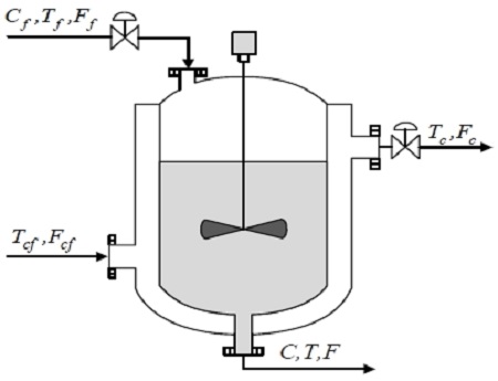
A reaction occurring in CSTR is either exothermic or endothermic. Thus, to maintain a constant temperature of the reactor, it needs to be cooled or heated by an external medium. Figure 1 shows the schematic diagram of a CSTR process, where an exothermic reaction was considered. In the figure Cf, Tf, Ff and C, T, F represent the concentration [mol/m3], temperature [K], and flux [m3/sec] at the inlet and outlet of the fluid, respectively; and Tcf, Fcf and Tc, Fc represent the temperature and flux at the inlet and outlet of the coolant, respectively.
To simplify the problem, it is assumed that the irreversible reaction is an exothermic reaction, and the reaction is the first order system with respect to the reactant. It is also assumed that the fluid in the reactor is well stirred, the input and output fluxes are identical, and the parameters are constant regardless of the temperature. When the material and energy conservation laws are applied to the CSTR process, the following dimensionless dynamic equations can be obtained [1].
| (1a) |
| (1b) |
| (1c) |
where x1 and x2 are the state variables that represent the concentration C and the temperature T, respectively; y and u are the fluid outlet temperature and the coolant temperature, which are output and input of the CSTR, respectively; and d1 and d2 are the disturbances. Also, Da is the Damökhler number, H is the heat of reaction, β is the heat transfer coefficient, V is the volume of the CSTR [m3], γ = E/RTf, E is the activation energy [cal/mol], and R is the gas constant [cal/mol-K].
In this regard, the x1, x2, u, and t in Equation (1) are made to be dimensionless as shown in Equation (2).
| (2a) |
| (2b) |
Considering the physical limit of the control valve that operates for temperature control in the CSTR process, it is assumed that a saturator expressed as the following nonlinear equations exists between the controller and the CSTR process.
| (3) |
where umin and umax are the minimum and maximum values of the saturator, respectively; and usat is the output of the saturator or control input.
Thus, the control system that combined the saturator and the CSTR process can be expressed as a block diagram as shown in Figure 2.
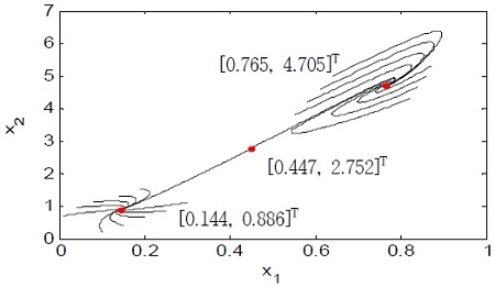
When the open loop system in Eq. (1) has the values of Da= 0.072, γ = 20, H =8, and β=0.3 in a steady state, three equilibrium points (xeA= [0.144, 0.886]T, xeB= [0.447, 2.752]T, and xeC = [0.765, 4.705]T) exist, where xeA and xeC are stable equilibrium points and xeB is an unstable equilibrium point. Figure 3 shows the three equilibrium points on a phase diagram.
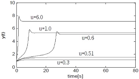
Figure 4 shows the open loop responses of the CSTR for the various step inputs. As shown in the figure, the response and the gain vary significantly depending on the step input. In particular, when the step input is smaller than 1, a very small difference in the input has a large effect on the esponse. Due to this strong nonlinearity, it is not easy to control the CSTR using an existing linear PID controller.
3. Fuzzy PD plus I Controller
3.1 Basic structure of a Fuzzy-PD controller
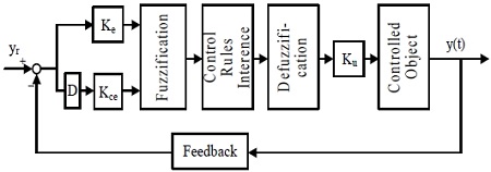
A fuzzy PD controller generally consists of fuzzification, fuzzy inference by fuzzy rules, and defuzzification, as shown in Figure 5.
For the inputs of the fuzzy PD controller, there are two kinds of signals (the error and the variation in the error) as shown in Equation (4); and the output is defined as u(t).
| (4) |
where yr(t) is the set point, E and ΔE are the linguistic variables for the error and the variation in the error, respectively, Ke and Kce are the scaling factors for the input signals, and F(·) represents the fuzzy inference.
The fuzzy sets of the linguistic variables for all the input/output of the fuzzy PD controller used in this study were defined by normalization as [-1 1] as follows.
| (5) |
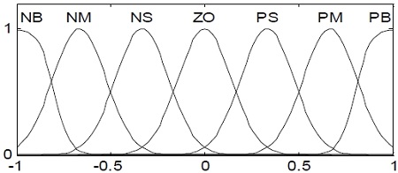
The linguistic labels used to describe the fuzzy sets are ‘negative big’ (NB), ‘negative medium’ (NM), ‘negative small’ (NS), ‘zero’ (Z), ‘positive small’ (PS), ‘positive medium’ (PM), ‘positive big’ (PB). For the membership function, a Gaussian-type fuzzy set was used as shown in Figure 6.
For convenience, the fuzzy rules are summarized in Table 1; and they are interpreted as follows.
| (6) |
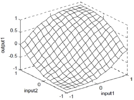
For the fuzzy rules, widely used rules based on the experience and knowledge of humans were used, and all the rules consisted of fuzzy relationships. For the fuzzy inference, the Max-Min method was used based on the Mamdani type; and for the defuzzification, the center of gravity method was applied. Figure 7 shows the control surface of the fuzzy PD controller.
3.2 Structure of a Fuzzy PD plus I controller
A series of studies using fuzzy technique have recently been conducted, but they perform control by obtaining a linear model at one operating point of CSTR [10][11]. In the present study, a fuzzy PD plus I controller that combined a fuzzy PD controller in parallel with a linear integral controller was used to control the temperature of CSTR, and the performances for the set-point tracking and for the parameter change in the CSTR were improved.
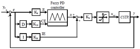
As shown in Figure 8, the fuzzy PD plus I controller can improve the steady-state performance of CSTR temperature through the linear integral controller that is added after the fuzzy inference of the fuzzy PD controller. In Figure 8, Ke and Kce are the scaling factors for the fuzzy input variables, Ku is the scaling factor for the fuzzy output variable, and Kie is the gain of the linear integral controller. Appropriate scaling factors for input and output signals enable flexible and adaptive response to the dynamic characteristics of the control target. In this study, they were determined by trial and error.
4. Computer Simulation Results
4.1 Control technique of the comparison target
Chen and Peng [4] recently suggested an adaptive controller for a system with saturator umin ≤ u(t) ≤ umax, and the control input can be expressed as Equation (7).
| (7) |
where is a hyperbolic tangent function, and is expressed as follows.
| (8) |
where e(t) is the error between the set point and the output, m is the slope, and θ(t) is the bias. has a value between -1 and 1, and thus, u(t) is maintained within the limit value of the saturator.
As shown in Equation (8), has two adjustable parameters. In particular, the size and sign of the slope m sensitively respond to the characteristics of the controller. Thus, Chen and Peng suggested an algorithm that fixes m and adaptively adjusts only the bias θ(t) depending on the problem.
The tuning algorithm of θ(t) can be expressed as follows.
| (9) |
where η is the learning rate, and it is a positive number. is the value of ±1 that is determined by the response direction of the system, and it is obtained from a step response experiment or the physical characteristics of the control target. In this way, the algorithm continuously adjusts the parameters of the controller based on the error between a set point and an actual output. In addition, in Korkmaz et al. [3] that was also used for comparison, the structure of an existing linear PID controller was maintained, and three gains were nonlinearly changed. The nonlinear PID (NPID) controller of Korkmaz is expressed as Equation (10).
| (10) |
where Kp(e), Ki(e), and Kd(e) are nonlinear functions based on the error e and the Gaussian error function, and they play roles similar to the proportional, integral, and derivative gains of a linear PID controller.
| (11) |
where,
The controller gain parameters a1, a2, b, and c in Equation (11) are positive constants, and are appropriately adjusted by a user. Based on this, NPID controller of Korkmaz operates so that the proportional and derivative gains can be increased when the absolute value of the error is large and so that the integral gain can reduce the steady-state deviation when the absolute value of the error is small.
4.2 Data and controller parameters for the simulation
For the data of the CSTR used in the simulation, Da=0.072, γ= 20, H= 8, β= 0.3, the upper and lower limit values of the saturator were ±5, and the sampling interval was 0.01.
Chen and Peng used η= 0.2 and m= 5 for the temperature control of CSTR with a saturator, and was 1 because a CSTR process has positive gain. For the parameters a1, a2, b, and c of the NPID controller in Korkmaz et al. [3], 35.87, 21.70, 43.33, and 2.73 were used, respectively.
In addition, the scaling factors of the fuzzy PD plus I controller shown in Figure 8 were selected to be Ke=1.2, Kce=0.1, Ku=55, and Kie=1.8 through trial and error.
4.3 Performance comparison
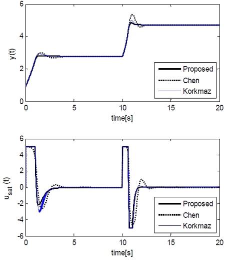
First, a set-point tracking experiment was conducted considering a control environment that changes the temperature at the outlet of the CSTR coolant. In the experiment, when the process was in a stable equilibrium state (xeA = [0.144, 0.886]T), the set point was step-wisely increased to yr = 2.75, which changed the output y to an unstable equilibrium state xeB. Then, at t= 10, it was again step-wisely increased to yr=4.705, which led to a stable equilibrium state xeC. Figure 9 shows the output y and the saturator output usat.
As shown in the figure, both the adaptive controller of Chen and Peng and the NPID controller of korkmaz reached the set point without a steady-state error, but the proposed method approached quickly with a smaller overshoot than those of the other two methods. In particular, for all the controllers, the overshoot of the response was larger when it was changed from xeB to xeC compared to when it was changed from xeA to xeB; and this is considered because of the intrinsic nonlinearity of the CSTR.
Table 2 summarizes the overshoot (Mp), rising time (tr=t90-t10), and 2% setting time (ts) in order to compare the performances of the three methods. In this regard, t10 and t90 refer to the times required for the output to reach 10% and 90% of the set point, respectively. As summarized in the table, the proposed method showed superior performance compared to the other two methods.

Comparison of set-point tracking performances when set point yr is step-wisely increased from 0.886 to 4.705.
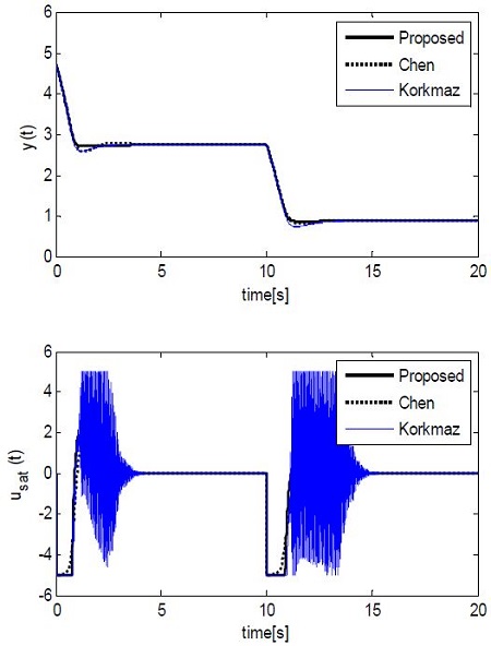
As for the intrinsic nonlinearity of the CSTR, the response characteristics could vary when the set point yr is increased or decreased. Figure 10 shows the response where the set point yr was changed to 2.75 when the process was in an equilibrium state (xeC = [0.765, 4.705]T), and the yr was again stepwisely decreased to 0.886 at t = 10 when the process was at xeB. Table 3 summarizes the performances of the three methods, similar to Table 2.
In particular, for the NPID controller of korkmaz, the control input showed significant hunting.
The performance of the controller regarding the change in the parameter of the CSTR was examined. As the CSTR was expressed as dimensionless dynamic equations, it was not easy to consider the change in the parameter. Thus, in this study, it was assumed that the heat transfer coefficient β decreased due to the long-term use of the CSTR.
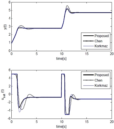
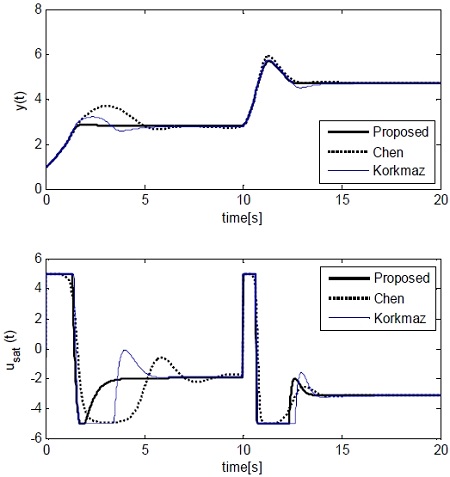
An experiment was first performed assuming a 20% decrease in the nominal value of the heat transfer coefficient β (to 0.24 from 0.3 ) (Figure 11), and an experiment was then performed assuming a 40% decrease to 0.18 (Figure 12). As shown in the figures, the proposed method was more robust to the parameter changes than the other two methods.
In particular, when the β was decreased by 40%, the adaptive controller of Chen and the NPID of Korkmaz showed large overshoot.
5. Conclusion
This study dealt with the temperature control of a CSTR process based on a fuzzy PD plus I controller. A fuzzy PD plus I controller was designed by considering a saturator that is commonly used for a control valve on the sites, combining a fuzzy PD controller in parallel with a linear integral controller, and selecting the scaling factors through trial and error. To examine the validity of the proposed method, the set-point tracking performance and the parameter change performance were compared with those of an adaptive controller and an NPID controller, and the results indicated that the control performance was improved. In the future, studies on the optimal tuning of the scaling factors using optimization tools are needed.
References
- W. H. Ray, Advanced Process Control, McGraw-Hill Book Co, N.Y, (1981).
-
J. P. Corriou, Process Control: Theory and Applications, Springer-Verlag, London, (2004).
[https://doi.org/10.1007/978-1-4471-3848-8]

-
M. Korkmaz, O. Aydogdu, and H. Dogan, “Design and performance comparison of variable parameter nonlinear PID controller and genetic algorithm based PID controller”, Proceedings of the IEEE International Symposium on Innovations in Intelligent Systems and Applications, p1-5, (2012).
[https://doi.org/10.1109/inista.2012.6246935]

-
C. T. Chen, and S. T. Peng, “Learning control of process systems with hard input constraints”, Journal of Process Control, 9(2), p151-160, (1999).
[https://doi.org/10.1016/S0959-1524(98)00038-9]

-
L. S. Saoud, F. Rahmoune, V. Tourtchine, and K. Baddari, “An inexpensive embedded electronic continuous stirred tank reactor (CSTR) based on neural networks”, Proceedings of the International Conference on Multimedia Technology, p6233-6237, (2011).
[https://doi.org/10.1109/icmt.2011.6002445]

-
U. S. Banu, and G. Uma, “Fuzzy gain scheduled pole placement based on state feedback control of CSTR”, Proceedings of the International Conference on Information and Communication Technology in Electrical Sciences, p63-68, (2007).
[https://doi.org/10.1049/ic:20070588]

- M. A. Nekoui, M. A. Khameneh, and M. H. Kazemi, “Optimal design of PID controller for a CSTR system using particle swarm optimization (PSO)”, Proceedings of the 14th International Power Electronics and Motion Control Conference, pT7-63-T7-66, (2010).
-
S. Tong, T. Wang, and J. T. Tang, “Fuzzy adaptive output tracking control of nonlinear systems”, Fuzzy Sets and Systems, 111(2), p169-182, (2000).
[https://doi.org/10.1016/S0165-0114(98)00058-X]

-
I. Rojas, H. Pomares, J. Gonzalez, L. J. Herrera, A. Guillen, F. Rojas, and O. Valenzuela, “Adaptive fuzzy controller: Application to the control of the temperature of a dynamic room in real time”, Fuzzy Sets and Systems, 157(16), p2241-2258, (2006).
[https://doi.org/10.1016/j.fss.2006.03.006]

- S. Boobalan, K. Prabhu, and V. Murali Bhaskaran, “Fuzzy based temperature controller for continuous stirred tank reactor”, International Journal of Advanced Research in Electrical, Electronics and Instrumentation Engineering, 2(12), p5835-5842, (2013).
- D. F. Ahmed, and M. N. Esmaeel, “Fuzzy logic control of continuous stirred tank reactor”, Tikrit Journal of Engineering Sciences, 20(2), p70-80, (2013).

