Characteristics Evaluation on Welding Metal Zones Welded with Inconel 625 Filler Metal to Cast Steel for Piston Crown Material
Copyright © The Korean Society of Marine Engineering
This is an Open Access article distributed under the terms of the Creative Commons Attribution Non-Commercial License (http://creativecommons.org/licenses/by-nc/3.0), which permits unrestricted non-commercial use, distribution, and reproduction in any medium, provided the original work is properly cited.
Abstract
Since the oil price has been significantly jumped for several years, a heavy oil of low quality has been mainly used in the diesel engine of the merchant ship. Thus, a combustion chamber of the engine has been often exposed to severely corrosive environment more and more because temperature of the exhaust gas of the combustion chamber has been getting higher and higher with increasing of using the heavy oil of low quality. As a result, wear and corrosion of the engine parts such as exhaust valve, piston crown and cylinder head surrounded with combustion chamber are more serious compared to the other parts of the engine. Therefore, an optimum repair welding for these engine parts is very important to prolong their lifetime in a economical point of view. In this study, Inconel 625 filler metal were welded with GTAW method in the cast steel which would be generally used with piston crown material. And the corrosion properties of weld metal, heat affected and base metal zones were investigated using electrochemical methods such as measurement of corrosion potential, anodic polarization curves, cyclic voltammogram and impedance etc. in 35% H2SO4 solution. The weld metal and base metal zones exhibited the highest and lowest values of hardness respectively. Furthermore, the corrosion current density of the weld metal zone revealed the lowest value, having the highest value of hardness. The corrosive products with red color and local corrosion like as a pitting corrosion were considerably observed at the base metal zone, while these morphologies were not wholly observed in the weld metal zone. In particular, the polarization characteristics such as impedance, polarization curve and cyclic voltammogran associated with corrosion resistance property were well in good agreement with each other. Consequently, it is suggested that the mechanical and corrosion characteristics of the piston crown can be predominantly improved by repair welding method using the Inconel 625 electrode.
Keywords:
Repair welding, Inconel 625 filler metal, GTAW, Weld metal zone, Electrochemical method, Corrosion current density, Hardness1. Introduction
In recent years, low quality heavy oil with high viscosity and high levels of impurities has mostly been used in the diesel engines of the merchant marine ships because the oil price has significantly jumped over the last several years. As a result, the vanadium and sulfide present in the heavy oil has also caused either a high and low temperature corrosion [1] or wear of the engine parts, such as exhaust valve, piston crown and cylinder head surrounded with combustion chamber. Therefore, the damaged engine parts caused by corrosion and wear mentioned above are recovered by repair welding, and these engine parts surrounded by combustion chamber can be used again through repair welding, which is an economic way to extend their lifetimes. Furthermore, when a ship is newly constructed, the upper part of the piston crown would also be deposited with the weld metal zone via a repair welding method with some types of filler metals to inhibit its wear and corrosion.
Several welding methods can be used, i.e., repair welding and general welding, to manufacture steel structures, and numerous papers associated with the mechanical properties [2]-[4] and corrosion [5]-[10] of welding zones have been reported. On the other hand, there are few reports of an evaluation of the mechanical and corrosion properties on the welding zones of the upper part of the piston crown was investigated using electrochemical method. Therefore, in this study, repair welding with an Inconel 625 filler metal was performed on the cast steel, which would generally be used with piston crown material. In addition the corrosion properties of weld metal, heat affected and base metal zones were investigated using electrochemical methods in a 35% H2SO4 solution. Consequently, the results of this study may provide good reference data on the mechanical and corrosion characteristics of each welding zone when the upper part of the piston crown is welded with Inconel 625 filler metals.
2. Experimental procedure
The specimen of the base metal used for repair welding was a heat resistance steel with a Cr-Mo low alloy, which is generally used with a piston crown material. The base metal specimen was prepared with a thickness of 30mm, a width of 250mm and a length of 400mm. A 20 mm hole with a depth of 3.5mm was made artificially in its center area, and the hole was deposited with repair welding using Gas Tungsten Arc Welding (GTAW) with Inconel 625 filler metal.
The welding method was performed from the DC 1st layer to the 5th layer, and the test specimen was manufactured again with a thickness of 10mm, a width of 20mm and a length of 40mm using the lathe process. Table 1 and 2 list the chemical composition of the base metal and Inconel 625 filler metal, respectively.
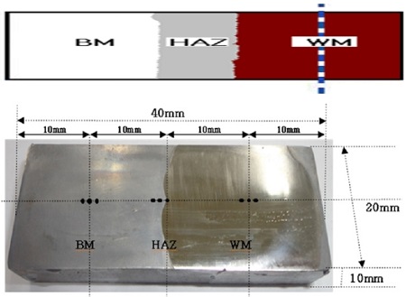
Figure 1 shows a photograph of the test specimen etched with an aqua regia solution and a schematic diagram of the welding area. The surface of the test specimen was polished with sand paper from No.200 to No.2000, degreased with acetone, and insulated with epoxy coating except for an area of 1cm2 (0.25cm2 for heat affected zone) for the electrochemical test. Areas of 1cm2 (WM, BM) and 0.25cm2 (HAZ) were obtained in the center point of three points in each welding zone, respectively. The polarization curves were measured using the CMS105 program (Gamry Co.UK) in a 35% H2SO4 solution with a flowing condition of 3cm/s that was calculated by particle image velocimetry (Scanning speed : 1mV/s, counter electrode : Pt wire, reference electrode: SCE), The surface morphology of the corroded surface was observed by scanning electron microscopy (SEM, Model: SV35, Sometech, Com, Ltd). The Vickers hardness was measured in three points (the distance between each point is 2mm) of each welding area, such as the base metal, heat affected and weld metal zones, as shown in Figure 1, and their average values were obtained.
3. Results and discussion
Figure 2 shows the variation of the Vickers hardness of each welding zone in the case of weld with Inconel 625 filler metal. The weld metal and heat affected zones exhibited higher hardness values than the base metal zone, and the weld metal zone showed the highest hardness. Moreover, the hardness of the heat affected zone was similar to that of the weld metal zone. The hardness of the weld metal zone tended to increase due to either movement of the metal component of a filler metal from the weld metal zone to the base metal zone or movement of the base metal component from the base metal zone to the weld metal zone [11]-[13]. As shown in Table 1 and 2, the chemical components, such as Cr, Mo and Ni, were included in Inconel 625 filler metal compared to the base metal. Therefore, the metal components of the filler metal are concentrated on the weld metal zone regardless of the movement of the metal component, which result in an increase in the hardness of the weld metal zone, or a quenching effect of the weld metal zone may lead to a slight increase in hardness.
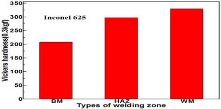
Comparison of the Vickers hardness of each welding metal zone in the case of the welded with the Inconel 625 filler metal
Figure 3 shows the morphologies of microstructures of the each welding zone. The morphologies of the base metal and weld metal zones were photographed in the center point of the three points in each welding zone; however, the morphology of heat affected zone was photographed at the right point of three points (bond zone between heat affected and weld metal zones), as shown in Figure 1. The microstructure of the pearlite with black color was observed in the base metal zone. In addition, the bond line was observed at the bound area between the weld metal zone (left side) and heat affected zone (right side). Moreover, the microstructure of pearlite with a black color increased considerably at the heat affected zone than that of the weld metal zone. Furthermore, a large amount of ferrite microstructure with a white color was observed in the weld metal zone compared to the other welding zones. Therefore, there appears to be a relationship between the ferrite microstructure and the hardness, i.e., the hardness increased with increasing ferrite microstructure, as shown in Figure 2 and 3. As a result, the variation of these microstructures according to the welding zones may result in a large amount of elements, such as Cr, Ni and Mo, which are included in the filler metal.
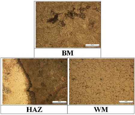
Comparison of microstructures of each welding zone in the case of the welded with Inconel 625 filler metal(x500)
Figure 4 shows the variation of corrosion potentials in each welding zone. The weld metal and base metal zones exhibited the noblest and lowest corrosion potentials, respectively. The heat affected zone revealed a medium value. Therefore, the weld metal zone has the best corrosion resistance qualitatively compared to the heat and base metal zones.
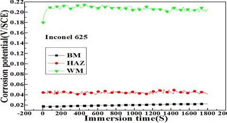
Variation of corrosion potentials in each welding zone in the case of welded with the Inconel 625 filler metal
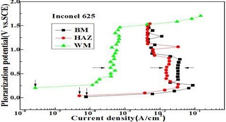
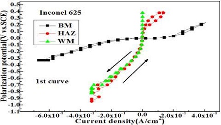
Figure 5 shows the variation of anodic polarization curves of each welding zone. As shown in Figure 5, the passivity current density indicating with the horizontal arrow exhibited the largest and smallest values in the weld metal and base metal zones respectively. On the other hand, to confirm their corrosion properties, it will be necessary to obtain the corrosion current densities quantitatively from the anodic polarization curve. Generally, the theoretical Bulter-Volumer equation for the corrosion current density can be expressed as Equation (1)[14],
| (1) |
and Equation (1) can be transformed with Equation (2)
| (2) |
Equation (2) is also known as a Tafel experimental equation estimating the corrosion current density when an active corrosive specimen is submerged in seawater, i.e., its corrosion potential should be in the activation condition. On the other hand, if its corrosion potential is not located in the activation condition, e.g., the test specimen is in the passivity condition in the corrosive solution, an accurate value of the corrosion current density may not be obtained by the polarization curves using the Tafel extrapolation method. Therefore, the vertical arrows shown in Figure 5 would indicate the current densities corresponding to the corrosion potentials. Thus, this current density can be assumed approximately to be the corrosion current density [15].
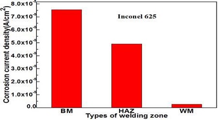
Figure 6 compares the corrosion current densities of each welding zone obtained from Figure 5. The weld metal zone indicates the smallest corrosion current density, while the base metal zone exhibited the largest value. As a result, the higher hardness, the larger ferrite microstructure, the nobler corrosion potential, and the smaller passivity current density. As shown in Figure 2, 3, 4, and 5, the corrosion resistance has apparently increased. Therefore, there is a somewhat good relationship between the corrosion resistance and hardness, which results in a large amount of metal components, such as Cr, Mo and Ni, included in the Inconel 625 filler metal mentioned above.
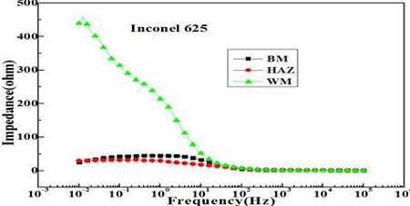
Figure 7 shows variation of the impedances of each welding zone measured in a 35 % H2SO4 solution. The impedances at 0.01Hz represent the highest and lowest values in the weld metal and base metal zone, respectively. In particular, the impedance of the weld metal zone is the highest compared to the heat and base metal zones.
Figure 8 shows variation of cyclic voltammetry curves of each welding zone. The cyclic voltammetry curve of the base metal zone significantly declined both to the right and left direction, while the curves of the weld metal and heat affected zones exhibit nearly vertical patterns compared to the base metal zone. As a result, the polarization resistance of the weld and heat affected zones is larger than that of the base metal zone. Therefore, the results of Figure 7 and 8 well agree with the results in Figure 6, e.g., the corrosion current density of the weld metal zone increases with increasing impedance at 0.01Hz, and with increasing polarization resistance of cyclic voltammetry curve.
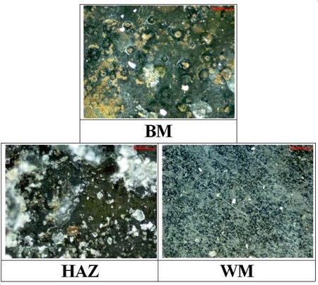
Figure 9 shows the morphologies of the corroded surfaces of each welding zone after measurements of the anodic polarization curves. The corrosive products with red and white colors were observed at the surface of the base metal and heat affected zones, respectively. In addition, local corrosion, such as a pitting corrosion, was also observed at the base metal zone. On the other hand, these morphologies were not wholly observed at the surface of the weld metal zone. Therefore, the corrosion resistance of the weld metal zone is considered to be better than those of the base metal and heat affected zones.
4. Conclusions
When repair welding using the Inconel 625 filler metal was carried out on cast steel, which is generally used with piston crown material, the mechanical and corrosion properties for each welding zone were investigated using an electrochemical method. The weld metal and base metal zones exhibited the lowest and highest corrosion current densities, and the highest and lowest hardness, respectively. Furthermore, the corrosive products with red and white colors were observed at the base metal and heat affected zones respectively; however, these corrosive products were not wholly observed at the weld metal zone. Moreover, the microstructure of the pearlite with a black color was observed at the base metal and the heat affected zone, while the ferrite microstructure with a white color was observed at the weld metal zone. In particular, the polarization characteristics, such as impedance, polarization curve and cyclic voltammogram curve associated with corrosion resistance property, were in good agreement with each other. Consequently, it is assumed that the mechanical and corrosion characteristics of the piston crown can be improved predominantly by a repair welding method using an Inconel 625 electrode.
Acronyms
| a : | 2.3RT/αnF |
| b : | -2.3RT/αnF, η <0 |
| ŋ : | cathodic overvoltage (E - Ecor )(V) |
| α, β : | transfer coefficient |
| F : | Faraday constant (C/mol) |
| T : | absolute temperature (K) |
| R : | gas constant (J/K•mol) |
| n : | ionic number |
References
- D. H. Jeon, Control of the Corrosion and Anti-corrosion, Busan, Iljoongsha, p426-428, (1985), (in Korean).
- J. G. Kim, M. S. Kang, and Y. S. Kim, “A study on characteristics of repair welding for cast iron part of diesel engine for ship”, Journal of Ocean Engineering and Technology, 20(2), p41-45, (2006), (in Korean).
- J. D. Kim, B. L. Kil, and C. J. Lee, “The weldability of haminated stator core for motor by pulsed Nd:YAG laser [I]”, Journal of the Korean Society of Marine Engineering, 30(5), p629-635, (2006).
- J. D. Kim, S. J. Yoo, and J. S. Kim, “Optimization of pulsed Nd:YAG laser welding conditions for sealing of lithium-ion battery”, Journal of the Korean Society of Marine Engineering, 30(5), p623-628, (2006).
-
P. D. Bilmes, C. L. Liorente, Saire Huaman, L. M. Gassa, and C. A. Gervasi, “Microstructure and pitting corrosion of 13CrNiMo weld metal”, Corrosion Science, 48, p3261-3270, (2006).
[https://doi.org/10.1016/j.corsci.2005.10.009]

- Y. H. Lee, Y. H. Kim, and H. Kim, “Crevice corrosion resistance of stainless steel in natural sea water with different post welding treatment”, Corrosion Science and Technology, 2(5), p219-224, (2003).
- I. H. Lo, M. C. Lee, K. Y. Lim, W. Ho, G. C. Y. Yang, and W. T. Tsai, “Effect of heat treatment on the pitting corrosion behavior of 347SS weld overlay”, Corrosion Science and Technology, 31(5), p361-367, (2002).
- K. M. Moon, M. H. Lee, K. J. Kim, J. G. Kim, and S. J. Kim, “A study on the post-weld heat treatment effect to mechanical properties and hydrogen embrittlement for heating affected zone of a RE36 steel”, Corrosion Science and Technology, 2(6), p283-288, (2003).
-
V. S. Raja, S. K. Vershney, R. Raman, and S. D. Kulkarni, “Influence of nitrogen on the pitting corrosion behavior of 904L weld clad”, Corrosion Science, 40(10), p1609-1625, (1998).
[https://doi.org/10.1016/S0010-938X(97)00174-1]

-
L. W. Tsay, W. L. Lin, S. W. Chenct, and G. S. Leu, “Hydrogen sulphide stress corrosion cracking of 2.25 Cr- Mo steel weldments”, Corrosion Science, 39(7), p1165-1176, (1997).
[https://doi.org/10.1016/S0010-938X(97)00015-2]

- S. H. Ahn, J. H. Jeong, and K. W. Nam, “Evaluation of characteristic for SS400 and STS304 steel by weld thermal cycle simulation”, Journal of Ocean Engineering and Technology, 19(4), p64-71, (2005), (in Korean).
- D. H. Jeon, Control of the Corrosion and Anti-corrosion, Busan, Iljoongsha, p294-298, (1985), (in Korean).
- M. K. Shin, New Edition Workshop Practice, Ah Sung Publishing Co, p242-245, (1984), (in Korean).
- K. M. Moon, Practical Electrochemistry, Hyosung Publishing Co, p177, (1999), (in Korean).
- K. M. Moon, J. P. Won, D. H. Park, S. Y. Lee, J. A. Jeong, M. H. Lee, and T. S. Baek, “Evaluation on the polarization characteristics of embedded steel bar of mortar specimen (W/C:0.4) with Passing Aged Years”, Corrosion Science and Technology, 13(20), p20, (2014), (in Korean).


