The Effect of Annealing Heat Treatment by Anodic Polarization Impedance Experiments for Cu-10%Ni Alloy
Copyright © The Korean Society of Marine Engineering
This is an Open Access article distributed under the terms of the Creative Commons Attribution Non-Commercial License (http://creativecommons.org/licenses/by-nc/3.0), which permits unrestricted non-commercial use, distribution, and reproduction in any medium, provided the original work is properly cited.
Abstract
Copper has been used extensively as an electric wire or as a base material in various types of machineries owing to its good electrical and thermal conductivity and good fabricating property, as well as its good corrosion resistance compared to iron. Furthermore, the copper-nickel alloy has significant corrosion resistance in severely corrosive environments. Although, cupro-nickel alloy shows better corrosion resistance than the brass and bronze series, this alloy also corroded in severely corrosive environments, including aggressive chloride ions, dissolved oxygen, and condition of fast flowing seawater. In this study, and annealing treatment at various annealing temperatures was carried out on the cupro-nickel (Cu-10%Ni) alloy, and the effects of annealing were investigated using electrochemical methods, such as measuring the polarization and impedance behaviors under flowing seawater conditions. The corrosion resistance increased by annealing compared to non heat treatment in the absence of flowing seawater. In particular, the sample annealed at 200 ℃ exhibited the best corrosion resistance. The impedance in the presence of flowing seawater showed higher values than in the absence of flowing seawater. Furthermore, the highest impedances was observed in the sample annealed at 800 ℃, irrespective of the present of flowing seawater. Consequently, the corrosion resistance of cupro-nickel (Cu-10%Ni) alloy in a severely corrosive environment can be improved somewhat by annealing.
Keywords:
Cupro-nickel alloy, Corrosion resistance, Polarization characteristics, Annealing heat treatment, Impedance1. Introduction
Copper is used widely as an electric wire or as a metal material in various types of machinery because of its good electrical and thermal conductivity and good fabricating property, as well as its good corrosion resistance compared to iron. On the other hand, if impurities are involved in pure copper, its corrosion resistance decreases significantly due to the corrosion of impurities, which act selectively as an anode. Therefore, to improve its corrosion resistance and mechanical property in severe corrosive environments, various types of copper alloys containing metal components, such as Zn and Sn, have been manufactured continuously [1]. Nevertheless, copper alloys, such as the brass series (Cu-Zn) and bronze series (Cu- Sn), are often exposed to several types of corrosion, such as dezincification corrosion, stress corrosion cracking and pitting corrosion under a more severe corrosive environment. In addition, a cation of Cu dissolved in an electrolyte generally has an anti-fouling effect. Therefore, copper and its alloy is sometimes used as an anode for the formation of cations or as an inhibitor for cathodic protection [2]-[7]. Although the Cu cation has an anti-fouling effect, in the case of exposing it to alloy steel based on Fe, a galvanic corrosion can sometimes occur as a result of Cu due to the potential difference between Cu and Fe. Therefore, galvanic corrosion can generally be controlled using the Al cation by the dissolution of Al. On the other hand, copper alloys with extremely good corrosion resistance as well as good electrical and thermal conductivity in various fields have been used widely in severely corrosive environments. One of the copper alloys mentioned above is the cupro- nickel (Cu-Ni) alloy [8]. This alloy has a high corrosion resistance with increasing amount of Ni, and has been often widely used in heat exchangers and condensers etc. [9][10]. Although the cupro-nickel alloy has better corrosion resistance than those of the brass and bronze series, it was reported that its alloy should corrode in severe corrosive environments, including aggressive chloride ions, dissolved oxygen and the condition of fast flowing seawater. On the other hand, it was reported that the resistance to stress corrosion cracking in the case of brass would be increased considerably, leading to slightly low hardness by annealing heat treatment. In this study, an annealing heat treatment at different heating temperatures was carried out on the cupro-nickel alloy, and the effects of the annealing heat treatment on its polarization characteristics were investigated using electrochemical methods with non flowing and flowing seawater. The results of this study may provide good reference data to improve the corrosion resistance of cupro-nickel alloys when exposed to severe corrosive environments, including aggressive chloride ions and dissolved oxygen in seawater.
2. Experimental procedure
Table 1 lists the chemical composition of the test specimen. The specimen was provided by Dong Wha Co.Ltd., and was imported from Japan. As shown in Table 1, this Cu-10% Ni alloy specimen consisted of not only the main components of Cu, Ni but also small amounts of Fe, Mn and the other chemical compositions. The annealing heat treatment at temperatures of 200 ℃, 700 ℃, 800 ℃, 900 ℃, and 1000 ℃ for 1hr was performed on the Cu-10% Ni alloy specimen with cold rolling. An electric bath (Shin Saeng Co.Ltd, Model:8EF 101, 200V, 3KW) was used for the annealing treatment. For the electrochemical measurement, the specimens were cut with dimensions of 3.0ⅹ1.0ⅹ0.2 cm, and these specimens were polished with emery papers ranging from No. 200 to No. 2000 consecutively. These specimens were then washed with distilled water, and degreased with acetone. The exposed surface area for the electrochemical test was 1cm2, whereas the remaining area was insulated with epoxy resin.
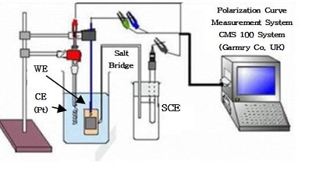
The potentiodynamic anodic polarization curves, and impedance (10-2Hz~105Hz) were measured using the CMS 100 program (Gamry Co, UK) in the presence or absence of flowing of 3cm/s in seawater, which was calculated by particle image velocimetry (scanning speed of the polarization curves: 1mV/s, counter electrode: Pt wire, reference electrode: SCE). Figure 1 shows the experimental apparatus for measuring the polarization curves and impedance.
3. Results and discussion
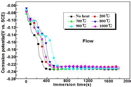
Figure 2 shows the variation of the corrosion potentials with various annealing temperatures in the presence of flowing seawater. As shown in Figure 2, all corrosion potentials, irrespective of annealing heat treatment and of non-heat treatment, have shifted rapidly to the negative direction, and reached a plateau after approximately 400 seconds. Moreover, the corrosion potentials of the heat treatment specimens exhibit relatively nobler values than the non-heat treatment specimens. Therefore, the corrosion resistance in a seawater solution is increased qualitatively by heat treatment.
Figure 3 presents the anodic polarization curves with and without flowing seawater in the case of non-heat treatment. As shown in Figure 3, the vertical arrow located at the right side indicates the peak current density. The peak current density of the flowing condition exhibit an apparently larger value rather than that of the non-flowing condition; however, its passivity current density (horizontal arrow) has a smaller value than that of the non-flowing condition.
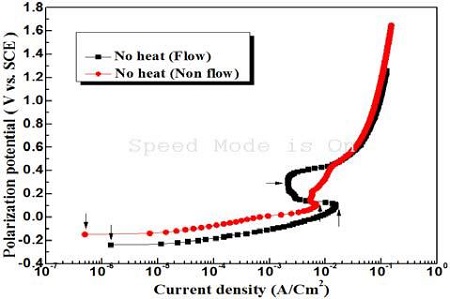
Anodic polarization curves with and without flowing condition of seawater in the case of non heat treatment
This is probably because aggressive chloride ions make it easier to diffuse and penetrate the oxide film on the surface due to flowing seawater, which results in an increase in peak current density. On the other hand, as the cupro-nickel alloy has good corrosion resistance in seawater, dissolved oxygen can also diffuse easily to the surface in the case of the flowing condition. Therefore, as soon as the active peak condition has passed, the oxide film formed by a strong reduction power with a large amount of oxygen is believed to show a smaller passivity current density than that of the non-flowing condition. The corrosion current density on the polarization curve can be obtained using a Tafel extrapolation method. In this case, the corrosion potential should be in the activation condition. If, however, the corrosion potential is not in the activation condition, an accurate value of the corrosion current density might not be obtained on the polarization curves using the Tafel extrapolation method. The Cu-10% Ni alloy specimen used in this study would generally have a high corrosion resistance in seawater. Therefore, the corrosion potential of this specimen in seawater may not be wholly in the activation condition, but almost in the passivity condition. Therefore, it is believed that the Tafel extrapolation method may not be an accurate method for obtaining the corrosion current density. As shown in Figure 3, the vertical arrows located at the left most side indicate the current densities corresponding to the corrosion potentials. Therefore, this current density can be assumed to be approximately the corrosion current density [11]. Hence, the corrosion current density of the non-flowing condition exhibits a smaller value than that of the flowing condition.
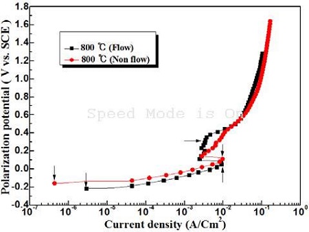
Figure 4 shows the anodic polarization curves in the presence and absence of flowing seawater of the sample annealed at 800 ℃. At an annealing temperature of 800 ℃, the peak current density exhibits similar values regardless of the non-flowing and flowing condition, which suggests that the annealing heat treatment enhances the corrosion resistance by forming an oxide film rapidly even in flowing seawater. On the other hand, the corrosion current density of the non-flowing condition also indicates a smaller value than that of the flowing condition.
Figure 5 compares the anodic polarization curves measured under various annealing temperatures in the absence of flowing seawater. Most of the curves show similar patterns, irrespective of the annealing temperature. Thus, the peak current densities and passivity current densities cannot be observed. As shown in Figure 5, however, the corrosion current densities indicated with the vertical arrows represent different values according to the various annealing temperatures.
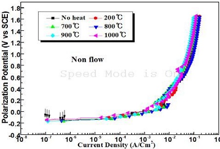
Comparison of anodic polarization curves with various annealing temperatures in the absence of flowing condition of seawater
Figure 6 shows the variations of the anodic polarization curves of the samples annealed at various annealing temperatures in the presence of flowing seawater. Figure 6 shows that in the presence of flowing seawater, their current densities, i.e., the passivity and peak current densities can be observed on the anodic polarization curves compared to the non-flowing condition in Figure 5. In flowing seawater, the aggressive chloride ions can arrive easily at the surface of the specimen, making it more difficult to form an oxide film on the surface due to accelerated corrosion by chloride ions, which results in increasing peak current density. On the other hand, dissolved oxygen can also diffuse easily to the surface. Furthermore, the cupro-nickel alloy has strong reduction power to form an oxide film using oxygen, making it easier to form an oxide film, hence a passivity region is assumed to have appeared.
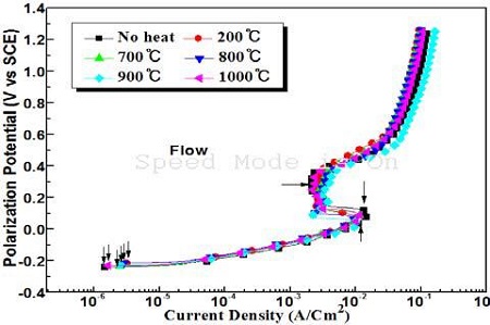
Comparison of anodic polarization curves at various temperatures in the presence of flowing seawater
Figure 7 shows the variation of the corrosion current densities at different annealing temperatures obtained from Figure 5 and 6. The corrosion current densities in the presence of flowing seawater increased significantly compared to that in non-flowing seawater. Furthermore, the corrosion current densities of flowing condition increased with annealing compared to non-heat treatment. On the other hand, under the non-flowing condition, the corrosion current densities are lower after annealing than with the non-heat treatment. In particular, an annealing temperature of 200 ℃ indicates the smallest corrosion current density, and the annealing temperatures of 900 ℃ and 1000 ℃ followed the annealing temperature of 200 ℃. Consequently, the corrosion resistance can be improved slightly by the annealing heat treatment under non flowing seawater, whereas annealing has almost no effect on improving the corrosion resistance in flowing seawater.
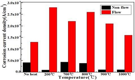
Variation of the corrosion current densities with annealing temperatures under non flowing and flowing condition
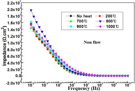
Figure 8 compares the impedances with annealing temperatures in the absence of flowing seawater. The impedances indicated at 0.01Hz by the annealing heat treatment in the absence of flowing seawater exhibit considerably higher values than that of non-heat treatment, whereas the impedances at 105Hz show similar values.
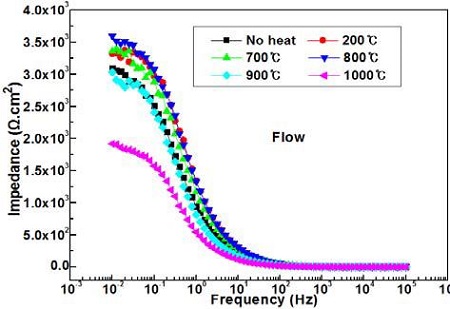
Figure 9 shows the variation of the impedances with annealing temperatures in the presence of flowing seawater. The impedances at 105Hz show similar values regardless of the annealing temperature, but the impedances at 0.01Hz exhibit considerably different values. For example, the impedances of the samples annealed at 1000 °C show the lowest value, and the samples annealed at 900 °C follow the heating temperature of 1000 °C; these values are lower than those of the non-annealed samples. On the other hand, the impedances of the other annealing temperatures show higher values than that of the nonannealed sample.
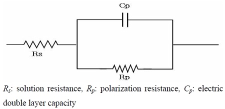
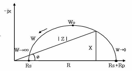
Measurements of the impedance can generally be used to estimate the corrosion resistance of numerous corrosive materials. Moreover, when a corrosive metal is immersed in seawater, the boundary between the seawater and metal surface builds up an equivalent circuit composed of the solution resistance, polarization resistance and electric double layer capacity. Figure 10 shows a typical equivalent circuit diagram [12]. In addition, a Cole-Cole plot of Figure 11 can be obtained by parameter of Hz based on the equivalent circuit of Figure 10. A theoretical equation for solution resistance (Rs) and total polarization resistance Rt, (Rt = Rs + Rp) is given in Equation (1).
| (1) |
As shown in Figure 11, Wo indicates a medium value of W (Hz) between W→∞ and W→0, and if W (Hz) is increased infinitely, the total resistance (Rt) can be indicated as Equation (2), i.e.,
| (2) |
On the other hand, if W (Hz) is approximated to almost zero, the total resistance (Rt) can be obtained as Equation (3), i.e.,
| (3) |
Not that W (Hz) cannot give practically infinite or zero values. Thus, in this experiment, a range of Hz from 0.01Hz to 105 Hz have been applied to approximate the values of Rt and Rs. For example, the values of Rt and Rs are equivalent to the impedance values measured at 0.01 Hz and 105 Hz, respectively.
Therefore, by Equation (1), (2), and (3), the impedances at 0.01Hz and 105Hz means the polarization resistance and solution resistance respectively. In addition, it is generally accepted that the corrosion resistance increases with increasing polarization resistance, i.e., impedance. Therefore, it can be assumed that the higher impedance at 0.01Hz indicates better corrosion resistance.
Figure 12 compares the impedances with annealing temperatures in the presence and absence of flowing seawater. The values of impedance in the presence of flowing seawater increased compared to the non-flowing condition. In particular, the highest impedances can be observed in the samples annealed at 800 ℃ irrespective of the flowing condition of seawater. In the flowing condition, dissolved oxygen can also diffuse easily to the surface, making it easier to form an oxide film. Therefore, the oxide film is believed to play an role in the impedance. Therefore, the impedance of the flowing condition indicates a higher value than that of the non-flowing condition.
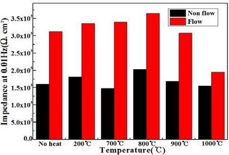
Comparison of the impedances with annealing temperatures in the presence and absence of flowing seawater
Thus, corrosion resistance of the cupro-nickel alloy can be improved slightly by an annealing heat treatment.
4. Conclusions
The Cu-10%Ni alloy has been annealed, and the effects of annealing on its corrosion resistance have been investigated using electrochemical methods, such as measuring the corrosion potential, anodic polarization curves and impedance behaviors. The corrosion resistance increases with annealing compared to the no heat treatment in the absence of flowing seawater. In particular, the sample annealed at 200 ℃ exhibits the best corrosion resistance. The impedance in the presence of flowing seawater show higher values than in the absence of flowing seawater. Furthermore, the highest impedances can be observed at an annealing temperature of 800 ℃, irrespective of the presence of flowing seawater. Consequently, it is suggested that the corrosion resistance in a severely corrosive environment can be improved by an annealing.
References
- D . P. Cox, “Copper resources in ency clopedia of materials science and engineering”, 2, M. B. Beven Ed, Dergamon Press and the MIT Press, p855-859, (1986).
- T. Cunningham, “Marine coating inspection program”, 97-1, NACE International Houston, Texas, (1997).
- T. Cunningham, “The Marine Enviroment”, Version 97-1, NACE International Houston, Texas, (1997).
- Cathelco, Antifouling System Operation Manual, Marine house Hipper Street South, HULL SB-395, (1976).
- Marine Fouling and Its Prevention, U. S. Naval Institute, Annapolis, Md, (1952).
- H. C. Flemming, and G. G. Geesey, “Biofouling and biocorrosion in industrial water system”, Proceedings of International Workshop on Industrial Biofouling and Biocorrosion, p13-14, (1990).
- Standard Method for Testing Antifouling Panels in Shllow Submergence, ASTM, D 3623-78a, (1993).
- R. W. Cahn, P. Hassen, and E. J. Kramer, “A comprehensive treatment, structure and properties of nonferrous alloys”, Materials Science and Technology, 8, VCH p234, (1996).
- E. G. West, Copper and Its Alloys, Ellis Horwood Ltd., Halsted Press, USA, p567, (1982).
- B. Todd, and P. A. Lovett, Marine Engineering Practice: Selecting Materials for Seawater Systems, Technical Report 7, Institute of Marine Engineers, London, UK, p789, (1976).
- K. M. Moon, J. P. Won, D. H. Park, S. Y. Lee, J. A. Jeong, M. H. Lee, and T. S. Baek, “Evaluation on the polarization characteristics of embedded steel bar of mortar specimen (W/C:0.4) with passing aged years”, Corrosion Science and Technology, 13(20), p20, (2014), (in Korean).
- K. M. Moon, Practical Electrochemistry, Edited by Hyou Sung Co. Ltd, p187, (1999).


