The Performance Evaluation of a Hydraulic and Magnetic Clamp Device Manufactured to Transport with Safety the Curved Steel Plate Required for Shipbuilding
Copyright © The Korean Society of Marine Engineering
This is an Open Access article distributed under the terms of the Creative Commons Attribution Non-Commercial License (http://creativecommons.org/licenses/by-nc/3.0), which permits unrestricted non-commercial use, distribution, and reproduction in any medium, provided the original work is properly cited.
Abstract
As a new technical approach, a hydraulic and magnetic clamp device was attempted to realize a magnetic clamp crane system that uses 8 simultaneously actuating individual hydraulic cylinders. Through this approach, a Sr type of ferritic permanent magnet (SrO ㆍ 6Fe2O3), not the previously employed electro-magnet, was utilized for the purpose of lifting and transporting the heavy weighted and oversized curved steel plates used for manufacturing the ships. This study is aimed at manufacturing and developing the hydraulic magnetic clamp prototype, which is composed of three main parts – the base frame, cylinder joint, and magnet joint – in order to safely transport such curved steel plates. Furthermore, this research was pursued to conduct a performance evaluation as to the prototype manufacture and acquire the planned quantity value and the development purpose items. The most significant item for a performance evaluation was estimated for the magnetic adhesive force (G) and in this process, a ferritic permanent magnet (Sr type) with 3700~4000 G of residual induction (Br) and 2640/2770 Oe of coercive force (Hc) was utilized. In addition, other relevant items such as hoist tension (kN), transportation time (sec), and the applied load (Kgf) exerted on the hydraulic cylinders were also evaluated in order to acquire the optimum quantity value. As a result of the evaluation, the relevant device turned out to be suitable for safely transporting the curved steel plates.
Keywords:
Hydraulic and magnetic clamp, Curved steel plates, Performance evaluation, Ferritic permanent magnet, Residual Induction, Coersive force, Adhesive force, Applied load, Base frame, Hydraulic cylinder1. Introduction
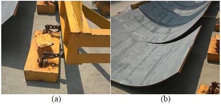
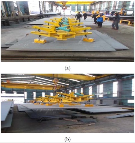
Recently, shipbuilding is being manufactured under the process of welding, assembling and producing the numerous flat and curved blocks, and most of ship yards are being faced with depending on outside suppliers’ fabrication for these many blocks by considering their process schedule. Especially, for the case of the general magnetic crane to lift and transport the huge steel sheets, a necessity of the acquisition for self-safety is being required in the aspect that industrial safety accidents occasionally happen as transporting the curved steel plates, due to looseness of fixed chain parts connected with magnetic. In addition, in case of the mentioned general magnetic crane, it has some limitation for magnetic application in terms that 'electro-magnet' are mostly used where magnetic function only plays a role as current is running (refer to Figure 1 and 2).
In order to acquire the stability related to the above case, it is needed to escape from the previous engineering method and adopt the more reliable one. That is, it is recommanded to introduce the crane of 'hydraulic and magnetic clamp' to transport the gigantic weight object by utilizing the dynamic behaviors of hydraulic cylinders with the application of permanent magnet to have more reliable magnetic characteristics. As adopting the new concept of magnetic crane, a device system is composed of three factors such as base frame, magnetic joint and hydraulic joint. Since the same tension is applied onto the hydraulic joints, as transporting the massive object of curved steel plate, the accident to drop the weight object might be prevented with the benefit of magnetic property in magnetic material reliable. In the aspect that the same tension force is applied, a hydraulic device means a hydraulically-balanced one.
For the case of the 'hydraulic and magnetic clamp' crane to safely transport the massive curved steel plates for shipbuilding with high adhesive force and suitable coercive one, the key component is a magnetic material(permanent magnet) composing the clamp device, connected with the hydraulic cylinder. Here, a term of magnetic material means a total material having the magnetic property in physical concept, and a specific material that can be actually applied to machinery, equipment and component requiring the magnetic property in engineering concept.
A magnetic material can be devide into two parts in terms of magnetic characteristics. One is a 'hard' magnetic material with a high coercive force (Hc) and a suitable residual induction (Br). The other is a 'soft' magnetic material, a high permeability material with high permeability and low coercive force, showing a high variation of magnetization as to outer magnetic fields. Permanent magnet belongs to the hard magnetic material and high-permeability material does to the soft magnetic one. The above mentioned magnetic materials (hard, soft) are being under such a variety of applications in most of industry fields [1][2].
Apart from the above magnetic materials, there is a electro- magnet where magnetic function is exhibited during current is running. The electro-magnet is a sort of magnet that magnetic field is formulated only as current is running, and it actually requires the artificial, extraneous factors. On the other hand, it has a weak point to lose magnetic function due to the disappearance of magnetic field magnetic in case of a short circuit or sudden break [3]. In case of the general magnetic crane, most of electro-magnets are being utilized. Even though the ship yards could apply the new concept of transporting crane by using the permanent magnet with excellent magnetic characteristics and efficiency, they are facing the lack of responding policy for the case owing to cost reduction and shortening of process time.
For this study, the supervising and participating enterprise was purposed to manufacture the prototype of ‘hydraulic and magnetic clamp’ for the new concept of magnetic crane through the mutual cooperation for the purpose of transporting the curved blocks with safety. In comparison to the previous magnetic crane, the permanent magnet of high performance with superior magnetic property was connected with both base frame and cylinder joint to make sure that a hydraulic and magnetic clamp for transporting is manufactured. In this process, a hydraulic-balancing mechanism that the same tension force is applied simultaneously was introduced to acquire the stable actuation and performance. In addition, prior to the development, the prototype was attempted to be visualized through the concept and detail design (refer to Figure 3).
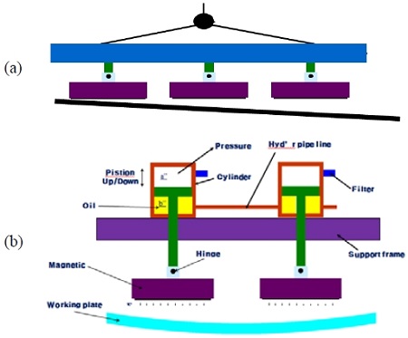
A schematic diagram for comparison of present-purposed hydraulic magnetic clamp device (b) with the previous clamp device (a)
The purpose of this study is to manufacture and develop the ‘hydraulic and magnetic clamp’ device for the purpose of safely transporting the huge curved steel plates applied to shipbuilding. Most of all, this study aims at realizing the performance evaluation as to the manufactured prototype and acquiring the quantitative valve scheduled for development. Especially, with respect to the magnetic adhesive force (G), the most significant item to evaluate, the decision and application of optimum permanent magnet was in consideration. Furthermore, the main items to evaluate such as a hoist tension (KN), a transportation time (sec) and a load applied to the cylinder (kgf) were estimated for the performance test.
2. Test Method and Procedure
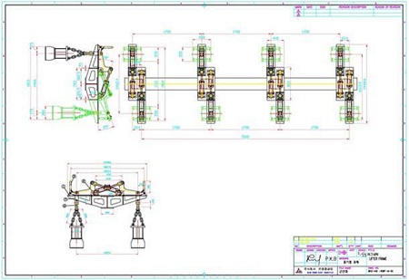
For this study, a ‘hydraulic and magnetic clamp’ device system composed with base frame, magnetic joint and hydraulic joint was manufactured in order to get out of the previous simple magnetic crane and develop the new concept of magnetic clamp crane to transport with safety the massive curved steel plates for shipbuilding. First of all, the design operation for a hydraulic-balancing device where the same tension is simultaneously applied to the 8 hydraulic cylinders was performed. In this process, the initial concept design and the detailed design were prepared to visualize the purposed prototype. The detailed drawing for a ‘hydraulic and magnetic clamp’ is shown in Figure 4. After design operation, structural analysis was conducted in order to review a structural stability and any structural defects were not found.
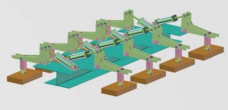
For 3-D modelling, a modelling operation was performed for visualization and implementation of a hydraulic-balancing device where the same tension is applied onto the 8 hydraulic cylinders, by using 3-D modelling tool (3D-MAX). In case of the new concept prototype, a device system was composed of base frame (blue), magnetic join t(yellow) and hydraulic joint (green) and a schematic diagram for the 3-D modelling is shown in Figure 5.
For this study, investigation for the performance test was performed by focusing on the hard magnetic material (permanent magnet) that is able to transport the heavy curved blocks, maintaining high residual induction and excellent coercive force. For the permanent magnet, a ferrite type of permanent magnet (Sr ferrite magnet, SrO ㆍ 6Fe2O3) to maintain high residual induction and coercive force was utilized by considering economics and reasonableness of project cost.
With respect to the purpose values for performance, the quantitative value and data as to the individual evaluation items are mentioned in Table 1. As reviewing the evaluation items in Table 1, it can be found out that a magnetic adhesive force (G) takes the most portion (40%) among the evaluation items and belongs to the most significant one. For this response policy, the performance analysis was entrusted to the outer specialized research agency and the result was considered as the standard reference for performance test. Especially, a review for the kind, characteristics and application was necessary for revealing the adhesive force of 8.2G, in comparison to the previous one (6G).
For the case of the transport time, compared to the previous one, there was no variation in the purpose value. In case of the hoist tension, to acquire the value of 147kN (14.7Ton) that is more increased than ever was scheduled. Furthermore, for this study, a ‘hydraulic and magnetic clamp’ device showing the 150kN (15Ton) of the hoist tension was scheduled for acquiring the reliability of project output. In relation to objectiveness for the prototype’s stability, the performance evaluation as to the manufactured prototype was performed under the supervision of an outside agency (KOLAS) charging the performance test.
3. Test Analysis and Consideration
3.1 Manufacturing of a hydraulic, magnetic clamp
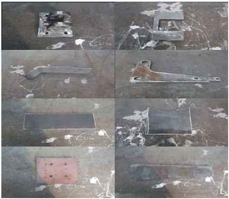
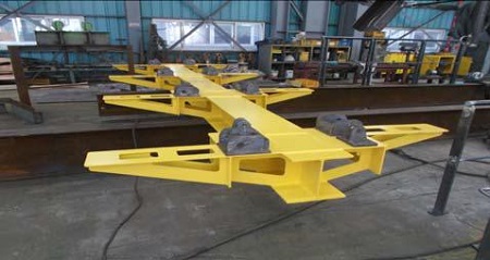
For this study, a ‘hydraulic and magnetic clamp’ prototype is mainly composed of cylinder joint, base frame and magnet joint, and both hydraulic cylinder and permanent magnet are the main components. Hydraulic cylinders (8EA) were prepared to obtain from a domestic specialized company by means of self-purchase in accordance with the detailed design. For the permanent magnet, it was manufactured by importing the raw material from the abroad and fabricating with respect to the detailed drawing. In addition, the remarkable point as to the permanent magnet is that the cost of permanent magnet used for some special applications is very expensive in terms that some chemical element (Here, Co) in the magnet globally exists in some limited country. Therefore, a review for the material items (especially, cost) in the project is generally required. With respect to the base frame that formulates the structure of system, the main outfittings composing the base frame were manufactured by means of CP (cutting plan) as shown in Figure 6. In addition, a view of the base frame playing a role to sustain the whole load of the prototype, as a entire body, is shown in Figure 7.
In relation to the permanent magnet, a key component in a ‘hydraulic and magnetic clamp’ device, Sr(Strontium) ferritic permanent magnet was utilized and the relevant physical properties are shown in Table 2. Especially, for the residual induction (Br) and the coercive force (Hc), the Sr ferritic permanent magnet (SrO ㆍ 6Fe2O3) normally possesses a Br (G) of 3700 ~ 4000 Gauss and a Hc (Oe) of 2640/2770 Oersted. As shown in Table 2, the average coercive force (bHc) of the Srferritic magnet is 2500 ~ 2640 Oe and relatively, the inherent coercive force (iHc) is 2600 ~ 2770 Oe. This permanent magnet is in such a variety of applications for the hardmagnetic material in terms that it has both residual induction and coercive force that are quite suitable, compared to the original cost, in consideration of economic aspects. On the other hand, the Sr ferritic permanent magnet is often compared with Sm, or Nd type of permanent magnet that has a supreme residual induction and an excellent coercive force but is very expensive.
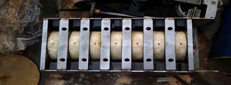
The view of internal component in the relevant permanent magnet is shown in Figure 8 and 9. There is SS400(normal structural rolling steel) between cylindrical ferritic permanent magnets and the SS400 as a ferro-magnetic substance plays a role of partition being in contact with permanent magnets. For the case of side plate, the SS400 was applied for the same case. Especially, the SUS304, an austenitic stainless steel (non-magnetic substance), was utilized to ensure that it is used for the bottom plate of the Sr ferritic permanent magnet body.
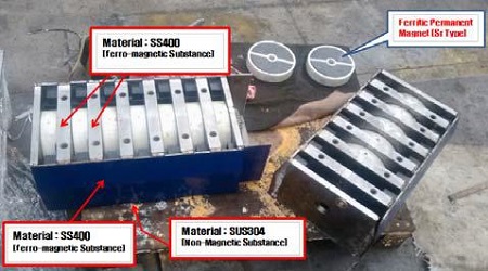
Image to show the relationship between the individual components and the relevant materials used for the permanent magnet body
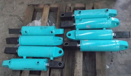
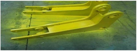
For the hydraulic cylinder as the main component of a ‘hydraulic and magnetic clamp’ device, the relevant system was manufactured to make sure that 8 cylinders simultaneously conducts the stroke of compression and tension, maintaining a hydraulic-balancing state. The view of hydraulical cylinders (8EA) is shown in Figure 10. For the hydraulic cylinder joint, the hydraulic line (4set/ line, 2EA/ 1set) was installed to ensure that 8 cylinders simultaneously actuate being in harmony with together. In case of the ‘magnetic arm unit’ to play a role of connecting the hydraulic cylinders over the base frame, it is composed of two side plates and one rib plate, which is shown in Figure 11.
3.2 Execution of performance test and acquisition of quantitative value as evaluated
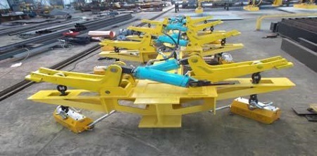
The above main components such as base frame, permanent magnet and hydraulic cylinder were mutually connected and assembled in accordance with the detailed drawing. And then, the purposed prototype was manufactured and its view is shown in Figure 12. After manufacturing the prototype, the test opeation was conducted several times to ensure that a normal operation on the system is going on. In this process, the internal review and the repair work were carried out in consideration of several variables such as a state of hydraulic line, a hydraulic-balancing state, an option of normal operation and a magnetic adhesive force state, etc. And then, the performance test was performed under the supervision of an outer expert. For the performance evaluation, it was conducted as to the 5 items mentioned in chapter 2 under the supervision of KOLAS agency.
For the 5 evaluation items (curve ratio, adhesive force, hoist tension, transportation time, cylinder load), individual performance test was performed. First of all, for the curve ratio (mm) of the curved steel plate, a curve ratio of 160mm exceeding the purpose value (131mm) was actually acquired. As measuring the curve ratio, one side of steel plate was fixed by using of jig and the other side was measure by a measuring tool. In case of transportation time (sec), the running time from ‘A site’ to lift the curved steel plate to ‘B site’ to drop the plate after the transportation upto 50M was measured by using of stop watch. A value of 1min 21sec(81sec) was obtained, showing the data to minimize the purpose one (120sec).
With respect to the cylinder load (kgf), the load (kgf) applied onto the individual cylinder was measured as the 8 cylinders are balanced under the simultaneous execution. In this process, the value of 1,250kgf near the purpose one (1,200kgf) was obtained on the basis of the tension applied onto the hoist. For the case of hoist tension (kN), the value of 150kN near the purpose one (147kN) was obtained by transporting with safety the curved steel plate with weight of 15ton and thickness of 21mm. In addition, in relation to the most significant item, a magnetic adhesive force (G), it was measure by using of gauss-meter as the permanent magnet was instantly adhering the curved steel plate. In this process, the adhesive force of 8.7G was obtained most of all.
3.3 Consideration on the adhesive force of magnet and relevant magnetic characteristics
As shown in B-H curve (B : magnetic flux density, H : intensity of magnetic field), a residual induction (Br) is supposed to remain when the magnetic field returns to '0' after magnetization of the magnetic substance (refer to Figure 14 (a)). Therefore, if the substance having high residual induction (Br) is used, the strong permanent magnet might be obtained, which means that the significant requirement for the permanent magnet is to have a high coercive force (Hc) [4][5]. Especially, the magnetic current density (B) occurring the magnetic substance shows the different value as to the previous state of magnetization, even though the intensity of magnetic field (H) is the same. The typical hysteresis loop showing the type as to the applications(for magnet and for magnetic core) is indicated in Figure 14 (b)[6][7].
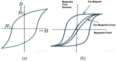
The diagram of typical hysteresis loop; (a) B-H curve, (b) types of various hysteresis loops (for magnet and magnetic core)
Actually, a permanent magnet is one that is manufactured for the purpose of using the residual induction of the magnetized magnetic substance, and the typical permanent magnet is to have a high coercive force (Hc) and a suitable residual induction (Br). In relation to the adhesive force of permanent magnet, the priority to obtain high adhesive force as performance test is to use the magnet having a high residual induction (Br, G). In addition, the used permanent magnet is to have an excellent coercive force (Hc, Oe) as a main property.
For this study, an optimum permanent magnet was attempted to decide in order to perform the target of quantitative data as to the adhesive force (G), the key one among evaluation items. In this aspect, the study mainly focused on the adhesive force (G) of the Sr ferritic magnet to transport with safety the heavy curved steel plates, maintaining high adhesive force and excellent coercive force.
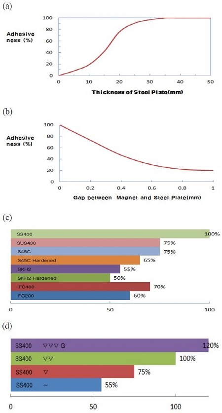
As shown in Figure 15, the correlation between the adhesive force and extraneous variables (steel plate thickness, gap, material and surface roughness) was investigated and the results are found. For the steel plate thickness, the coercive force showed the tendency to increase along the point of inflection in the gradual curve as the thickness of the steel plate is increased. On the other hand, in case of gap (between steel plate and permanent magnet), the coercive force was decreased as the gap was increased. As to material, the coercive force showed the tendency to increase as follows; middle corbon steel (0.45%C, S45C) or ferritic stainless steel (SUS430) < the structural steel (SS400). For the surface roughness, a high property of adhesiveness was mostly shown on the smooth surface with having no defects.
Considering the magnetic property and economic aspect for the permanent magnet which belongs the key componet of a 'hydraulic and magnetic clamp' device, a definate review was necessary for the type, physical property, application and actual cost of individual permanent magnets.
A permanent magnet, namely a hard magnetic material can be mainly divided into as follows; AlNiCo (Fe-Co-Ni-Al alloy), a ferrite type, a rare-earth type. AlNiCo is an alloy that Al, Ni and Co were added into Fe base metal and it can be applied to variable situations. It is also used for a variety of applications since it has an excellent temperature characteristics. On the other hand, it has a weak point to have a lower coercive force (Hc), which indicates that its magnetic force relatively drops when the action of attaching and detaching goes on with repeat.
A ferritic magnet is classified into two types such as Sr ferrite type (SrOㆍ nFe2O3) and Ba ferrite type (BaOㆍ nFe2O3). The Sr ferrite type has the higher coercive force and physical property, compared to the Ba ferrite. The ferritic magnet is generally used for a normal speaker (Ba ferrite), a speaker with high performance (Sr ferrite), the sensor, the cooling-fan motor. The ferritic magnet is manufactured by the powder metallurgy that the magnetic podwer is processed by method of formation and sintering. The various magnets with high efficienty are shown in Figure 16[8][9].
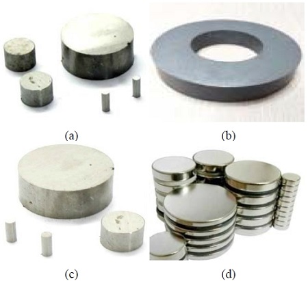
Figures to show individual shapes of relevant permanent magnets; (a) AlNiCo, (b) Ferrite, (c) Sm-Co, (d) Nd-Fe
With respect to the rare-earth magnet that was recently developed for the high efficiency of permanent magnet, it has a very excellent magnetic property and shows an supreme property of coercive force and residual induction. The main item of the rare-earth magnet was the Sm-Co, but the Nd-Fe magnet was recently developed due to the method of power metallurgy( 1~10)㎛. The Nd-Fe is now globally absorbing public attention because of its excellent, supreme magnetic characteristics. Since Co, a main element in the Sm-Co, exists in some rare place on the earth, the Nd-Fe is taking the place of it. This permanent magnet is being used for a light motor, the sensor, the medical and electronic, etc. [10].
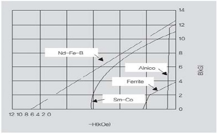
Considering the coercive force(Hc), it is known that the relevant force is increased as follows; AlNiCo< ferrite< Sm< Nd. On the other hand, it seems like the residual induction is increased as follows; ferrite< AlNiCo< Sm< Nd in terms that the residual induction of AlNiCo is higher that that of ferrite. The relative comparison as to the coercive force and the residual induction of the permanent magnets is shown in Table 4[11].
From the objective point of view, for the case of AlNiCo, it has a weak point that it is easily magnetized by the outer magnetic field because of high residual induction while it has less coercive force, which explanes that demagnetization occurrs with ease in AlNiCo. Considering the magnetic permeability is the magnetic flux density (B) devided by the intensity of magnetic field (H), AlNiCo might be the permanent magnet with high permeability ironically. The curve of demagnetization characteristics in the permanent magnet is shown in Figure 17 and it can be inferred that AlNico might be easily demagnetized in comparison to other permanent magnets.
This study is focused on manufacturing and developing the ‘hydraulic and magnetic clamp’ device for the purpose of safely transporting the huge curved steel plates applied to shipbuilding. In addition, this study aimed at realizing the performance evaluation as to the manufactured prototype and acquiring the quantitative valve scheduled for development. The prototype was mainly cylinder joint, base frame and magnet joint and the hydraulic cylinder and permanent magnet were the main component. In this case, the Sr ferritic permanent magnet was selected for the suitable magnet considering the efficiency and the economic aspects.
Especially, a ‘hydraulic and magnetic clamp’ device was manufactures by using the permanent magnet, no the previous electro-magnet so as to transport the curved blocks with safety and prevent the possible safety-accident. The certificate for a patent as to the manufactured prototype is shown in Figure 18.
In future, in case that the following product is introduced in the 50 block-manufacturing companies, it is expected to bring out the improvement of productivity and the environmental variation whatever. This hydraulic and magnetic clamp device might is also expected to dedicate to the stability of the enterprises using the magnet devices. Furthermore, it will be in such a variety of applications for the crane to transport the curved blocks in the shipyards.
With respect to the recent magnetic tendancy, it is well known that both Europe and USA have the advanced magnetic technology, compared to that of the domestic. The technical flow might be mainly divided into two parts such as a ‘energy-conserving’ type, and a ‘automation device’ type. For the case of a ‘energy-conserving’ type, it is introduced for the cost reduction as the concept that the permanent magnet and the electro-magnet is combined. For a ‘automation device’, it belongs to the case that the investment cost is increased for the productivity and the automatic system and sophisticated technology come in contact with the magnet.
4. Conclusions
In relation to the performance evaluation of a ‘hydraulic and magnetic clamp’ device to transport the curved blocks for the shipyards, the major conclusions drawn from the study are as follows:
- (1) With respect to the magnetic adhesive force(G), the significant evaluation item in the ‘hydraulic and magnetic clamp’ prototype, the Sr ferritic permanent magnet (SrO ㆍ 6Fe2O3) showing a residual induction (Br) of 3700~4000G, an average coercive force (bHc) of 2500~2640Oe and an inherent coercive force (iHc) of 2600 ~ 2770Oe was used for main magnetic property in the permanent magnet and applied for the performance evaluation.
- (2) As conducting the performance evaluation as to the ‘hydraulic and magnetic clamp’ prototype composed of base frame, cylinder joint and magnetic joint, 8.7G of the magnetic adhesive force (G) was acquired and actually, the quantative value relatively higher than that of domestic technology (6G) was shown.
- (3) With respect to the performance test to adhere and transport the heavy curved steel plates by using the ‘hydraulic and magnetic clamp prototype, the quantatave values such as 150kN of the hoist tension, 81sec of the transportation time and 1250Kgf of the cylinder load were acquired and the performance value for the development purpose was satisfied.
- (4) For the case of this prototype, the process of compression and tension was simutaneously conducted by maintaining the hydraulic-ballancing, connected with the Sr ferritic permanent magnet. In addition, it was turned out that
this device could be used for the one to transport with safety the curved steel plates applied to the fabrication of ships and in future, it would be in such a variety of applications for the relevant areas.
Acknowledgments
This research was conducted by the assistance of a human resources training project for regional innovation, the Korea Research Foundation(No.2013H1B8A2023237) and a Core R&D Project for Industry-University-Research Co-work, Jeonbuk Technopark.
References
- B. D. Cullity, Introduction to Magnetic Materials, Tokyo, Japan, (1972).
- W. F. Smith, Princiles of Materials Science and Engineering, Mcgraw-Hill, (1990).
- C. S. Barrett, W. D. Nix, and A. S. Tetelman, The Principles of Engineering Materials, Prentice-Hall, (1973).
- K. J. Strnat, “Rare-earth magnets in present production and development”, Journal of the Magnetism and Magnetic Material, 7(1), p351-360, (2008).
- H. K. Cho, Advanced Materials and Alloys, Kyung Buk National University. Press, (1988).
- E. A. Nesbitt, and J. H. Wernick, Rare Earth Permanent Magnets, Academic Press, New York, (1973).
- J. P. Schaffer, A. Saxena, S. D. Antolovich, T. H. Sanders, and S. B. Warner, The Science and Design of Engineering Materials, Richard D. Irwin, Inc, (1995).
- R. L. Comstock, Introduction to Magnetism and Magnetic Recording, (1999).
- K. Helmut, “Micromagnetism of hard and soft magnetic materials”, Journal of the Korean Magnetics Society, 5(5), p366-371, (1995).
- L. L. Hench, and K. West, Principles of Electronic Ceramics, John Wiley & Sons, Inc, (1990).
- Metals Handbook, 9th ed, 3, ASM International, Materials Park, Ohio, (1980).

