Design factors for ensuring the structural safety of fire monitors on ships
Copyright © The Korean Society of Marine Engineering
This is an Open Access article distributed under the terms of the Creative Commons Attribution Non-Commercial License (http://creativecommons.org/licenses/by-nc/3.0), which permits unrestricted non-commercial use, distribution, and reproduction in any medium, provided the original work is properly cited.
Abstract
Owing to the increasing size of modern vessels, the operating pressure of fire monitors has increased to cover larger spraying areas and distances in the event of fire, leading to more frequent occurrences of damage. This study examines the optimal design factors for preventing damage to fire monitors on ships, even under high-pressure operating conditions. This study focused on two main aspects. First, the pipe thickness is optimized to prevent damage under high-pressure conditions. Second, the force on the flange bolts that connects the pipes to the spray nozzles is evaluated, ensuring that they can withstand high pressure. The performance of these bolts plays a critical role in preventing damage. Through a systematic analysis, this study examines how these design factors affect the performance and durability of fire monitors and provides design guidelines for damage-free operations. The ultimate goal was to enhance the stability and reliability of fire monitors for effective fire suppression on ships.
Keywords:
Fire monitors, Pipe thickness optimization, High-pressure conditions, Flange bolts, Structural safety1. Introduction
This study aimed to investigate the optimal design factors that prevent damage to fire monitors on ships, even under high operating pressures[1]. With the increasing size of modern vessels, fire monitors are required to cover larger spraying distances and areas in the event of a fire[2][3]. As a result, the operating pressures of fire monitors have been increased to improve their performance, leading to more frequent damage. Previous studies on fire monitors have focused on predicting spraying distances and evaluating structural safety. However, this study is original in terms of the design factors. This study focuses on two main aspects. First, the pipe thickness was optimized to withstand the resulting loads and thereby prevent the damage caused by high operating pressures[4].
Second Evaluation of Force on the Flange Bolts. The study also examined the force acting on the flange bolts that connect the pipes to the spray nozzles, ensuring that these bolts can endure high pressure without failure. The performance of these bolts is critical for preventing damage[5]. This study systematically analyzes the impact of these design factors on the performance and durability of fire monitors and provides design guidelines to ensure damage-free operation. The ultimate goal was to enhance the stability and reliability of fire monitors for effective fire suppression on ships.
2. Modeling and Analysis Conditions
2.1 Model
The analysis model used was a 150A fire monitor, where the nozzle section was not modeled separately, and only the piping section was considered in the analysis. The fire monitor analyzes the features of an elliptical pipe with a thin rod connected horizontally inside the pipe to prevent the pipe from expanding laterally.
The analysis involved increasing the pipe thickness in 1 mm increments from 3 to 12 mm, and a structural analysis was conducted for each increment. Based on the results, if the generated stress was lower than the yield strength of the applied material, the material was considered structurally safe, and the analysis continued under this assumption. Figure 3 illustrates the model used in the analysis.
The material used in the analysis was SUS316. Table 1 lists its mechanical properties.
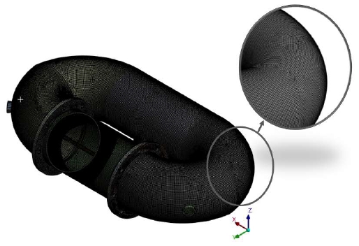
Figure 4 shows the finite element (FE) model used in the analysis. A total of 144,649 nodes and 110,193 elements were analyzed. A structural analysis model was developed using the eight-node structure SHELL281 element, which is an eight-node element.
2.2 Analysis Condition
The analysis conditions were defined by applying a design pressure of 2 MPa to the internal piping of a fire monitor. In addition, all degrees of freedom at the bottom part, where the fire-fighting water inlet was located, were constrained. The analysis was conducted under these conditions.
3. Structural Analysis
3.1 Optimization of Pipe Thickness
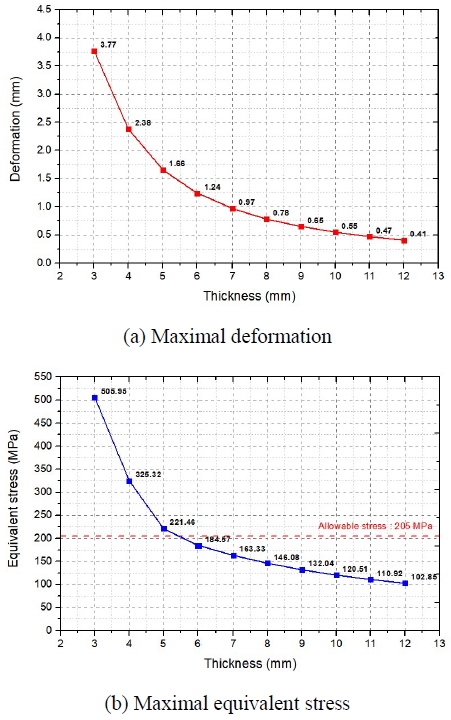
A structural analysis was performed using ANSYS MECHANICAL 2022R2[6]. Based on the analysis results for the optimal pipe thickness, considering an allowable stress of 205 MPa, it is predicted that structural safety can be ensured with a thickness of 6 mm or greater[7]. For a pipe thickness of 6 mm, the maximum deformation was 1.24 mm, and the maximum equivalent stress was 184.57 MPa. As the thickness increased, the stress decreased by approximately 10–20 MPa, and the deformation decreased by approximately 0.1–0.3 mm. Table 2 shows that when the thickness increased beyond 8 mm, the reductions in the deformation and stress became progressively less significant.
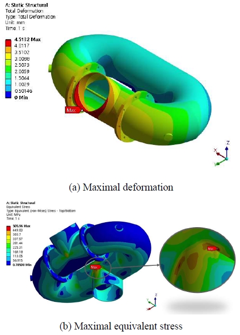
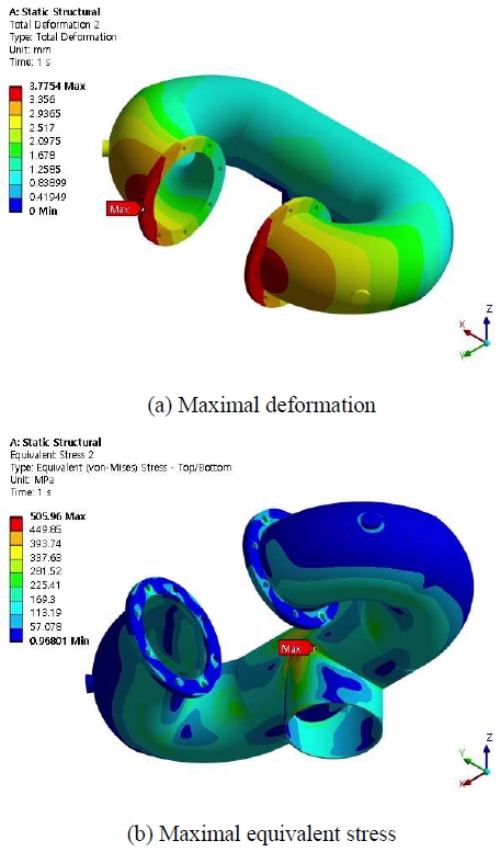
Figure 5 shows the analytical results for the entire model, and Figure 6 shows the analytical results for the piping, excluding the section connected to the nozzle. Maximum deformation occurred in the section connected to the nozzle. Additionally, Figure 6(a) shows that the pipe expands laterally, thereby causing stress, and that significant forces are applied to the flange connection.
As shown from the slope of the graph in Figure 7, when the thickness is increased in 1 mm increments from 3 mm to 7 mm, both the deformation and stress decrease significantly. However, for thicknesses greater than 8 mm, the slope of the graph indicates that the reduction effect becomes negligible with a further increase in thickness.
3.2 Evaluation of the Force on the Flange Bolts
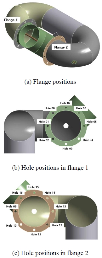
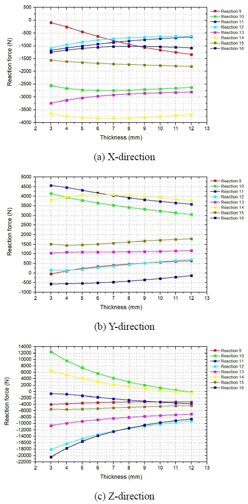
In this section, the reaction forces at the bolts connecting the flanges were calculated to determine the bolt diameter required to select an appropriate bolt size. As mentioned in the previous analytical results, the flange section expands laterally when pressure is applied to an elliptical pipe. Therefore, the selection of the correct bolt size is a critical factor among the design parameters. The fire monitor has two flanges, as shown in Figure 8(a). The bolts applied to flange 1, totaling eight bolts, were numbered from Hole 1 to Hole 8, as shown in Figure 8(b). The bolts applied to Flange 2, with a total of eight bolts, were numbered from Hole 9 to Hole 16, as shown in Figure 8(c).
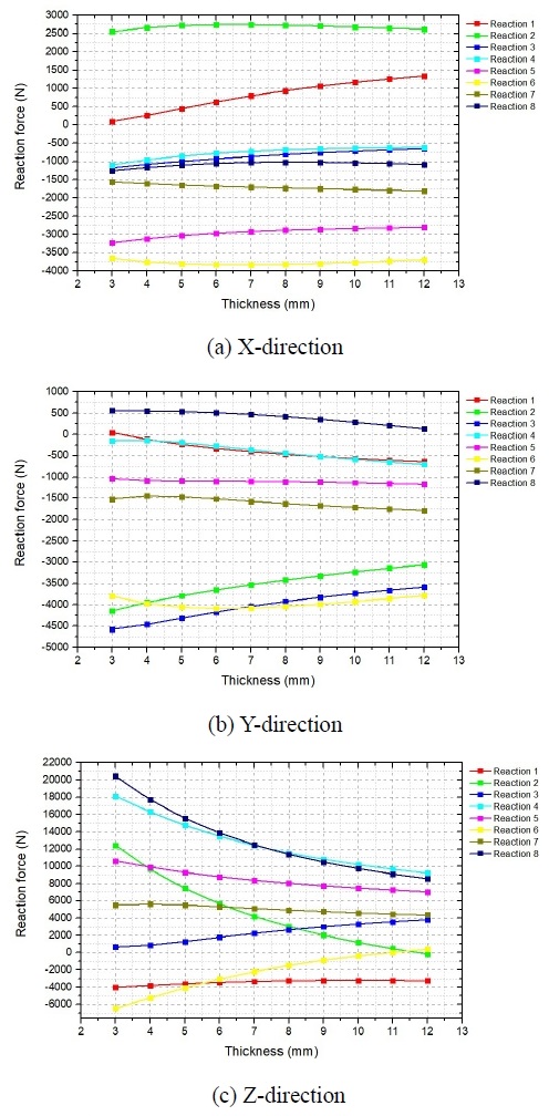
In the previous pipe thickness optimization analysis, the reaction forces generated at the 16 bolt holes were calculated in the X-, Y-, and Z-directions. Owing to the structural characteristics of the bolts, they exhibited high strength in the Z-direction, which corresponded to the tensile loading in this analysis[8]. However, they exhibit significant vulnerability to shear forces acting in the X- and Y-directions. Therefore, the calculated forces in the X- and Y-directions were converted into the resultant forces to calculate the shear force. Based on these results, an appropriate bolt size was selected[9].
The reaction force review results show that the maximum reaction force in the X-direction occurred at Hole 6, with a force of -3,828 N, and the maximum reaction force in the Y-direction occurred at Hole 12 with a force of -4,571 N. The reaction forces exhibited a symmetrical pattern when the absolute values of flanges 1 and 2 were considered.
The shear forces in the X- and Y-directions decreased as the thickness increased; however, the effect of this reduction was minimal. However, the tensile force in the Z-direction significantly decreased as the thickness increased.
The results of the reaction force calculations are presented as graphs for each direction in Figure 9 and Figure 10.
The resulting shear force, represented as the vector sum of the X- and Y-direction reaction forces[10], was approximately 5,963 N. Considering that the shear strength of the bolt was 82 N/mm², a bolt with an area of at least 73 mm² was required to withstand the shear force. Hence, a bolt with a diameter of 10 mm or larger must be used.
Therefore, using M10 or larger bolts is expected to ensure the safety of the nozzle and piping connections.
4. Conclusion
The results of the pipe thickness optimization and bolt specification review, considering the high pressure of fire monitors on ships, are as follows:
- 1) This study conducted an analysis to optimize pipe thickness and assess the structural safety of fire monitors on ships. The analysis model considered only the piping section of a 150A fire monitor with a thin rod horizontally connected inside the pipe to prevent lateral expansion. The pipe thickness was increased from 3 mm to 12 mm in 1 mm increments, and structural analysis was performed for each increment.
- 2) The analysis results confirmed that a pipe thickness of 6 mm or greater ensured structural safety with a decreasing trend in stress and deformation as the thickness increased. This study provides essential foundational data for optimizing pipe thickness for the safe design of fire monitors and offers design guidelines for enhancing safety in high-pressure operating environments.
- 3) Based on the analysis results for optimal pipe thickness, it was predicted that structural safety could be ensured with a thickness of 6 mm or greater. For a pipe thickness of 6 mm, the maximum deformation was 1.24 mm, and the maximum equivalent stress was 184.57 MPa. As the thickness increased, the stress decreased by approximately 10–20 MPa, and the deformation decreased by approximately 0.1–0.3 mm.
- 4) The shear force, represented as the vector sum of the X- and Y-direction reaction forces, was approximately 5,963 N. Considering that the shear strength of the bolt was 82 N/mm², a bolt with an area of at least 73 mm² was required to withstand the shear force. This leads to the conclusion that a bolt with a diameter of 10 mm or larger must be used. Therefore, the use of M10 or larger bolts is expected to ensure the safety of the nozzle and piping connections.
- 5) In future research, fluid performance evaluations will be conducted to predict the spraying distance and area based on the completed design of the fire monitor considering the design factors.
Author Contributions
Conceptualization, Methodology Software, Validation, Formal Analysis, Visualization, Writing-Original Draft Preparation, Software, Validation, Software, Validation, J. S. Jo; Methodology, Writing-Review & Editing, Formal Analysis, Final review, Conceptualization, Supervision, Writing-Review & Editing, Funding Acquisition, J. H. Kim.
References
-
S. -J. Oh, K. -S. Jeon, J. -H. Yoon, and J. -J. Choi, “Performance analysis of ship fire suppression injection system according to shape variables,” Journal of Power System Engineering, vol. 25, no. 2, pp. 40-47, 2021 (in Korean).
[https://doi.org/10.9726/kspse.2021.25.2.040]

- J. -S. Jo, “A study of computational fluid dynamics analysis for the water spray distance of long jet monitor,” Journal of the Korean Society of Industry Convergence, vol. 26, no. 5, pp. 907-913, 2023 (in Korean).
- K. -S. Kim, J. -S. Jo, C. -U. Ryu, C. -K. Lee, and S. -H. Kim, “The structural study of refueling storage tank on helicopter landing area,” 2020 Fall Conference Proceedings of the Korean Society of Manufacturing Technology Engineers, pp. 94, 2020 (in Korean).
-
D. Zeng, X. Wang, K. Ming, C. Yu, Y. Zhang, Z. Yu, J. Yan, and F. Li, “Analysis and optimization design of internal pressure resistance of flexible composite pipe,” International Journal of Pressure Vessels and Piping, vol. 210, 105271, 2024.
[https://doi.org/10.1016/j.ijpvp.2024.105271]

-
Y. Shi, M. Wang, and Y. Wang, “Analysis on shear behavior of high-strength bolts connection,” International Journal of Steel Structures, vol. 11, pp. 203-213, 2011.
[https://doi.org/10.1007/s13296-011-2008-0]

- ANSYS, ANSYS Mechanical User's Guide, 2022R2.
-
S. -G. Han, M. -J. Ha, J. -H. Choi, and J. -S. Kim, “A study on computational fluid dynamics for development of mobile water monitor,” Journal of the Korean Society of Marine Engineering, vol. 41, no. 9, pp. 841-849, 2017 (in Korean).
[https://doi.org/10.5916/jkosme.2017.41.9.841]

- H. Lin, P. Sun, Y. Chen, Y. Zhu, X. Fan and Y. Zhao, “A study on bolt strength calculation for equipment mounted on rolling stock,” 2012 Fall Conference Proceedings of the Korean Society for Railway, 2012 (in Korean).
-
J. -M. Lee, M. -U. Lee, S. -K. Cho, M. -H. Koo, H. -I. Kim, and T. -H. Lee, “Strength Analysis of Bolt Joints for an Open Frame Structure,” Transactions of the Korean Society of Mechanical Engineers - A, vol. 33, no. 8, pp. 819-825, 2009 (in Korean).
[https://doi.org/10.3795/KSME-A.2009.33.8.819]

-
H. Lin, P. Sun, Y. Chen, Y. Zhu, X. Fan, and Y. Zhao, “Analytical and experimental analysis of the shear strength of bolted saw-tooth joints,” European Journal of Environmental and Civil Engineering, vol. 26, pp. 1639-1653, 2022.
[https://doi.org/10.1080/19648189.2020.1726822]


