Finite element analysis of a membrane cell for an artificial gill
Copyright © The Korean Society of Marine Engineering
This is an Open Access article distributed under the terms of the Creative Commons Attribution Non-Commercial License (http://creativecommons.org/licenses/by-nc/3.0), which permits unrestricted non-commercial use, distribution, and reproduction in any medium, provided the original work is properly cited.
Abstract
People are becoming increasingly interested in well-being, which has made scuba diving a popular hobby. Conventional scuba equipment includes an oxygen mask connected to a tank on the back of the diver. However, scuba equipment is heavy and has a time limit; therefore, an alternative membrane type is being developed. In this study, a finite element analysis of a membrane cell for an artificial gill was performed using commercial software. The effects of the horizontal and vertical walls located within the cell were analyzed. The results showed that with a 20 mm horizontal wall, the maximum velocity increased from 0.157 to 0.159 m/s, an increase of 1.3%. In addition, the maximum pressure decreased from 11.4 to 11.3 Pa, a reduction of 0.9%. A membrane cell with 10 vertical walls was also analyzed. The results indicated that the maximum velocity increased by 4.5% to 0.164 m/s and that the maximum pressure increased by 55.3% to 17.7 Pa. These findings may contribute to the development of a detailed design for artificial gill membranes.
Keywords:
Artificial gill, Membrane, Flow analysis, Finite element analysis, Skin scuba, Oxygen tank1. Introduction
As interest in leisure activities grows, skin scuba diving, which enables enjoyment in the ocean, is also gaining popularity. The market for scuba equipment is projected to reach USD 3.4 billion by 2024 and USD 4.0 billion by 2028, with a growth rate of 4.5% [1]. Furthermore, this equipment is essential for life-saving and emergency purposes in ships and airplanes.
Classic scuba equipment, which is critical for breathing, comprises an oxygen gas tank, a hose, and a mask. However, their heavy weight and limited usage time necessitate the development of alternative methods. One of the no-gas tank types uses a polymer membrane. The major component of the new oxygen mask is a membrane that separates oxygen from seawater. Gas exchange is enabled using a membrane without a gas tank.
A membrane can separate certain substances from one side to the other. Separation processes can be categorized as follows: (1) liquid-to-liquid, (2) gas-to-gas, and (3) liquid-to-gas [2]. Liquid-to-liquid separation processes include microfiltration, ultrafiltration, and reverse osmosis, which filter certain materials from one side to the other. In microfiltration and ultrafiltration processes, solid particles are filtered, and in the reverse osmosis process, pure water is obtained from seawater. The second type is called a gas separation process, and the third type, which we use in this study, is called pervaporation. The pore size for this process is smaller than 10 Å.
In our research group, Heo reported several studies on separation mechanisms and experiments [3][4]. A recent study focused on the separation characteristics of exhaled gases prepared using hollow fiber membranes [3]. Another study discussed the effects of a mixed gas using a multistage passive mixer [4]. Moreover, insects can breathe in water using their plastrons, but it is difficult to get sufficient oxygen for humans [5][6].
The ideal structure for this breathing apparatus is an artificial fish gill. If realized, it would allow people to use it autonomously without additional power in a compact helmet equipped with gills. Previous studies have dealt with bio-mimicking approaches, and analyses of the natural organs of fish gills have been performed. In a fish gill, gas is exchanged using the following procedures: (1) dissolved oxygen in river water or seawater is absorbed through the gill, and (2) the carbon dioxide in the body is discharged. To mimic this process, an artificial gill can be created using a gas diffusion polymer film [7]. The difference in the oxygen concentration enables gas diffusion from the water side to the gas side. Lee et al. conducted theoretical modeling of oxygen extraction through an artificial gill, considering consumption by an insect in a limited volume of water [7]. Ning et al. implemented an artificial gill in a photocatalytic water-splitting system that could inhibit hydrogen and oxygen from recombining back to water [8]. Furthermore, Zhen et al. developed a core-shell structured nickel phosphide (Ni2P) photocatalyst and incorporated an artificial gill into a photocatalytic water-splitting system [9]. Nagase et al. attempted to create an artificial gill by using hollow membrane fibers and optimizing the arrangement of hollow fibers to enhance oxygen transfer rates from the water to the air side [10].
However, there are few studies on fluid analysis inside membrane cells. For the effective design of an artificial gill, the velocity and pressure through the cell must be calculated to predict the obtainable oxygen rate. Thus, we believe that it is necessary to perform a finite element analysis of the cell to understand the flow behavior.
Hence, we developed an artificial gill consisting of a membrane, circulation pump, and mask. Membrane cells are crucial components that need to be developed systematically. In this study, finite element analyses were conducted using the commercial software ANSYS. Initially, the impact of a horizontal wall at the center of the cell was analyzed. Subsequently, the effects of the vertical inner walls of the cells were examined. Finally, the obtained flow velocity and pressure values are discussed.
2. Artificial Gill Membrane Analysis
2.1 System Configuration and Analysis Model
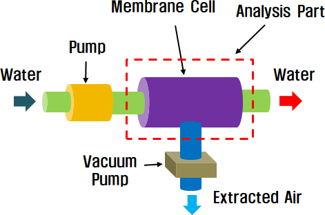
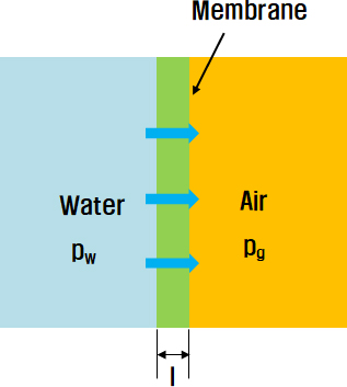
The conceptual design of an artificial gill was composed of a membrane cell, circulation pump, and mask. Figure 1 illustrates the configuration of the system. When freshwater moves from the outside to the membrane cell, air diffusion occurs through the membrane, as shown in Figure 2. The permeation flux J of oxygen through the membrane was calculated using the following equation:
| (1) |
where P is the permeability coefficient, l is the membrane thickness, pw is the partial vapor pressure on the water side, and pg is the partial vapor pressure on the gas side [2]. To continuously obtain a certain amount of air, freshwater should be supplied at the desired value. Therefore, it is essential to calculate the pressure and flow velocity values on each side to design the cell appropriately.
2.2 Analysis Methods
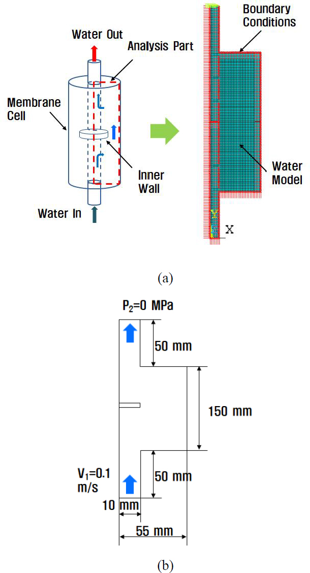
Initially, the effect of a horizontal wall located at the center of the cell was examined. Next, we analyzed the effects of the vertical inner walls that were also present in the cell. The finite element method (FEM) was used for the analysis. A fluid 141 element was selected in ANSYS. A model with a given boundary condition is shown in Figure 3 (a), and its dimensions are shown in Figure 3 (b).
The analytical conditions are listed in Table 1. The membrane cell was cylindrical in shape; therefore, for simplicity of analysis, the membrane cell was modeled two-dimensionally and axis-symmetrically. The material properties of the water used for the analysis are listed in Table 2.
The water flow entered the inlet with a velocity V1 of 0.1 m/s, and after the gas exchange process, it exited through the outlet with a pressure P2 of 0 MPa. The FEM employs three governing equations: (1) continuity, (2) momentum, and (3) energy [12]. The first continuity equation is as follows [11]:
| (2) |
where t is the time and u, v, and w denote the velocities in the x, y, and z directions, respectively. Assuming a steady state, two-dimensional analysis and an incompressible fluid, Equation (2) can be simplified as:
| (3) |
The second momentum equation of the incompressible condition, is as follows:
| (3) |
where g is gravity, p is pressure, and V is the velocity vector. The final energy equation is as follows:
| (4) |
where cp is a specific heat at a constant pressure, k is the thermal conductivity, and Φ is a viscous-dissipation function, defined as:
| (5) |
3. Results and Discussion
3.1 Horizontal Wall Effect Analysis
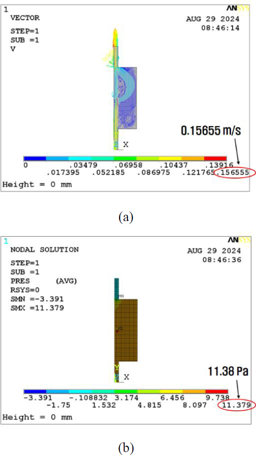
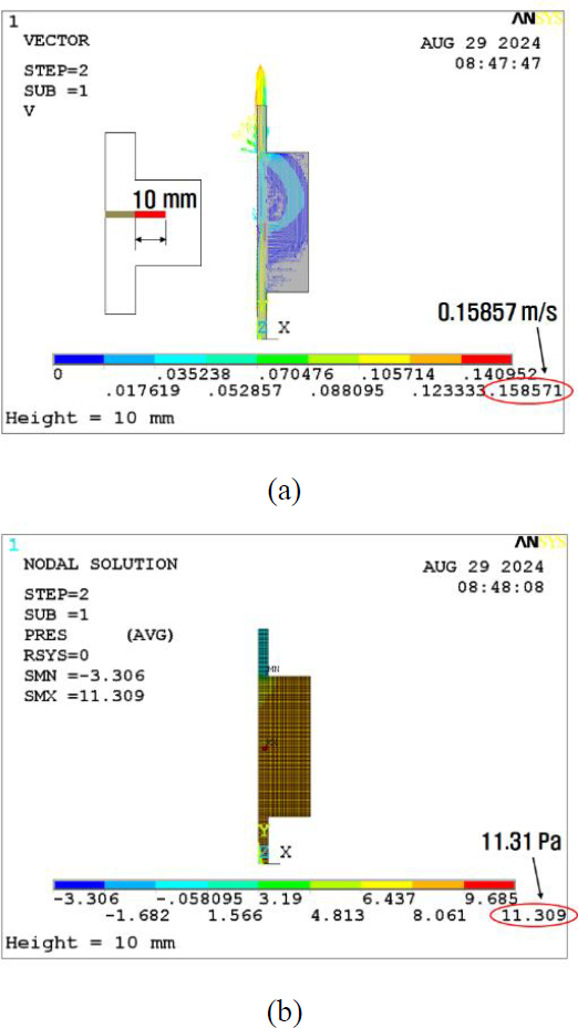
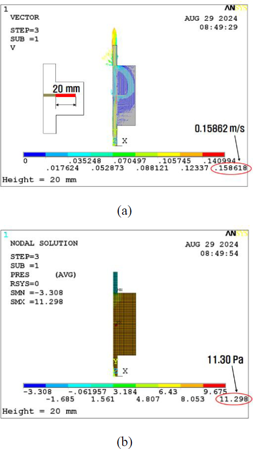
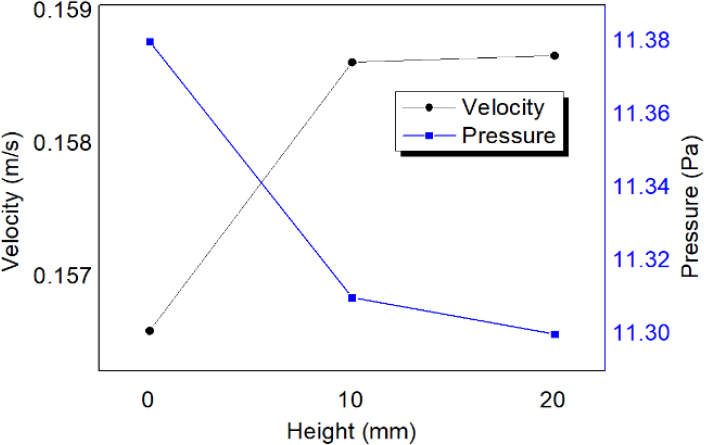
The initial analysis of the basic model for the horizontal wall effect reveals the velocity and pressure results displayed in Figures 4 (a) and (b), respectively. Subsequently, the inner wall thickness was increased to 10 mm. The obtained calculation results for the pressure and velocity are depicted in Figures 5 (a) and (b). At last, the barrier thickness was further increased to 20 mm. The results are shown in Figures 6 (a) and (b). Consequently, the maximum velocity increased from 0.157 to 0.159 m/s, which is a 1.3% increase, as shown in Figure 7. In addition, the maximum pressure decreased from 11.4 to 11.3 Pa, a reduction of 0.9%. The volumetric flow rate Q can be calculated as follows:
| (6) |
where Va is the flow velocity and A is the inlet area [9]. In this analysis, the inlet area and velocity V1 (as shown in Figure 3(b)) were the same; therefore, the volumetric flow rates were also the same.
The analysis results indicate that to maintain the same Q value, the maximum velocity increases, whereas the maximum pressure decreases for increased horizontal barriers.
3.2 Vertical Walls Effect Analysis
Subsequently, the effects of vertical inner walls were analyzed. The actual membrane cell was filled with hollow fiber membranes. Therefore, vertical walls were required for safe performance. In this analysis, 10 vertical walls were modeled and calculated using the procedures described in the previous section.
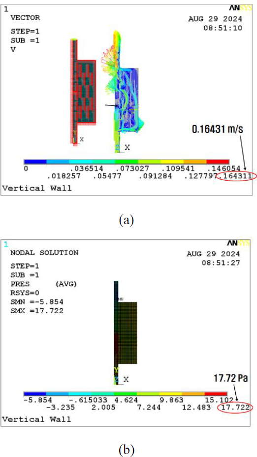
The velocity and pressure results are shown in Figures 8 (a) and (b), respectively. They showed that the maximum velocity increased by 4.5% to 0.164 m/s and that the maximum pressure increased by 55.3% to 17.7 Pa, compared to the basic model of Figure 4 (a). These results imply that many obstacles accompany both the maximum velocity and pressure increases.
There are two main points to this analysis. One is the gas exchange rate, and the other is the pump capacity. To achieve an effective gas exchange rate, a certain velocity range should be maintained. In contrast, a lower pressure is preferred at the point of the pump. Thus, the optimal dimensions need to be determined through proper experiments in future studies.
4. Conclusion
In this study, we conducted a finite element analysis of a membrane cell designed for an artificial gill. The effects of both horizontal and vertical barriers were examined. Initial analyses focused on how the length of the horizontal barrier affects flows, showing that a 20 mm barrier length increases the maximum velocity by 1.3%, from 0.157 to 0.159 m/s. Concurrently, this slightly reduced the maximum pressure by 0.9%, from 11.4 to 11.3 Pa. These results indicate that the maximum velocity increased and that the maximum pressure decreased when the length of the horizontal wall increased.
Furthermore, a membrane cell with 10 vertical walls was analyzed. As a result, the maximum velocity increased by 4.5% to 0.164 m/s, and the maximum pressure increased by 55.3% to 17.7 Pa, compared to the basic model with no wall. These results indicate that the maximum velocity and pressure increase were caused by an increase in the vertical walls. Hence, an artificial gill membrane can be effectively designed in greater detail.
Acknowledgments
This research was funded by the Korea Evaluation Institute of Industrial Technology (KEIT) under the Korea government Ministry of Knowledge Economy (Project Title: Development of Underwater Breathing Device Technology without an Oxygen Tank, NO: 20026073).
Author Contributions
Conceptualization, H. Kim and P. W. Heo; Methodology, H. Kim and P. W. Heo; Software, H. Kim; Analysis, H. Kim.
References
- Global Scuba Diving Equipment Market 2024-2028, https://www.emis.com, , Accessed December 11, 2024.
-
R. W. Baker, Membrane technology and applications, 3rd ed. New Jersey, USA: Wiley, 2012.
[https://doi.org/10.1002/9781118359686]

-
P. W. Heo, “Separation characteristics of prepared exhalation gases scattered in water using hollow fibers,” Journal of Advanced Marine Engineering and Technology, vol. 47, no. 6, pp. 441-446, 2023.
[https://doi.org/10.5916/jamet.2023.47.6.441]

-
P. W. Heo, “Composition of mixed gas with exhalation characteristics separated by dissolved gas separator with multi-stage passive mixer,” Journal of Advanced Marine Engineering and Technology, vol. 46, no. 5, pp. 270-276, 2022.
[https://doi.org/10.5916/jamet.2022.46.5.270]

-
M. R. Flynn and J. W. M. Bush, “Underwater breathing: the mechanics of plastron respiration,” Journal of Fluid Mechanics, vol. 608, pp. 275-296, 2008.
[https://doi.org/10.1017/S0022112008002048]

-
N. J. Shirtcliffe, G. McHale, M. I. Newton, C. C. Perry, and F. B. Pyatt, “Plastron properties of a superhydrophobic surface,” Applied Physics Letters, vol. 89, no. 10, 104106, 2006.
[https://doi.org/10.1063/1.2347266]

-
J. Lee, P. W. Heo, and T. Kim, “Theoretical model and experimental validation for underwater oxygen extraction for realizing artificial gills,” Sensors and Actuators A: Physical, vol. 284, pp. 103-111, 2018.
[https://doi.org/10.1016/j.sna.2018.09.071]

-
X. Ning, J. Li, B. Yang, W. Zhen, Z. Li, B. Tian, and G. Lu, “Inhibition of photocorrosion of CdS via assembling with thin film TiO2 and removing formed oxygen by artificial gill for visible light overallwater splitting,” Applied Catalysis B: Environmental, vol. 212, pp. 129-139, 2017.
[https://doi.org/10.1016/j.apcatb.2017.04.074]

-
W. Zhen, X. Ning, B. Yang, Y. Wu, Z. Li, and G. Lu, “The enhancement of CdS photocatalytic activity for water splitting via antiphotocorrosion by coating Ni2P shell and removing nascent formed oxygen with artificial gill,” Applied Catalysis B: Environmental, vol. 221, pp. 243-257, 2018.
[https://doi.org/10.1016/j.apcatb.2017.09.024]

-
K. Nagase, F. Kohori, K. Sakai, and H. Nishide, “Rearrangement of hollow fibers for enhancing oxygen transfer in an artificial gill using oxygen carrier solution,” Journal of Membrane Science, vol. 254, pp. 207-217, 2005.
[https://doi.org/10.1016/j.memsci.2005.01.008]

- F. M. White, Fluid mechanics, 7th ed., New York, USA: McGraw-Hill, 2012.
- Ansys manual, www.ansys.com, , Accessed December 31, 2024.

