Design of cathodic protection potentials and impressed current densities in ICCP systems for ships with coating defects
Copyright © The Korean Society of Marine Engineering
This is an Open Access article distributed under the terms of the Creative Commons Attribution Non-Commercial License (http://creativecommons.org/licenses/by-nc/3.0), which permits unrestricted non-commercial use, distribution, and reproduction in any medium, provided the original work is properly cited.
Abstract
ICCP is commonly applied to ships in combination with coatings to prevent corrosion; however, coating failures increase current demand. Therefore, understanding the relationship between ICCP and coating defects is essential for optimizing ICCP system under practical operating conditions. This study identifies the optimal cathodic protection potentials, considering coating defect rates as a key variable. Furthermore, the impressed current densities for the cathodic potentials were calculated, measured, and simulated. The coefficients of determination of 0.996 and 0.962 for the simulation and experimental results, respectively, indicate a strong correlation, demonstrating that the obtained values were highly consistent. The comparison suggests that minor discrepancies arose due to the formation of oxide films during potentiostatic tests. The assessment of cathodic potential effectiveness confirmed that -0.7 V also provided excellent protective performance. This study provides insights into ICCP operation and design strategies for practical operating conditions through electrochemical tests, computer simulation, and material characterization.
Keywords:
ICCP, Cathodic protection potential, Impressed current density, Ships with coating defects1. Introduction
Ships are composed of various components, such as hull, propeller, and rudder, each utilizing different metals depending on their function and operating environment. All metals exhibit potential differences relative to other metals, and when a ship is exposed to seawater, an infinite electrolyte, an electrochemical cell forms, consisting of an anode, cathode, electrolyte, and closed circuit, leading to galvanic corrosion. In particular, the steel used for the ship’s hull and the nickel-aluminum-bronze (Ni-Al-Bronze, NAB) alloy used for the propeller have potentials of -0.60 V vs. Ag/AgCl and -0.25 V vs. Ag/AgCl, respectively, in seawater. As a result, the hull acts as the anode and undergoes corrosion [1].
To prevent corrosion, cathodic protection (CP) is commonly applied to ships. According to National Association of Corrosion Engineers (NACE), cathodic protection is defined as “a technique to reduce corrosion of a metal surface by making that surface the cathode of an electrochemical cell” [2]. Ships typically employ two CP methods: galvanic cathodic protection and impressed current cathodic protection (ICCP). Galvanic cathodic protection prevents hull corrosion by attaching a sacrificial metal with a more negative potential than the hull thereby inhibiting anodic reactions on hull surface. However, this method has limitations, including non-uniform potential distribution due to the ship's geometry, a restricted protection range, very high dimensional tolerances, and challenges in maintenance and long-term effectiveness [3]. Due to these reasons, ICCP has become the preferred cathodic protection method for ships.
ICCP suppresses corrosion by directly supplying current to the hull from an external power source, polarizing the hull to a low potential. As the supplied current increases, the potential of the hull surface shifts more negatively, inhibiting anodic dissolution and reducing the corrosion rate. According to the NACE RP 0775, maintaining average corrosion rate less than 0.025 mm/yr was suggested for qualitatively low carbon steel corrosion rate [4].
ICCP, when used alone, requires a significant amount of current for corrosion protection, making it economically inefficient. Hence, it is typically applied to ships in combination with coatings. However, coating failures are inevitable due to inherent defects, progressive damage sustained during operation, and contamination on the substrate beneath the coating. One of the major challenges in designing ICCP systems is the gradual deterioration of coatings over time. Since the extent of coating deterioration can only be assessed through inspection after the system is taken out of service, ICCP systems are designed without considering the presence of the coating. This ensures corrosion protection even in the worst-case scenario of complete coating failure. While this design guarantees sufficient power availability, it may also lead to excessive overdesign, resulting in increased operational costs. The damaged areas require higher current to prevent corrosion. In addition, the increased current demand also induces underwater electric potential signals, which can be exploited for ship tracking in military applications [5]. Therefore, understanding the relationship between coating defects and the distribution of potential and current is essential for optimizing ICCP system performance.
Although numerous studies have investigated ICCP systems for corrosion protection in marine environments, relatively little attention has been given to electrochemical techniques such as potentiodynamic polarization and electrochemical impedance spectroscopy (EIS) for precise determination of protection potential. Furthermore, studies incorporating material characterization methods to analyze surface and interface phenomena under ICCP conditions remain limited [6]-[8].
In this study, we determine the optimal cathodic protection potential and impressed current density in ICCP systems for ships with coating defects. Corrosion behaviors and impressed current density for cathodic potentials were investigated through electrochemical experiments and computer simulations. In addition, material characterization was performed to verify the effectiveness of the suggested cathodic protection potentials. This integrated approach provides deeper insights into the effectiveness and reliability of cathodic protection potentials and impressed current densities in ICCP systems.
2. Experiments
2.1 Materials
SS400 steel, commonly used for ship hulls, was used as specimens. The chemical composition (wt%) is as follow: C (0.18), Si (0.14), Mn (0.71), P (0.013), S (0.006), with Fe as the balance. Prior to testing, the specimens were sequentially abraded with SiC sandpapers up to 600 grit, rinsed with deionized water and ethanol, and airdried under ambient conditions. To ensure a consistent surface oxide film, all specimens were prepared within 10 minutes before electrochemical testing. The exposed surface area of the specimens was controlled using NITTOFLON 903 PTFE tape, which has outstanding electrical insulation properties and excellent chemical resistance, to replicate coating defects at levels of 10, 30, 50, and 100% and the specimens were designated as Coating Defect_10% (CD10%), Coating Defect_30% (CD30%), Coating Defect_50% (CD50%), and Coating Defect_100% (CD100%), respectively.
2.2 Electrochemical Tests
The effect of coating defects on the current distribution in cathodic protection systems in seawater was investigated through potentiodynamic polarization, potentiostatic, and EIS. All electrochemical tests were conducted using a potentiostat in a three-electrode system, comprising a Pt wire as the counter electrode, an Ag/AgCl electrode as the reference, and the specimen as the working electrode.
Potentiodynamic polarization tests were conducted to evaluate the intrinsic electrochemical behavior under varying coating defect conditions in a potential range of -1.0 to 0 V vs. Ag/AgCl at a scan rate of 0.166 mV/s in 3.5 wt% NaCl solution. EIS measurements were performed at Ecorr, ENACE, -0.7, and -0.8 V vs. Ag/AgCl across a frequency range of 100 kHz to 0.01 Hz, using a sinusoidal voltage with an amplitude 10 mV, to analyze surface characteristics and assess compliance with cathodic protection criteria (Ecorr and ENACE is determined based on the results and defined in Section 3.2). The EIS data were fitted to an appropriate equivalent circuit model using Gamry Echem Analyst software. Additionally, potentiostatic tests were conducted to simulate impressed current conditions, with the specimens cathodically polarized at -0.8 V vs. Ag/AgCl under simulated damaged coating conditions for 24 h. To ensure reproducibility, all tests were conducted at least three times.
2.3 Computer Simulation
Numerical simulations were performed using the finite element method (FEM) in COMSOL Multiphysics to analyze the distribution of current densities on ship’s hull. The ship model was constructed using the ship drawings provided by COMSOL [9]. The model was designed with dimensions of approximately 35 m in length, 5.7 m in width, and 5 m in height for the submerged portion. The anode was positioned 8 meters from the stern. Electrochemical reactions were incorporated into the simulation by applying realistic polarization curve data as boundary conditions. The polarization curve for steel was assigned to the ship’s hull. The primary electrode reaction occurring on the metal surface is oxygen reduction. As the transport of oxygen in the seawater is restricted by its diffusion rate to the surface, the current density is constrained to 5 A/m2 based on electrode kinetics. Consequently, the local current density can be expressed as follows:
Where ilim represents the diffusion-limited current density and ikin accounts for the electrode kinetics.
All simulations assumed seawater with an electrical conductivity of σ = 4.5 S/m to replicate real seawater conditions. Additionally, an Ag/AgCl reference electrode was used to determine the protective potential. This setup enables a precise evaluation of the electrochemical behavior and the spatial distribution of potential and current across the ship’s surface under varying conditions.
2.4 Characterization
To assess the effectiveness of the cathodic protection potentials, scanning electron microscopy (SEM) combined with energy-dispersive spectroscopy (EDS) was employed to examine the surface morphology and chemical composition. The SEM/EDS analysis was performed at an accelerating voltage of 15.0 kV.
3. Results and Discussion
3.1 Corrosion of Ship’s Hull with Coating Defects
Potentiodynamic tests were conducted to investigate the electrochemical properties of a ship’s hull with damaged coatings. From the polarization curves, electrochemical parameters, such as corrosion potentials (Ecorr), corrosion current densities (icorr), anodic Tafel slope (βa), and cathodic Tafel slope (βc), were obtained using EC-Lab software. Figure 1 presents the polarization curves for coated steels with damages, while the electrochemical parameters derived from these tests are summarized in Table 1. The slight variations in Ecorr were attributed to the formation of oxide films during the potentiodynamic tests, though they remained within the range of -400 to -500 mV. In addition, the corrosion current densities increased with increased coating defects due to the enlarged areas for electrochemical reactions. On the other hand, since the tested specimens were composed of the same material and subjected to identical conditions, the kinetics of anodic and cathodic reactions were found to be similar. The obtained βa and βc values were approximately 75 mV/decade and 635 mV/decade, respectively.
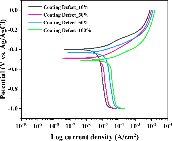
Potentiodynamic polarization curves of coated steel as a function of coating defects in 3.5 wt% NaCl solution

Electrochemical parameters obtained from the potentiodynamic polarization tests under different coating defect conditions in 3.5 wt% NaCl solution
To evaluate the severity of corrosion in the damaged areas, corrosion rates were calculated based on Faraday’s law using the following equation:
where a is the atomic weight, i is the corrosion current density, n is the number of electrons transferred per metal atom, and D is the density of the metal. As shown in Table 1, the corrosion rates of CD10%, CD30%, CD50%, and CD100% were 0.050, 0.078, 0.137, and 0.235 mm/yr, respectively. These values exceed the low corrosion rate threshold (0.025 mm/yr) recommended by NACE, indicating the necessity of implementing ICCP systems to mitigate corrosion.
3.2 Investigation on Cathodic Protection Potential and Impressed Current Density
According to the international standard ISO 12473: General Principles of Cathodic Protection in Seawater, the recommended cathodic protection potential range is -0.8 to -1.1 V vs. Ag/AgCl [10]. To minimize the required current density for cathodic protection (icp), the lowest cathodic potential that satisfies the NACE criterion for low corrosion rates (ENACE) was determined from polarization curves. Figure 2 presents the potentiodynamic polarization curve, anodic Tafel line, and icp for each cathodic potential. CD100% was presented as a representative. The ENACE was calculated to be -0 .58 V. additionally, 27.44, 36.15, and 43.36 μA/cm2 of current densities were required to maintain the potential of CD100% at -0.58, -0.7, and -0.8 V, respectively. The corresponding corrosion rates were reduced to 0.025, 6.65 × 10⁻¹⁰, and 3.16 × 10⁻¹¹ mm/yr, indicating that -0.58 and -0.7 V could also be considered effective cathodic protection potentials. Other calculated applied current densities and corrosion rates are summarized in Table 2.
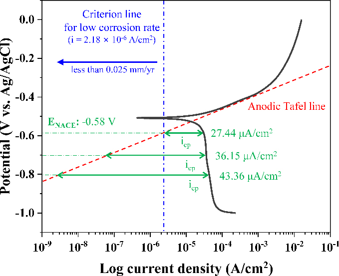
Calculated applied current density for cathodic protection (icp) and the anodic Tafel line of CD100% derived from the potentiodynamic polarization curve

Calculated applied current densities for cathodic protection and corrosion rates at the potentials as a function of coating defect levels
Potentiostatic tests were performed to replicate ICCP-applied environments and validate the calculated icp values, assessing the applicability to ICCP conditions. Figure 3 presents the recorded current densities of CD100% during the tests. Impressed current densities initially decreased sharply due to the formation of oxide films, which reduced the active surface area, as shown in the inset. However, as the oxide films continued to grow, their low electrical conductivity led to an increase in the required impressed current density. After around 20,000 s, the surface of CD100% stabilized, requiring 17.50, 29.62, and 34.30 μA/cm2 of icp at ENACE, -0.7, and -0.8 V, respectively.
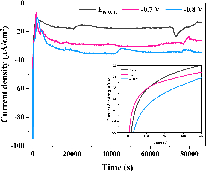
Records of applied current densities of CD100% during potentiostatic tests conducted at ENACE, -0.7 V, and -0.8 V in 3.5 wt% NaCl solution
To simulate icp on ICCP-applied ships under different cathodic potentials, which is challenging to measure in full-scale experiments, COMSOL Multiphysics was employed. Figure 4(a) presents a 3D simulation of the current density distribution at a cathodic protection potential of -0.8 V, while Figure 4(b), (c), and (d) illustrate the required icp values across the hull under cathodic potentials of ENACE, -0.7, and -0.8 V, respectively. In the ship modeling, the position and number of anodes were not optimized, resulting in a high current density near the 8 m region where the anodes are located. Hence, the current density values obtained from the simulation were selected from a spatial coordinate where the potential was stably maintained to establish the cathodic potential. The acquired impressed current densities at ENACE, -0.7, and -0.8 V were 27.84, 33.68, and 39.76 μA/cm2, respectively.
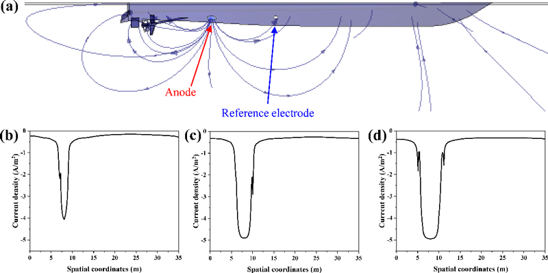
(a) Computational model of the current density distribution on a ship with CD100% hull and the corresponding icp values across the hull at cathodic potentials of (b) ENACE, (c) -0.7 V, and (d) -0.8 V
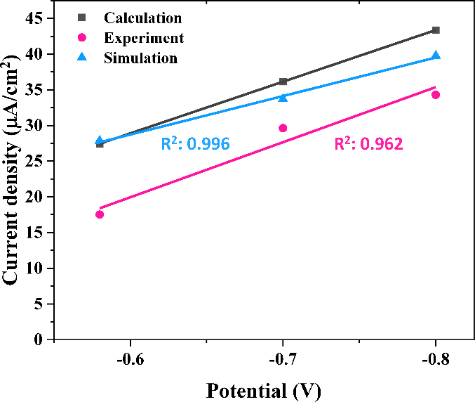
The calculated, measured, and simulated icp at ENACE, -0.7, and -0.8 V were summarized in Table 3 and the trend lines and coefficient of determination (R2) are presented in Figure 5. The R2 was calculated based on the square of the Pearson correlation coefficient. When the trend line was plotted based on the calculated values, the simulation and experimental results exhibited high R2 of 0.996 and 0.962, respectively. The experimentally obtained current density was lower than the calculated and simulated values, likely due to the lengthy duration of the potentiostatic tests. As observed in the potentiostatic tests, a higher current density was initially required before stabilizing over time, suggesting that prolonged exposure led to surface changes affecting current demand. Nevertheless, the results exhibited a strong correlation, indicating that cathodic protection potentials and required current densities can be reliably estimated through calculations and simulations.

Calculated, experimental, and simulated applied current densities for cathodic protection of CD100% as a function of cathodic protection potentials
3.3 Verification of Cathodic Potentials
To investigate the surface characteristics and evaluate the effectiveness of the applied cathodic potentials, EIS tests were conducted. The Nyquist plots of CD100% at Ecorr, ENACE, -0.7, and -0.8 V are presented in Figure 6(a). A depressed capacitive loop, which is commonly associated with charge transfer during the corrosion process, was observed at all cathodic potentials [11][12]. The semicircle diameter, representing charge transfer resistance (Rct), increased as the cathodic potential became more negative, enabling a comparative assessment of corrosion resistance. In contrast, an inductive loop at low frequency was only observed at Ecorr, ENACE. The presence of this inductive loop indicates that the adsorption of intermediate species, such as metal hydroxides, oxygen species, or H+ads, is actively occurring. This suggests that insufficient cathodic protection at Ecorr and ENACE has led to the accumulation of corrosion products on the surface of CD100% [13]. Conversely, at -0.7 and -0.8 V, where no inductive loop was observed, the system appears to be under effective cathodic protection, minimizing surface adsorption effects and stabilizing the electrode-electrolyte interface.
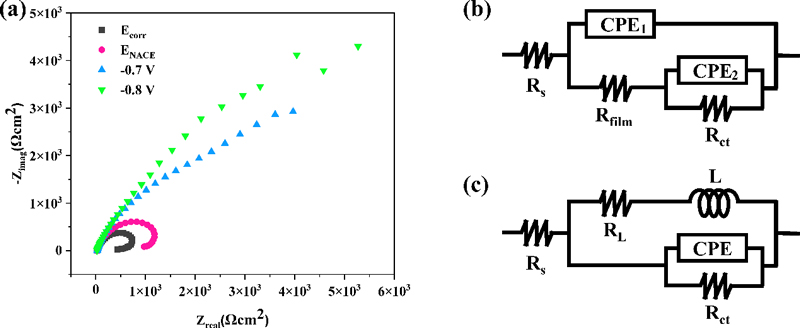
(a) Nyquist plots of CD100% at cathodic protection potentials of Ecorr, ENACE, -0.7 V, and -0.8 V and equivalent circuits of CD100% at (b) Ecorr and ENACE and (c) -0.7 V and -0.8 V
As the distinct characteristics depending on the cathodic potentials were exhibited, different equivalent electrical circuit (EEC) models were used. The impedance parameters of CD100% at Ecorr and ENACE were identified using the EEC shown in Fig. 6 (b). The circuit consists of the following components: Rs represents the solution resistance; RL and L correspond to the inductive elements; Rct denotes the charge transfer resistance; and Cdl (CPE) signifies the double layer capacitance. To achieve a more accurate fit, a constant phase element (CPE) was introduced instead of an ideal capacitor [12]. The impedance parameters of CD100% at -0.7 and -0.8 V, which demonstrated sufficient cathodic protection, were determined using the electrical equivalent circuit model shown in Figure 6(c). The circuit consists of the following components: Rs represents the solution resistance; Rfilm and Cfilm (CPE1) denotes the electrical resistance and capacitance of the oxide film, respectively; Rct is the charge transfer resistance; Cdl (CPE2) is the double layer capacitance.
The CPE impedance is expressed as:
Where Y0 is the magnitude of the CPE and n is the deviation from ideal capacitive behavior due to the surface roughness, porosity, or electrode heterogeneity [14].
The conversion of the CPE to capacitance was performed using the equation below [15]:
Where ωmax = 2πfmax, fmax is the frequency where the imaginary part of the impedance reaches its maximum.
The impedance parameters of CD100% at Ecorr and ENACE, -0.7 and -0.8 V are listed in Table 4. It can be noted that Rct increased as the cathodic protection potential became more negative. This aligns with the ICCP principle, where a more negative potential enhances the suppression of anodic dissolution by shifting the surface further into the cathodic region. As a result, Rct, which represents the difficulty of electron transfer in corrosion reactions, increases due to the reduced corrosion activity and the stabilization of the passive film on the metal surface. The Rfilm at -0.7 V was larger than that at -0.8 V, indicating that the suppression of anodic reactions at more negative potentials reduced oxide film formation, thereby decreasing Rfilm.

Impedance parameters of CD100% at cathodic protection potentials of Ecorr, ENACE, -0.7 V, and -0.8 V
The capacitance related to oxide film (Cfilm) and electrical double layer (Cdl) can be represented by:
Where ε is the dielectric constant, ε0 is the vacuum permittivity, A is the surface area of the electrode, and d is the thickness.
At cathodic protection potentials of -0.7 and -0.8 V, Cfilm showed nearly identical values, suggesting that the oxide film thickness was similar. This indicates that -0.7 V provides corrosion protection performance comparable to that of -0.8 V. Cdl at Ecorr and ENACE were lower than those at -0.7 and -0.8 V, which can be attributed to the increased corrosion reactions generating intermediate species. These species likely contributed to a thicker double layer, reducing the overall capacitance. On the other hand, the Cdl at -0.7 V was higher than that at -0.8 V. At more negative cathodic potentials, the cathodic reaction (O2 + 2H2O + 4e- → 4OH-) becomes more dominant, leading to a greater concentration of ions at the electrode surface. As a result, the electrical double layer thickens, causing a reduction in Cdl.
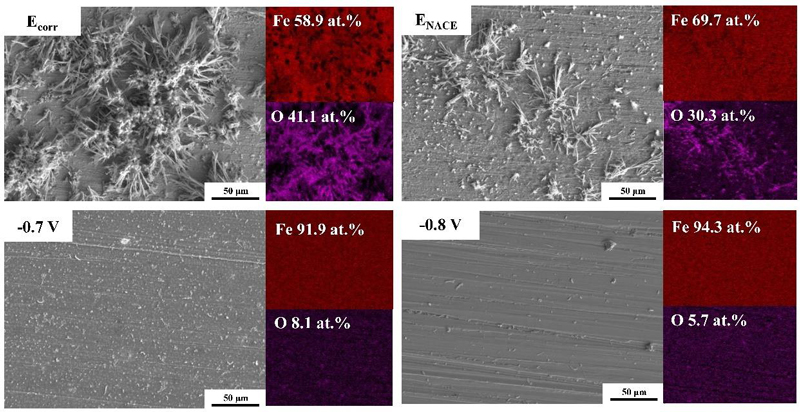
To further evaluate the effectiveness of cathodic potentials, SEM/EDS analysis was performed on the surface of CD100% after the potentiostatic tests. As depicted in Figure 7, the surfaces of CD100% at -0.7 and -0.8 V remained clear, whereas corrosion products were observed on CD100% at Ecorr and ENACE. Additionally, EDS mapping revealed that the Fe content in CD100% was 58.9, 69.7, 91.9, and 94.3 at%, while the O content was 41.1, 30.3, 8.1, and 5.7 at% at Ecorr, ENACE, -0.7, and -0.8 V, respectively. The lower Fe content and higher O content observed at Ecorr and ENACE indicate extensive oxide film formation, suggesting significant corrosion. Therefore, -0.7 V and -0.8 V can be considered effective cathodic protection potentials. These findings are consistent with the calculated corrosion rates and EIS results, further confirming the effectiveness of the cathodic potentials.
4. Conclusion
The efficient cathodic protection potentials and impressed current densities in ICCP systems for ships with coating defects were investigated through electrochemical analyses, computer simulations, and material characterization. The main findings are summarized as follows:
- 1. The corrosion rates of CD10%, CD30%, CD50%, and CD100% were 0.027, 0.050, 0.078, 0.137, and 0.235 mm/yr, respectively, exceeding the low corrosion rate threshold (0.025 mm/yr) recommended by NACE. This highlights the necessity of implementing ICCP systems to mitigate corrosion.
- 2. Cathodic protection potentials satisfying the low corrosion rate criterion proposed by NACE was estimated from the potentiodynamic polarization curves and the required current densities for the potentials were determined through calculations, simulations, and experiments. When the trend line was plotted based on the calculated values, the simulation and experimental results demonstrated strong correlations, with high R2 of 0.996 and 0.962, respectively.
- 3. Rct increased as the cathodic protection potential became more negative. In addition, no inductive loop was observed in the Nyquist plots at -0.7 and -0.8 V, whereas an inductive loop, indicative of active accumulation of corrosion products, appeared at Ecorr and ENACE. Furthermore, the oxide films generated at -0.7 and -0.8 V were significantly less pronounced than those at Ecorr and ENACE. These results suggest that -0.7 V also provides sufficient cathodic protection performance.
Acknowledgments
This research was supported by the Defense Acquisition Program Administration (DAPA) under the Defense Industry Component Localization Program (No. C220050).
Author Contributions
Conceptualization, U. Kim and S. Lee; Methodology, U. Kim; Software, U. Kim; Validation, U. Kim and S. Lee; Formal Analysis, U. Kim; Investigation, U. Kim, N. Kim; Resources, J. Sin, Y. Maeng, and S. Lee; Data Curation, U. Kim, N. Kim; Writing—Original Draft Preparation, U. Kim, N. Kim; Writing—Review & Editing, S. Lee; Visualization, U. Kim; Supervision, S. Lee; Project Administration, S. Lee; Funding Acquisition, J. Sin, Y. Maeng, and S. Lee.
References
-
S. Yan, G. -L. Song, Z. Li, H. Wanh, D. Zheng, F. Cao, M. Horynova, M. S. Dargusch, and L. Zhou, “A state-of-the-art review on passivation and biofouling of Ti and its alloys in marine environments,” Journal of Materials Science & Technology, vol. 34, pp. 421-435, 2018.
[https://doi.org/10.1016/j.jmst.2017.11.021]

- NACE International, Control of External Corrosion on Underground or Submerged Metallic Piping Systems, NACE International, 2013.
- D. N. Veritas, Cathodic Protection Design, Recommended Practice DNV-RP-B401, 2010.
- NACE International, Preparation, Installation, Analysis, and Interpretation of Corrosion Coupons in Oilfield Operations, NACE International, 2005.
-
C. Thiel, C. Broecheler, F. Ludwar, A. Rennings, J. Doose, and D. Erni, “A simple superposition formulation to predict the underwater electric potential signature of naval vessels,” Journal of Marine Science and Engineering, vol. 8, pp. 105-116, 2020.
[https://doi.org/10.3390/jmse8020105]

-
C. Thiel, K. Neumann, F. Ludwar, A. Rennings, J. Doose, and D. Erni, “Coating damage localization of naval vessels using artificial neural networks,” Ocean Engineering, vol. 192, pp. 106560-106566, 2019.
[https://doi.org/10.1016/j.oceaneng.2019.106560]

-
J. Wu, S. Xing, and F. Yun, “The influence of coating damage on the ICCP cathodic protection effect,” WIT Transactions on Engineering Sciences, vol. 65, pp. 89-96, 2009.
[https://doi.org/10.2495/ECOR090091]

-
E. Santana-Diaz and R. Adey, “Predicting the coating condition on ships using ICCP system data,” International Journal for Numerical Methods in Engineering, vol. 62, pp. 727-746, 2005.
[https://doi.org/10.1002/nme.1185]

- Corrosion Protection of a Ship Hull. Available: https://www.comsol.com/model/corrosion-protection-of-a-ship-hull-14565, .
- ISO 12473:2017 General principles of cathodic protection in seawater. Available: https://www.iso.org/standard/67729.html, .
-
K. Lima, V. M. Palva, D. Perrone, B. Ripper, G. Simões, M. L. M. Rocco, A. G. Veiga, and E. D’Elia, “Glycine max meal extracts as corrosion inhibitor mild steel in sulphuric acid solution,” Journal of Materials Research and Technology, vol. 9, pp. 12756-12772, 2020.
[https://doi.org/10.1016/j.jmrt.2020.09.019]

-
V. V. Torres, V. A. Rayol, M. Magalhães, G. M. Viana, L. C. S. Aguiar, S. P. Machado, H. Orofino, and E. D’Elia, “Study of thioureas derivatives synthesized from a green route as corrosion inhibitors for mild steel in HCl solution,” Corrosion Science, vol. 79, pp. 108-118, 2014.
[https://doi.org/10.1016/j.corsci.2013.10.032]

- H. H. Hernández, A. N. R. Reynoso, H. C. T. González, C. O. G. Morán, J. G. M. Hernández, A. M. Ruiz, J. M. Hernández, and R. O. Cruz, “Electrochemical impedance spectroscopy (EIS): A review study of basic aspects of the corrosion mechanism applied to steels,” Electrochemical Impedance Spectroscopy, pp. 137-144, 2020.
-
M. Sluyters-Rehbach, “Impedances of electrochemical systems: Terminology, nomenclature and representation-Part I: Cells with metal electrodes and liquid solutions,” Pure and Applied Chemistry, vol. 66, pp. 1831-1891, 1994.
[https://doi.org/10.1351/pac199466091831]

-
L. S. Rodrigues, A. F. Valle, and E. D’Elia, “Biomass of microalgae spirulina maxima as a corrosion inhibitor for 1020 carbon steel in acidic solution,” International Journal of Electrochemical Science, vol. 13, pp. 6169-6189, 2018.
[https://doi.org/10.20964/2018.07.11]


