Numerical study of exhaust gas flow characteristics in diesel particulate filters using CFD ANSYS Fluent
Copyright © The Korean Society of Marine Engineering
This is an Open Access article distributed under the terms of the Creative Commons Attribution Non-Commercial License (http://creativecommons.org/licenses/by-nc/3.0), which permits unrestricted non-commercial use, distribution, and reproduction in any medium, provided the original work is properly cited.
Abstract
Design modifications alone in marine diesel engines are not sufficient to meet the stringent emission regulations. Therefore, incorporation of exhaust aftertreatment systems such as diesel particulate filters has proven to be essential in reducing exhaust gas emissions. This study investigated the changes in exhaust gas flow characteristics including inlet velocity, inlet temperature, porosity of the filter, and the filter location in the diesel particulate filter affect the back pressure using computational fluid dynamics. Results showed a minimum and maximum back pressure of 31.44 mbar and 49.71 mbar respectively. The back pressure decreased by 3.21% with the increase in inlet temperature from 350°C to 431°C and by 0.07% as the porosity of the filters was increased from 60% to 70%, and by 0.04% from 70% to 80%. However, the back pressure increased by 52.92% when the inlet velocity was increased from 7.4 m/s to 10.3 m/s. Based on the filter location, velocity vector distributions showed that the closer filter to the exhaust gas inlet had a high velocity concentrated at the center, which is non-uniform. The results provide insights to enhance the stability, performance, and reliability of diesel particulate filters in marine diesel engines.
Keywords:
Back pressure, Computational fluid dynamics, Diesel particulate filter, Porosity1. Introduction
The marine industry has seen massive growth in recent years due to the increased worldwide trade and expansion of other maritime activities [1]. Therefore, the two main concerns related to this expansion are the protection of the maritime environment and improvement of the safety of marine transportation. The International Maritime Organization has introduced strict emission regulations regarding the exhaust gas pollutants from ships as part of its efforts to protect the marine environment.
Increasingly strict regulations for both coastal and international ships have posed a stringent challenge for designers, manufacturers, and operators of marine engines. Recently, many countries are promoting the utilization of alternative fuels such as liquefied natural gas and liquefied petroleum gas in marine diesel engines. However, commercial vessels such as cargo ships and container ships, as well as coastal shipping such as fishing vessels, ferries, and tugboats, still rely heavily on diesel-fueled engines.
The dominance of marine diesel engines is due to several advantages, such as high fuel efficiency, strong durability, and consistent reliability from the stable performance characteristics [2]-[5]. However, exhaust gas of marine diesel engines contains a lot of pollutants such as nitrogen oxides, carbon monoxide, hydrocarbons, and particulate matter (PM). PM, which is majorly composed of mineral ash fractions, nitrates and sulphates, unburned hydrocarbons, and soot particles, is a major pollutant. PM has caused serious environmental and health hazards, including cancer, heart diseases, and respiratory disorders [6]. Therefore, most research in marine diesel engines is focused on reducing PM emissions.
Today, marine diesel engines have reached the most advanced level of modification technologies in terms of design. Design modifications, including fuel injection system optimization and improved combustion efficiency, have significantly reduced exhaust gas emissions. However, to meet the progressively stringent environmental regulations, modification technologies alone are not sufficient to reduce PM emissions. Therefore, the use of aftertreatment systems such as diesel particulate filters (DPFs), exhaust gas recirculation, and selective catalytic reduction has proven to be essential. Previous research works have acknowledged DPF as the most successful aftertreatment technology [7]-[10].
DPFs have superior filtration efficiency, however their operational efficiency thoroughly depends on DPF design. To correctly design a DPF, understanding the exhaust gas flow characteristics is crucial. Exhaust gas flow characteristics such as back pressure, velocity changes, and flow uniformity have a strong influence on filtration efficiency, regeneration frequency, and the durability of the DPF. Moreover, the flow characteristics have a significant influence on the engine’s fuel efficiency and the overall engine’s performance.
Therefore, this numerical study aims to analyze how the changes in exhaust gas flow characteristics, specifically inlet temperature, inlet velocity, porosity of the filter, and the location of the filter in the DPF design, affect the back pressure on the DPF. The study modeled 12 simulation cases using the computational fluid dynamics (CFD) software ANSYS Fluent 2019R2. Afterward, the results were analyzed using the CFD Post software. The results of this study are crucial to optimizing the DPF design, which is further essential in enhancing the stability, performance, and reliability of aftertreatment systems in marine engines.
2. Numerical Analysis
The use of the CFD approach in analyzing research problems related to DPFs porous media has been increasing and has proven very crucial [11]-[14]. This is due to the complex of experimental studies and theoretical calculations of analysis of backflow in DPFs. Moreover, the CFD approach saves time, reduces costs that accompany experimental investigations, and offers near real-time unparalleled insights.
2.1 Geometric Modeling
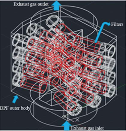
In this numerical study, AUTOCAD 2024 software was used to create a three-dimensional (3D) geometric model of the DPF structure. The structure was composed of exhaust gas inlet and outlet, 24 filters, and a housing structure. Afterward, the 3D model was exported in a compatible format to the ANSYS Fluent 2019R2 software. Figure 1 presents the 3D geometric design of the DPF structure. Whereas, Table 1 lists the principal specifications of the DPF device.
2.2 3D Computational Mesh
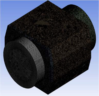
In the ANSYS Fluent software, the DPF computational mesh was created. Mesh generation is a crucial process in the simulation analysis as it contributes to the reliability and accuracy of simulation results. The global meshing technique with an element size of 0.01 m was used to generate the computational mesh. Moreover, the entire computational mesh domain used the unstructured and fully tetrahedron mesh because it can discretize complex geometries quickly with little user intervention [15]. Figure 2 presents the 3D computational mesh of the DPF structure.
In addition, the quality of the mesh of the computational domain is critical for the suitability of the mesh during the simulation for the optimization of simulation results and convergence rate. Table 2 presents the computational mesh properties and statistics.
2.3 Simulation Models
To accurately model the behavior of exhaust gas flow through the porous filters in the DPF structure, several simulation models in ANSYS Fluent software were utilized. Generally, the flow behavior of exhaust gases involves changes in both temperature and pressure. In addition, the flow of exhaust gases in the inlet and outlet parts is turbulent. In contrast, flow within the filters is laminar, which is defined by inertial and viscous loss coefficients along the inlet symmetrical axis [16]. To account for the turbulence effects, the realizable K-epsilon (k-ε) with a near-wall treatment of the standard wall functions model was enabled. The realizable k-ε model is economical and reliable with great accuracy across a broad range of turbulent flows [16][17].
To account for the changes in pressure in the flow behavior, the pressure-based option in the solver was selected. The pressure approach in the solver is derived from the continuity and momentum equations. Moreover, the energy model was utilized since there is a presence of heat exchange between the exhaust gases flowing in through the DPF material structure.
The species transport model was activated to precisely simulate the detailed chemical reactions of the gaseous species within the filters. DPFs not only enhance particulate matter trapping but also allow species reactions and conversion, and regeneration processes. The species used in the simulation were nitrogen, oxygen, carbon dioxide, and water vapor.
For accurately designing the filter properties in the simulation, the porous medium was used. The porous medium model is highly significant in solving several problems related to filters, flow distributors, heat exchangers, tube banks, packed bed reactors, and perforated plates [16][17]. This is because the porous medium is highly suitable for the inertial resistance, viscous resistance, and porosity within the cell zones. Table 3 summarizes the CFD models used during the simulation process.
2.4 Simulation Boundary Conditions
The boundary conditions of the simulation were adjusted to the engine’s operating conditions. The DPF structure was incorporated on a V-12, four-stroke cycle, Caterpillar 3512B diesel engine with a rated speed of 1800 rpm and utilizes the turbocharged aftercooled aspiration system. Table 4 presents the engine performance data that the DPF is incorporated into. Generally, marine engines are optimized to run at 50% and 75% load for efficiency and durability. Therefore, in this particular simulation analysis, 50% and 75% engine load data were utilized. At an engine load of 50% and 75%, the exhaust gas inlet velocity was 7.4 m/s and 10.3 m/s respectively. Consequently, the exhaust gas inlet temperatures used in this case study as were 350°C and 431°C for the respective 50% and 75% loads of the experimental engine performance. The gas outlet pressure that is the gauge pressure was set to 0 Pascals to simplify the boundary conditions which is relative to the atmospheric pressure.
In addition, the porosity of the cell zone conditions of the filters used in marine diesel engines varies depending on the material used and design. A low porosity filter is attributed to high filtration efficiency with increased back pressure and vice versa. Therefore, in this analysis, porosity was varied from 60% to 80 % in 10% increment and other factors attributed to porous medium modeling such as inertial resistance and viscous resistance were maintained constant throughout the simulation cases.
2.5 Simulation Solution Setup
In this simulation, the pressure was set to second order, momentum to second order upwind, whereas turbulent dissipation rate and turbulent kinetic energy were set to first order upwind. Moreover, the pressure-velocity coupling scheme was set to a coupled algorithm, gradient to least squares cell-based, and pseudo transient was enabled. To account for convergence, an absolute convergence of 0.001 for velocity, k, continuity, and epsilon was utilized.
Afterward, the solution initialization was solved using the standard initialization method from the exhaust gas inlet to the outlet. The simulation was run for 1000 iterations on a 128 GB installed RAM, Windows workstation with an Intel (R) Xeon (R) W-3323 CPU @ 3.50 GHz, 64-bit operating system, and x64-based processor. There were a total of 12 simulation cases based on the simulation boundary conditions, and each case was solved within a maximum of 5 hours. After the calculation process, the results were analyzed.
3. Simulation Results
The results of this study were based on the analysis of the effects of exhaust gas inlet temperature and velocity, and changes in porosity of the filter cell zone conditions on the back pressure. The back pressure units were in millibars (mbar). Table 5 shows the simulation results of back pressure in mbar at porosity (a) 60%, (b) 70%, and (c) 80%. From the results, the minimum back pressure was 31.44 mbar, and the maximum back pressure was 49.71 mbar, which both of the back pressures are less than the class standard back pressure of 68 mbar according to the manufacturer’s specification.
4. Discussions
4.1 Back Pressure According to Exhaust Gas Inlet Temperature
Across all the porosities, as the exhaust gas inlet temperature is increased from 350°C to 431°C, the back pressure decreases slightly. Choe et al. [8] conducted a basis study on the optimal design of the integrated PM/NOx reduction device using CFD approach and the results showed similar trends of back pressure decreasing as the exhaust gas inlet temperature increases. Additionally, other research studies such Li et al. [18] who performed an experimental evaluation of DPF performance loaded over Pt and sulfur-resisting material for marine diesel engines explained similar trends and attribute it to the following explanations. Firstly, as the exhaust gas inlet temperatures increase, the oxidation of soot in the DPF increases, decreasing the exhaust gas flow resistance, and thereby reducing the back pressure across all the various porosities. Secondly, according to Combined Gas Law, which explains the relationship between pressure, volume, and the temperature of a fixed amount of gas. This relationship translates, in a DPF structure, which is a fixed volume, as the exhaust gas inlet temperature increases, the exhaust gases expand. Expansion of exhaust gases results in decreased gas density, which enhances reduced flow resistance, resulting in a decrease in back pressure.
4.2 Back Pressure According to Exhaust Gas Inlet Velocity
As the exhaust gas inlet velocity increases from 7.4 m/s to 10.3 m/s, the back pressure increases significantly by an average of 52.92% across all the simulation cases. Yamamoto et al. [19] conducted a numerical simulation of fluid dynamics in a monolithic column and the findings indicated that increased inlet velocity increases the back pressure. Moreover, in comparison to the variation of exhaust gas inlet temperature, exhaust gas inlet velocity has a significant change across all the porosities of the DPF structure. This shows that the effect of inlet velocity is higher than inlet temperature. The following explanations are based on the Darcy-Weisbach equation application across a porous medium. The equation relates the pressure drop in a flow analysis to factors such as flow velocity, medium characteristics, friction, and fluid density. The increase in exhaust gas inlet velocity increases flow resistances attributed to inertial and viscous effects, leading to a significant increase in back pressure [20]-[22].
4.3 Back Pressure According to the Porosity of the Filter
The porosity of a DPF is an important consideration that influences the regeneration cycle depending on the back pressure characteristics and filter performance. Back pressure across the DPF decreases slightly by 0.07% as the porosity of the filters was increased from 60% to 70%, and by 0.04% when the porosity was increased from 70% to 80% across all the simulation cases. Meng et al. [22] performed a numerical simulation of diesel particulate filter performance optimization through pore structure analysis and the results deduced that as the porosity of the porous medium increases the pressure drop decreases of the DPF. As the porosity of the filter in this study was increased from 60%, to 70%, and 80%, the permeability of the filter increases, which reduces the viscous and inertial effects. This reduces the back pressure in the DPF structure. Moreover, increased porosity means more void spaces in the filter material, hence reducing the resistance to exhaust gas flow and consequently reducing the back pressure [19][23].
4.4 Velocity Vector Distribution According to Filter Location
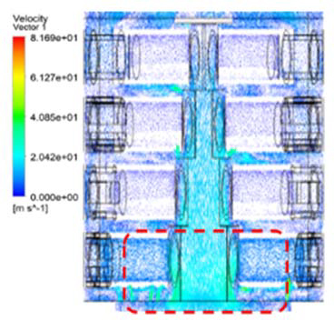
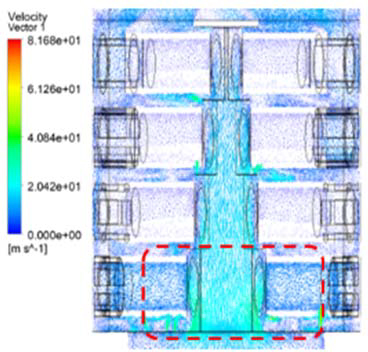
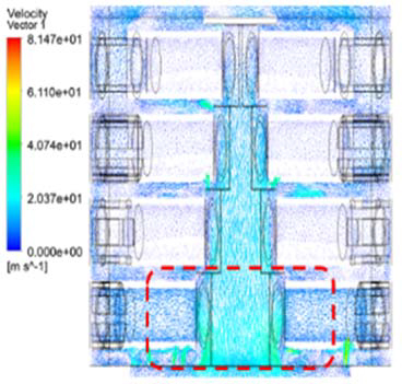
The location of the filters in the DPF affects flow uniformity which is crucial to the efficiency, performance, and durability of the structure. Choe et al. [8] on the basis study on the optimal design of the integrated PM/NOx reduction device using CFD approach highlighted the necessity to consider the arrangement location of the filters in the integrated PM/NOx reduction device as it affects the flow uniformity of exhaust gases. To study the effect of filter location, the velocity vector distribution along the ZX plane was used. Figure 6 presents velocity vector distribution across all the porosity cases (a) 60%, (b) 70%, and (c) 80% at the inlet velocity of 7.4 m/s, and the exhaust gas inlet temperature of 350°C. In all the simulation cases, the velocity vectors indicated that the filter closer to the exhaust gas inlet was concentrated with high velocities ranging between 20.37 m/s to 61.10 m/s at the center and decelerated to as it went into the filter. The velocity decreases to below 20.37 m/s as it approaches the exhaust gas outlet. Therefore, the velocity at the filter closer to the exhaust gas outlet which is mostly covered with deep blue color shade representing a lower velocity shows a good uniformity.
5. Conclusion
The numerical study analyzed how the changes in exhaust gas flow characteristics, specifically inlet temperature, inlet velocity, porosity of the filter, and the location of the filter in the DPF design, affect the back pressure on the DPF. The study modeled 12 simulation cases using ANSYS Fluent 2019R2. Afterward, the results were analyzed using the CFD Post software. The following are the main conclusions deduced from the study:
- 1) The numerical analysis back pressure conditions satisfied, the class standard back pressure of 68 mbar according to the manufacturer’s specification.
- 2) Among the 12 simulation cases, the minimum back pressure was 31.44 mbar at the exhaust gas inlet temperature 431°C, inlet velocity 7.4 m/s, and 80% porosity of the filter. Whereas maximum back pressure was 49.71 mbar at the exhaust gas inlet temperature 350°C, inlet velocity 10.3 m/s, and 80% porosity of the filter.
- 3) Increased exhaust gas inlet temperature from 350°C to 431°C, led to an average of 3.21% decrease in the engine back pressure in the DPF across all the simulation cases.
- 4) The engine back pressure of the DPF across all the simulation cases increased by an average of 52.92% when the exhaust gas inlet temperature was increased from 7.4 m/s to 10.3 m/s.
- 5) The engine back pressure in the DPF decreased by 0.07% as the porosity of the filters was increased from 60% to 70%, and by 0.04% when the porosity was increased from 70% to 80% across all the simulation cases.
- 6) Among all the exhaust gas flow characteristics simulated, exhaust inlet velocity has a greater influence on the back pressure in the DPF. Whereas the porosity of the filters has a least influence on the backpressure in the DPF.
- 7) The velocity vector distribution showed that the closer filter to the exhaust gas inlet had velocity ranging between 20.37 m/s to 61.10 m/s compared to the filter near the exhaust gas outlet whose velocity is below 20.37 m/s.
While the above-mentioned conclusions offer valuable insights into the effects of exhaust gas flow characteristics, it is noteworthy to acknowledge that these findings are based on a specific DPF design geometry. Therefore, the generalization of the findings to optimize other DPF designs creates a future research gap to explore alternative DPF design variations, exhaust gas flow conditions, and experimental validation analysis which is crucial to enhancing the stable performance and reliability of aftertreatment systems in a wider range of marine diesel engines.
Acknowledgments
This work was supported by the Technology Innovation Program (RS-2024-00459805, Development of fuel supply equipment for methanol fueled ship) funded by the Ministry of Trade, Industry & Energy (MOTIE, Korea).
Author Contributions
Conceptualization, Methodology, Software, Validation, Formal Analysis, Visualization, Writing-Original Draft Preparation, Writing-Review & Editing, N. I. Ahmed; Formal Analysis, Final review, J. K. Kim; Methodology, Software, Validation, S. J. Choe; Project Administration, J. H. Choi; Conceptualization, Supervision, Project Administration, Writing-Review & Editing, W. J. Lee.
References
-
P. Ni, X. Wang, and H. Li, “A review on regulations, current status, effects and reduction strategies of emissions for marine diesel engines,” Fuel, vol. 279, 118477, 2020.
[https://doi.org/10.1016/j.fuel.2020.118477]

-
C. O. Park, J. Yang, and J. Kwon, “Comparative assessment of the effects of higher alcohols/diesel blends on performance and emissions of a direct-injection diesel engine,” Journal of Advanced Marine Engineering and Technology, vol. 48, pp. 55-62, 2024.
[https://doi.org/10.5916/jamet.2024.48.2.55]

-
G. Bao, C. He, T. Zi, J. Li, and X. Liu, “Analysis of gas flow and PM movement characteristics inside diesel particulate filter channel,” Process Safety and Environmental Protection, vol. 186, pp. 1134-1148, 2024.
[https://doi.org/10.1016/j.psep.2024.04.054]

-
M. A. Kalam, H. H. Masjuki, H. M. Cho, M. H. Mosarof, M. I. Mahmud, M. A. Chowdhury, and N. W. Zulkifli, “Influences of thermal stability, and lubrication performance of biodegradable oil as an engine oil for improving the efficiency of heavy duty diesel engine,” Fuel, vol. 196, pp. 36-46, 2017.
[https://doi.org/10.1016/j.fuel.2017.01.071]

-
M. K. Kang, K. Y. Min, S. U. Park, and J. D. Choi, “An experimental study on the air pollutant emission characteristics of high-speed diesel engine for small coastal ships according to the application of the LP EGR and DOC-DPF systems,” Journal of Advanced Marine Engineering and Technology, vol. 46, pp. 1-8, 2022.
[https://doi.org/10.5916/jamet.2022.46.1.1]

-
M. A. Je, S. H. Jung, T. Y. Jeong, S. C. Hwang, and J.S. Moon, “Exhaust Gas Recirculation (EGR) effect on two-stroke diesel engines under sailing condition,” Journal of Advanced Marine Engineering and Technology, vol. 48, pp. 1-8, 2024.
[https://doi.org/10.5916/jamet.2024.48.1.1]

-
Y. Shi, Y. Zhou, Z. Li, Y. Cai, X. Li, Y. He, and J. Fang, “Effect of temperature control conditions on DPF regeneration by nonthermal plasma,” Chemosphere, vol. 302, 134787, 2022.
[https://doi.org/10.1016/j.chemosphere.2022.134787]

-
S. J. Choe, V. C. Pham, W. J. Lee, J. S. Kim, J. K. Kim, H. Park, I. G. Lim, and J. H. Choi, “A basis study on the optimal design of the integrated PM/NOx reduction device,” Journal of the Korean Society of Marine Environment & Safety, vol. 28, pp. 1092-1099, 2022.
[https://doi.org/10.7837/kosomes.2022.28.6.1092]

-
H. You, R. Gao, P. Hu, K. Liang, X. Zhou, X. Huang, and M. Pan, “Sensitivity analysis of diesel particulate filters to geometric parameters during soot loading and its multi-objective optimization,” Process Safety and Environmental Protection, vol. 159, pp. 251-265, 2022.
[https://doi.org/10.1016/j.psep.2021.12.040]

-
Z. Yang, Z. Tan, Q. Tan, and S. Tu, “Analysis of carbon particulate matter removal performance of dual-fuel marine engine with DOC+ CDPF,” Atmosphere, vol. 14, 1041, 2023.
[https://doi.org/10.3390/atmos14061041]

-
W. Xu, C. Kou, E. Jiaqiang, C. Feng, and Y. Tan, “Effect analysis on the flow uniformity and pressure drop characteristics of the rotary diesel particulate filter for heavy-duty truck,” Energy, vol. 288, 129820, 2024.
[https://doi.org/10.1016/j.energy.2023.129820]

-
J. Fu, Y. Tang, J. Li, Y. Ma, W. Chen, and H. Li, “Four kinds of the two-equation turbulence model's research on flow field simulation performance of DPF's porous media and swirl-type regeneration burner,” Applied Thermal Engineering, vol. 93, pp. 397-404, 2016.
[https://doi.org/10.1016/j.applthermaleng.2015.09.116]

-
T. Deuschle, U. Janoske, and M. Piesche, “A CFD-model describing filtration, regeneration and deposit rearrangement effects in gas filter systems,” Chemical Engineering Journal, vol. 135, pp. 49-55, 2008.
[https://doi.org/10.1016/j.cej.2007.03.019]

-
S. Bensaid, D. L. Marchisio, and D. Fino, “Numerical simulation of soot filtration and combustion within diesel particulate filters,” Chemical Engineering Science, vol. 65, pp. 357-363, 2010.
[https://doi.org/10.1016/j.ces.2009.06.051]

- ANSYS, Inc. ANSYS Fluent User’s Guide 2021 R2, 2021.
- ANSYS, Inc. ANSYS Fluent Tutorial Guide 17.0, 2016.
- ANSYS, Inc. ANSYS Fluent Theory Guide, 15.0, 2013.
-
X. Li, K. Li, H. Yang, Z. Wang, Y. Liu, T. Shen, S. Tu, and D. Lou, “Experimental evaluation of DPF performance loaded over Pt and sulfur-resisting material for marine diesel engines,” PLOS One, vol. 17, e0272441, 2022.
[https://doi.org/10.1371/journal.pone.0272441]

-
K. Yamamoto and Y. Tajima, “Numerical simulation of fluid dynamics in a monolithic column,” Separations, vol. 4, 3, 2017.
[https://doi.org/10.3390/separations4010003]

-
X. Wang, Y. Deng, and Y. Liu, “Two-dimensional numerical studies of particle motion and deposition in the channel of diesel particulate filters,” Royal Society Open Science, vol. 8, 211162, 2021.
[https://doi.org/10.1098/rsos.211162]

-
K. Yamamoto and T. Sakai, “Effect of pore structure on soot deposition in diesel particulate filter,” Computation, vol. 4, 46, 2016.
[https://doi.org/10.3390/computation4040046]

-
Z. Meng, J. Zhang, Z. Bao, W. Wang, H. Deng, and Y. Hu, “Numerical simulation of diesel particulate filter performance optimization through pore structure analysis,” Process Safety and Environmental Protection, vol. 177, pp. 1072-1084, 2023.
[https://doi.org/10.1016/j.psep.2023.07.041]

-
K. Yamamoto and Y. Toda, “Numerical simulation on flow dynamics and pressure variation in porous ceramic filter,” Computation, vol. 6, 52, 2018.
[https://doi.org/10.3390/computation6040052]


