Dynamic manipulation of a large object using a leader–assistant mobile robot system
Copyright © The Korean Society of Marine Engineering
This is an Open Access article distributed under the terms of the Creative Commons Attribution Non-Commercial License (http://creativecommons.org/licenses/by-nc/3.0), which permits unrestricted non-commercial use, distribution, and reproduction in any medium, provided the original work is properly cited.
Abstract
This study addresses the transportation of large objects using a leader–assistant robot system. The transport strategy involves three phases: first, the robots couple with the object; second, they move to the goal position; and third, the robots decouple from the object. In previous studies, we examined the coupling and decoupling configurations of the first and third phases and presented a kinematic control method for the second phase. In this study, we considered the dynamics of a leader–assistant system and investigated a dynamic path-tracking control method. To this end, we initially formulated a dynamic equation in terms of the position and orientation of the object (control target) without the interaction force terms between the object and n number of robots, which allows us to handle the leader–assistant system like a single robot for object manipulation. Subsequently, a straight-line path tracking control method using a dynamic equation was presented. Through simulations, it was verified that the dynamic path-tracking control method is effective for leader–assistant systems.
Keywords:
Object transportation, Multiple robots, Leader–assistant system, Dynamic model, Dynamic control1. Introduction
The development of the transportation and robotics industries gives rise to an urgent need for automatic transport methods to replace manual handling. Related studies [1]-[8] have demonstrated that cooperative object transportation using multiple mobile robots is efficient.
Burghardt et al. [1] proposed two wheeled mobile robots physically connected to an object to transport large cargo. Inglett and Rodríguez-Seda [2] used a pair of mobile robots to push and manipulate objects. However, these methods can only handle specific shapes and limited quantities of objects, rendering transport inefficient.
To address these disadvantages, Huang and Zhang [3] introduced a method that uses a ball–string–ball structure to link robots to encircle an object. Hunte and Yi [4] proposed a method that uses multiple mobile robots with a pallet structure to transport an object. These methods can transport more than one object simultaneously; however, collisions between objects can occur, and precise control of the object’s position and orientation is difficult.
Wada et al. [5][6] proposed multiple mobile robots with actuators coupled to the bottom of an object. This method achieves the omnidirectional movement of an object and precise control of its position and orientation.
Caging strategies and formation robots have been proposed to handle large and heavy loads. Alkilabi et al. [7] achieved object control with multiple robots through a caging strategy, and Rangsichamras et al. [8] proposed a method with a leader–follower formation system to transport objects linked to robots with actuators.
This study deals with object transportation using a leader–assistant system in which the leader guides the object to track a given path, whereas the assistants are the remaining robots that provide the force to move the target object. Unlike related studies, this system does not require an additional actuator for coupling the robots and object.
The transport strategy is divided into three phases. First, the robots couple with the object, subsequently move to a goal position by tracking a given path, and finally decouple from the object, as shown in Figure 1. Previously, we examined the coupling and decoupling configurations of an object and robots in the first and third phases, in which the robots could couple/decouple with/from an object without any actuators [9]. Following this, we presented a kinematic control method for the second phase that transports an object along given paths [10].
In this study, we focused on the dynamics of a leader–assistant system and investigated a dynamic path-tracking control method. For this purpose, we first formulated a dynamic equation expressed in terms of the position and orientation of the object (control target). Considering the velocity constraints at the coupling points, we can eliminate the interaction force terms between the object and robots from the dynamic equation. The resultant dynamic equation allows us to handle a leader–assistant system like a single robot for the manipulation of the object. Subsequently, a straight-line path tracking control method using a dynamic equation was presented.
Additionally, the leader can be switched to an assistant in certain situations. For example, if the object needs to be moved in the backward direction, that is, on the opposite side of the leader, leader switching is preferable because not all robots need to turn around for backward movement. We present an example of this through a simulation.
The remainder of this paper is organized as follows. Section 2 formulates the dynamic equation of the leader–assistant system, and Section 3 presents the path-tracking control method using the dynamic equation. Section 4 presents the simulations performed and their results.
2. Dynamic Model of the Leader–Assistant System
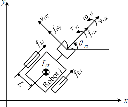
In this section, we first present the dynamic equations of the robot and object, and then formulate the combined dynamic equation of the leader–assistant system. Let mri be the mass of the i-th robot, ωri be the angular velocity of the i-th robot, Izr be the moment of inertia of the z-axis of the i-th robot, vri= (vrixvriy)T∈R2 and ωri be the linear and angular velocities of the i-th robot, respectively, and fri= (frixfriy)T∈R2 and τri be the forces and moment exerted by the i-th robot, respectively. The dynamic equation of the i-th robot can be expressed as follows:
| (1) |
where is the inertia matrix, is the Coriolis matrix, , and . From Figure 2, Fri can be obtained as follows:
| (2) |
where fRi and fLi are the linear forces generated by the right and left wheels, respectively.
Similarly, considering an object moved by the robots, the dynamic equation for the object can be expressed as follows:
| (3) |
where is the inertia matrix, is the Coriolis matrix, , is the linear velocities, ωo is the angular velocity, is the forces and moment generated by the robots, , mo is the mass, and Izo is the moment of inertia of z-axis.
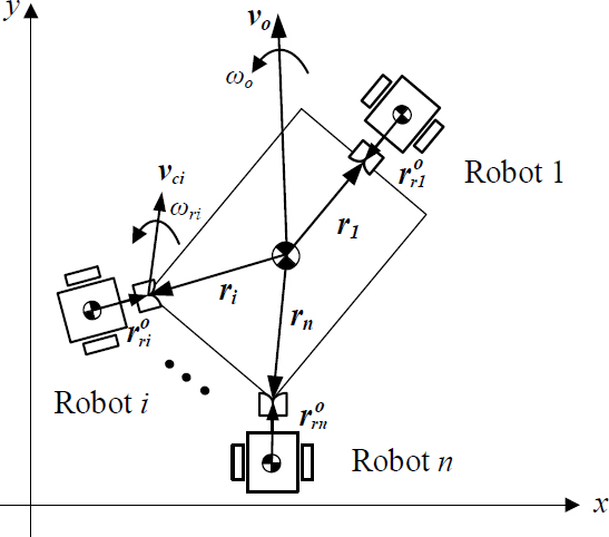
To combine the two dynamic equations formulated above, we considered the interaction forces between the object and robot. Let ri∈R2 be the position vector from the object’s center of mass to the coupling point, be the position vector from the i-th robot’s center of mass to the coupling point, and fci∈R2 be the force exerted at the coupling point. All position vectors are expressed with respect to the body frame attached to the object. As shown in Figure 3, considering n number of robots and an object, the force and moment relationships between the robots and object are given by
| (4) |
| (5) |
| (6) |
| (7) |
From Equations (4)-(7), Equations (1) and (3) can be rewritten as follows:
| (8) |
| (9) |
where
E is the orthogonal rotation matrix rotating an arbitrary vector counterclockwise by an angle of 90° in a plane and is given as
| (10) |
and
| (11) |
where , θri and θo are the heading angles of the i-th robot and the object, respectively, and is the rotation matrix rotating by an angle of . Equation (8) can be generalized for n robots, as follows:
| (12) |
where
,
,
,
,
,
.
Combining Equations (9) and (12), we have
| (13) |
where
,
,
,
,
,
and O3×3n is a 3×3n zero matrix.
Here, we consider the velocity constraints at the coupling points to eliminate the coupling force fc in Equation (13). As shown in Figure 4, because the velocities at the coupling points vci, produced by the robots and the object, are the same, we obtain
| (14) |
which can be rewritten as
| (15) |
The control target is the position and orientation of the object, that is, Vo. We can select Vo as an independent variable as follows:
| (16) |
| (17) |
where I3 is a 3×3 identity matrix, is the pseudo-inverse of , and . Differentiating Equation (16) with respect to time yields:
| (18) |
Multiplying NT to both sides of Equation (13) and considering Equations (15), (16), and (18), the dynamic equation of the independent variable Vo can be obtained as
| (19) |
where and . Note that this dynamic equation does not have a coupling force term and allows us to handle a leader–assistant system like a single robot.
3. Path-Tracking Control
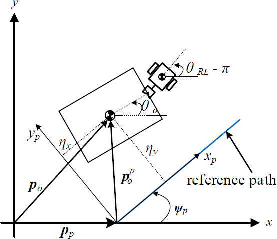
The objective of the path-tracking control is to make the heading angle error of the leader and the position error of the object zero. From Figure 5, the position error of the object can be obtained as
| (20) |
where pO and pp are the position vectors pointing the object and the origin of the xp–yp frame (path frame) from the origin of the x–y frame, respectively, is the position vector of the object with respect to the path frame, ψp is the angle between the xp-axis and the x-axis, and R(ψp)∈R2×2 is a rotation matrix. The orientation error of the leader against the path angle ψp can also be yielded as
| (21) |
Our control purpose is to ensure that the position error ηy and orientation error ηψ approach zero. To achieve this, the desired velocities and heading rate of the leader can be given by
| (22) |
where vRL and ωRL are the desired linear and angular velocities of the leader, respectively, vrd is the desired speed of the leader, θRL is the heading angle of the leader, and k1 and k2 are the control gains. These values are expressed with respect to the x–y frame.
Let VOd∈R3 be the desired velocity of the object generated by the leader, and rL∈R2 and rRL∈R2 be the position vectors pointing to the relevant coupling point from the center of mass of the object and the center of mass of the leader, respectively. The desired linear and angular velocities of the object can then be obtained as
| (23) |
where (I2 ErL)# is the pseudo-inverse of (I2 ErL), and and are VRL and rRL expressed with respect to the body frame at the object.
Consequently, from Equation (19), the forces and moments Fr that should be exerted by the robots for path-tracking control are given by
| (24) |
where , ★, and K = diag(ku, kv, kr) is the control gain matrix.
4. Simulation
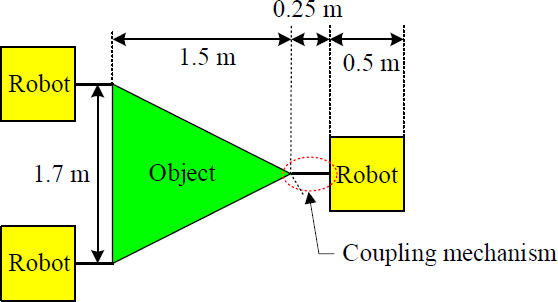
Table 1 lists the mass and moment of inertia of the robot and object used in the simulations, and Figure 6 shows the sizes of the object and robot. For the simulations, the control gains were set to k1=1, k2=1.9, and ku= kv= kr=1000, and the desired moving speed of the leader is vrd=0.5 m/s. Two simulations were performed. One was for tracking a given path consisting of three straight lines to verify the proposed path-tracking control method, and the other was for showcasing the switching of the leader to one of the assistants for better object transportation.
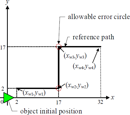
Figure 7 shows the planned path for the simulation used to verify the path-tracking control. The object was initially located at the origin of the x–y frame and tracked three straight lines consisting of waypoints {(xw1, yw1), (xw2, yw2)}, {(xw2, yw2), (xw3, yw3)}, and {(xw3, yw3), (xw4, yw4)}. If the object falls within the allowable error circle, the leader begins tracking the next straight line. The allowable error circle is given by:
| (25) |
where po=(xo, yo)T is the position of the object and re is the radius of the allowable error circle.
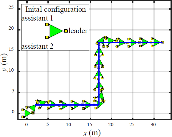
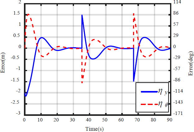
Figure 8 shows the simulation results for tracking the path shown in Figure 7. The initial posture of the object is (0, 0) m and θo= 0o, that of the leader is (1.5, 0) m and θRL= 180o, that of assistant 1 is (-1, 0.85) m and θr1= 0o, that of assistant 2 is at (-1, -0.85) m and θr2= 0o, and the radius of allowable error circle is re=1.5 m. The results show that the robots appropriately moved the object along the given straight-line paths. Figure 9 shows the position and heading errors during the simulation. The position error ηy and the heading angle error ηψ approach zero. Through this simulation, we verified the effectiveness of the proposed path-tracking control method for leader–assistant systems.
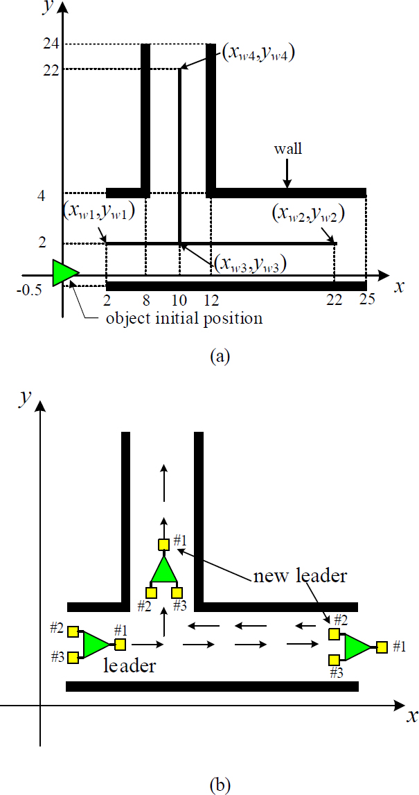
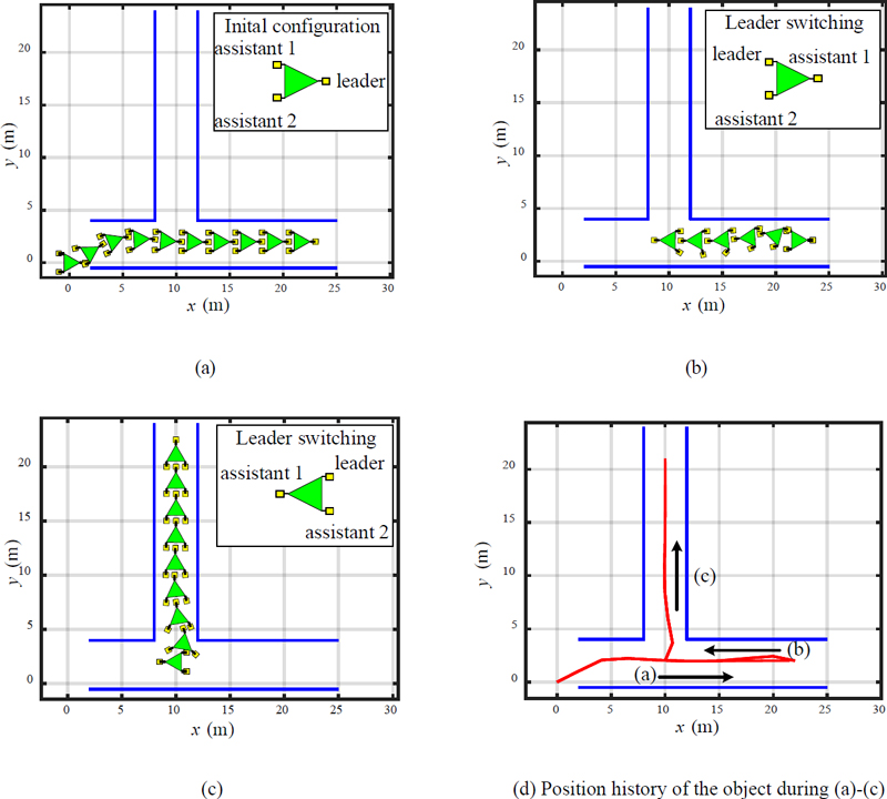
Figure 10 shows the planned path used to demonstrate leader switching. The control sequence is as follows: the object is initially located at the origin of the x–y frame; first, the object is transported along the straight-line path comprising waypoints {(xw1, yw1), (xw2, yw2)}; second, the leader is switched to one of the assistants, and the object is transported along the straight-line path consisting of {(xw2, yw2), (xw3, yw3)}; finally, the leader is switched to one of the assistants, and the object is transported along the straight-line path consisting of {(xw3, yw3), (xw4, yw4)}.
Figure 11 shows the simulation results. The initial posture of the object is (0, 0) m and θo = 0o, that of the leader is (1.5, 0) m and θRL= 180o, that of assistant 1 is (-1, 0.85) m and θr1= 0o, that of assistant 2 is (-1, -0.85) m and θr2 = 0o, and the allowable error circle is set to be re = 0.1 m to allow passage through the vertical narrow corridor (the path consisting of {(xw3, yw3), (xw4, yw4)}). The path-tracking control performances are provided separately for each straight-line path, as shown in Figures 11(a)–(c), where Figure 11(d) shows the position history of the object for all paths.
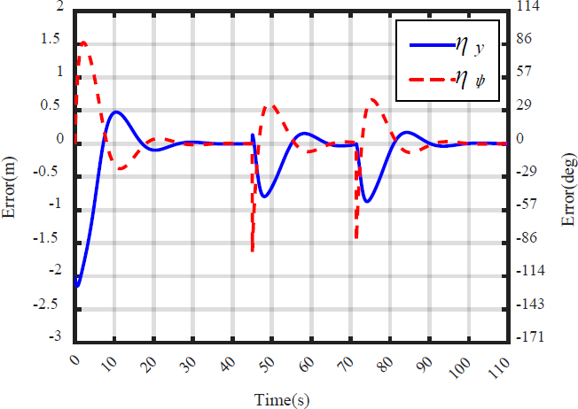
Leader switching occurs at the waypoints (xw2, yw2) and (xw3, yw3). If the object arrives at (xw2, yw2), assistant 1 becomes the leader for backward motion. Subsequently, assistant 1 is switched to the leader at (xw3, yw3) to move to (xw4, yw4). From the simulation results, we can confirm that the proposed path-tracking control is effective even in the case of switching the leader to one of the assistants. In addition, leader switching can prevent the unnecessary rotation of all robots and be useful for complicated paths. In addition, we can observe that the position error ηy and the heading angle error ηψ approach zero in Figure 12. In this simulation, we selected the next leader intuitively just to show the possibility of leader switching. The development of a detailed selection rule will be included in our future work.
5. Conclusion
This study discusses the collaborative transport of large objects using a leader–assistant system. We formulated a dynamic equation for a leader–assistant system and proposed a straight-line path-tracking control method using the dynamic equation. Simulations verified that the proposed path-tracking control method is effective and that leader switching is useful for complicated paths. Our future work will involve the development of a detailed leader-switching rule and an experimental study.
Author Contributions
Conceptualization, J. -K. Choi; Methodology, J. -K. Choi, H. Tian and H. -H. Kim; Software, H. Tian and J. -K. Choi; Formal Analysis, H. Tian, J. -K. Choi and H. -H. Kim; Investigation, H. Tian and J. -K. Choi; Resources, H. Tian and J. -K. Choi; Data Curation H. Tian and J. -K. Choi; Writing-Original Draft Preparation, H. Tian and J. -K. Choi; Writing-Review & Editing, J. -K. Choi, H. Tian and H. -H. Kim; Visualization, H. Tian and J. -K. Choi; Supervision, J. -K. Choi.
References
-
A. Burghardt, P. Gierlak, and W.Skwarek, “Modeling of dynamics of cooperating wheeled mobile robots,” Journal of Theoretical And Applied Mechanics, pp. 649-659, 2021.
[https://doi.org/10.15632/jtam-pl/141668]

-
J. E. Inglett and E. J. Rodríguez-Seda, “Object transportation by cooperative robots,” Proceedings of IEEE Southeast Conference 2017, pp. 1-6, 2017.
[https://doi.org/10.1109/SECON.2017.7925348]

-
Y. Huang and S. Zhang, “Cooperative object transport by two robots connected with a ball-string-ball structure,” IEEE Robotics and Automation Letters, vol. 9, no. 5, pp. 4313-4320, 2024.
[https://doi.org/10.1109/LRA.2024.3379802]

-
K. Hunte and J. Yi, “Pose control of a spherical object held by deformable sheet with multiple robots,” IFAC-PapersOnLine, vol. 55, no. 37, pp. 414-419, 2022.
[https://doi.org/10.1016/j.ifacol.2022.11.218]

-
K. Miyashita and M. Wada, “An omnidirectional cooperative transportation of a large object by differential drive wheeled mobile robots with the active-caster control,” Proceedings of IEEE/SICE International Symposium on System Integration (SII), pp. 932-937, 2022.
[https://doi.org/10.1109/SII52469.2022.9708808]

-
Y. Arai and M. Wada, “Study on omnidirectional cooperative transport system using multiple dual-wheeled mobile robots with active-caster control,” Proceedings of IEEE/ASME International Conference on Advanced Intelligent Mechatronics (AIM), pp. 690-695, 2023.
[https://doi.org/10.1109/AIM46323.2023.10196226]

-
M. H. M. Alkilabi, A. Narayan, and E. Tuci, “Cooperative object transport with a swarm of e-puck robots: Robustness and scalability of evolved collective strategies,” Swarm Intelligence, vol. 11, pp. 186-207, 2017.
[https://doi.org/10.1007/s11721-017-0135-8]

-
P. Rangsichamras, N. Wittayaarereekul, S. Tantinarasak, I. Khuankrue, and C. Janya-Anurak, “Cooperation of autonomous mobile robots with different maneuverability in transportation,” Proceedings of 62nd Annual Conference of the Society of Instrument and Control Engineers (SICE), pp. 187-192, 2023.
[https://doi.org/10.23919/SICE59929.2023.10354235]

-
J. -K. Choi, H. Tian, and Y. -S. Ha, “Object transportation using multiple mobile robots: coupling and decoupling configuration of an object and robots,” Journal of Advanced Marine Engineering and Technology, vol. 47, No. 6, pp. 360-366, 2023.
[https://doi.org/10.5916/jamet.2023.47.6.360]

-
H. Tian, J. -K. Choi, and H. -H. Kim. “Kinematic manipulation of a large object using a leader–assistant mobile robot system,” Journal of Advanced Marine Engineering and Technology, vol. 48, no. 5, pp. 331-337, 2024.
[https://doi.org/10.5916/jamet.2024.48.5.331]


