Effects of wave generation distance in particle-based numerical wave tank on the analysis of overtopping wave energy converters
Copyright © The Korean Society of Marine Engineering
This is an Open Access article distributed under the terms of the Creative Commons Attribution Non-Commercial License (http://creativecommons.org/licenses/by-nc/3.0), which permits unrestricted non-commercial use, distribution, and reproduction in any medium, provided the original work is properly cited.
Abstract
The accuracy of performance assessments for overtopping wave energy converter (OWEC) is significantly influenced by reflected waves. This study evaluates the impact of reflected waves on OWEC performance using environmental data from the coastal region of Ulleungdo. A two-dimensional numerical simulation, based on the Smoothed Particle Hydrodynamics (SPH) method, was conducted to analyze how design variables affect overtopping performance and energy efficiency. Recognizing the overestimation issues in previous research due to the absence of reflected wave considerations, this study integrates updated environmental conditions to mitigate such impacts. The findings indicate that changes to the upper and lower structures in the models resulted in overall energy efficiency variations of approximately 1%, indicating minimal differences. However, significant changes in energy efficiency were observed across individual reservoir levels. Specifically, the energy efficiency of Reservoirs 3 and 4 decreased, while the efficiency of Reservoir 2 increased by an equivalent amount, with the magnitude of variation ranging from 6% to 8%. This study highlights the importance of addressing reflected wave effects in OWEC design, emphasizing the need for three-dimensional simulations and experimental validations in future research.
Keywords:
Overtopping Wave Energy Converter, Energy efficiency, Smoothed-Particle Hydrodynamics, 2D numerical simulation, Reflected wave1. Introduction
Growing concerns about environmental issues and the transition from fossil fuels to renewable energy sources have increased the interest in various forms of sustainable energy production, including solar, wind, geothermal, and ocean energy. South Korea, with its geographical proximity to the ocean, has significant potential for marine energy development, estimated at 18,000 MW, including tidal (6,500 MW), wave (1,000 MW), and ocean thermal (4,000 MW) energy. Despite this potential, marine energy contributes only 0.6% of the nation's energy mix, necessitating further exploration and development.
Wave energy converters (WECs) are typically categorized into three types: oscillating body systems that convert wave kinetic energy directly into electricity, oscillating water column systems that utilize airflows generated by wave-induced oscillations to drive turbines, and overtopping systems that transform over-topped wave energy into potential energy for electricity generation. Among these, OWECs are particularly sensitive to wave overtopping flow rates, which directly influence power generation. Consequently, ongoing research has focused on optimizing design parameters and configurations to maximize efficiency.
Various researchers have investigated the influence of design parameters on wave energy converters. Kofoed [1] conducted model experiments to examine how design variables impact the performance of wave energy converters. Victor et al. [2] evaluated the effects of different design scenarios on overtopping efficiency and power output. Jungrungruengtaworn et al. [3] compared overtopping performance based on model experiments and numerical simulations, specifically analyzing the design parameters of inlets for multi-stage overtopping converters. Jungrungruengtaworn and Hyun [4] analyzed the overtopping performance of multi-stage overtopping wave energy converters based on various inlet design parameters. Mustapa et al. [5] validated the proposed wave energy converter design through three-dimensional analysis results. De Barros et al. [6] studied the effects of attaching additional sub-structures to wave energy converters and their subsequent performance changes. In previous studies, analyses were conducted by either excluding the substructure or adjusting the distance from the wave generator to reduce the influence of reflected waves. However, for accurate analysis, it is essential to include the substructure and perform an analysis on the distance between the wave generator and the substructure, considering the effects of reflected waves.
In previous studies, the design of wave energy converters was typically based on design parameters, with their shapes verified through energy efficiency assessments. Prior to this research, an analysis of wave characteristics along the South Korean coastline was conducted to select a target region (Kim et al., [7]). Following the selection of the target region, the energy efficiency and structural stability of the wave energy converter's substructure were evaluated (An et al., [8]). However, earlier studies did not adequately account for the effects of reflected waves during the energy efficiency simulation process, leading to overestimated efficiency values. To address this issue, the present study incorporates the influence of reflected waves by revising the environmental conditions. Based on these updated conditions, the performance of the wave energy converter was analyzed, and the optimal design was determined.
2. Analysis Methodology
Fluid dynamics analysis methods are typically divided into Eulerian approaches, which examine fluid flow within a fixed spatial domain, and Lagrangian approaches, which describe the fluid as particles with physical properties such as mass, density, pressure, and velocity. OWEC experiences significant discontinuous changes at the free surface of the fluid. In such cases, the Eulerian approach often suffers from numerical diffusion at the discontinuous free surface, leading to reduced accuracy in analysis. In contrast, the Lagrangian approach, which calculates the motion of individual particles, demonstrates strengths in handling discontinuous free surface calculations. The SPH method is a Lagrangian-based numerical technique for fluid analysis. It computes the physical properties of particles through their interactions with neighboring particles, which are estimated using a kernel function. This relationship is represented by Equation (1), and the SPH method approximates this equation in its discretized form, shown in Equation (2):
| (1) |
| (2) |
In these equations,F(ri) denotes the physical property at particle ri, while rj represents neighboring particles. mj and ρj are the mass and density of particle j, respectively. The kernel function W(ri-rj,h) describes the interaction between particles i and j and is dependent on the smoothing length h. The kernel function is expressed as follows:
| (3) |
Here,r represents the distance between particle i and its neighboring particle j, while q=r/h represents the dimensionless distance between particles. The coefficient αD is defined as 10/7πh2 for two-dimensional cases and 1/πh3 for three-dimensional cases.
2.2 Momentum and State Equations
The SPH method models fluid motion using the Navier-Stokes equations. The equation of motion with respect to time is given by:
| (4) |
Here, represents the pressure gradient, v0∇2v is the viscous stress term, and g denotes the gravitational acceleration. To model viscosity, artificial viscosity is introduced, and this study utilizes the formulation proposed by Monaghan [9], expressed as:
| (5) |
In Equation (5), P and ρ represent the pressure and density at points i and j, respectively. The viscosity term ∏ij is defined as follows:
| (6) |
Here, rij=ri-rj and vij=vi-vj represent the position and velocity differences between particles i and j. The average speed of sound is given as , and α is set to 0.01. The term μij in Equation (6) is defined as:
| (7) |
where, η2=0.01h^2
To simulate incompressible fluids, the SPH method assumes slight compressibility, represented by the following equation of state from Monaghan et al. [10]:
| (8) |
In Equation (8), γ=7, , and ρ0=1000kg/m3 represents the reference density. c0 denotes the speed of sound at the reference density.
3. OWEC Design Parameters
3.1 Model Conditions
The target study area was selected as Ulleungdo, the same region analyzed in the previous research by An et al. [8]. While the earlier study employed a scale of 1/10 of the actual sea conditions, this paper adopts a scale of 1/20 to align with the dimensions used in future model experiments. The corresponding values are presented in Table 1.
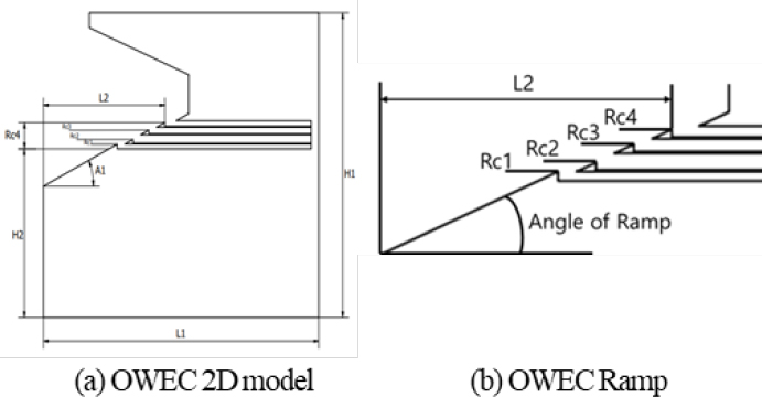
The reference model employed in this study was consistent with the design proposed by An et al. [8]. The blueprint and dimensions of the baseline model are depicted in Figure 1 and outlined in Table 2.
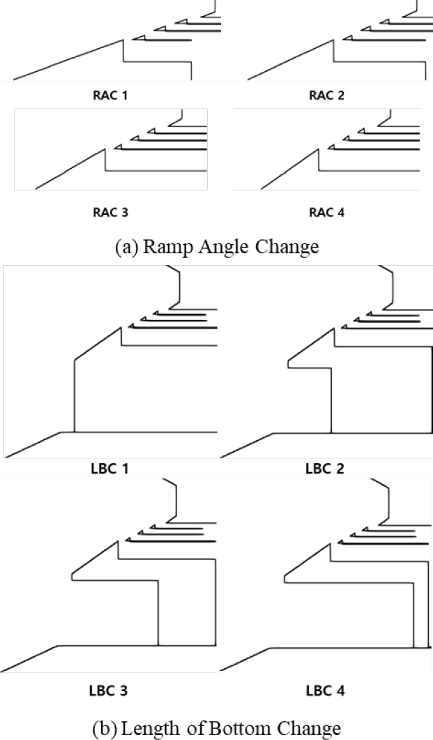
Similar to the prior research, design variables for the wave energy converter's upper and lower structures were selected. The ramp angle was adjusted as a key variable, ranging from 20 to 35 degrees in increments of 5 degrees. Additionally, the length of the lower structure was reduced by 6 meters for each configuration. The detailed shapes and specifications of the modified models are presented in Figure 2 and Table 3.
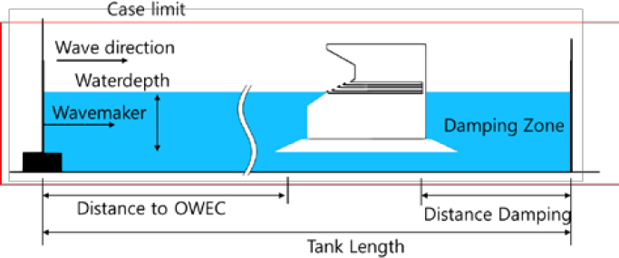
In this study, a two-dimensional numerical wave tank was developed to evaluate the performance of the OWEC. The setup and numerical parameters of the wave tank are presented in Figure 3 and detailed in Table 4. To minimize the impact of reflected waves, a key issue in previous research, the distance between the wave generator and the structure was set to 8.5 meters, equivalent to 3.54 times the wavelength.
4. Results
4.1 Performance Analysis of OWEC
The efficiency of an OWEC is assessed by comparing its over-topping flow rate and energy conversion performance. This study utilizes hydraulic efficiency, a parameter proposed by Margheritini et al. [11], to quantify the energy efficiency associated with overtopping waves. The hydraulic efficiency is defined by the following equation:
| (9) |
Where, Pcrest represents the potential energy of the overtopped water. For multi-stage OWEC, this is calculated as the total sum of the potential energy contributions from all reservoirs:
| (10) |
In the above equation, ρ is the fluid density, g is the gravitational acceleration, qj is the overtopping flow rate into the j-th reservoir, and Rc,j is the elevation of the j-th reservoir inlet above the sea level. Flow rates were averaged over one wave period for accuracy. The energy of the incoming wave, Pwave is expressed as:
| (11) |
Here, H is the height of the incident wave, c is its phase velocity, d is the water depth, and k is the wave number. This formulation provides a basis for evaluating the relationship between the incident wave energy and the energy captured by the OWEC.
4.2 Analysis of Results and Discussion
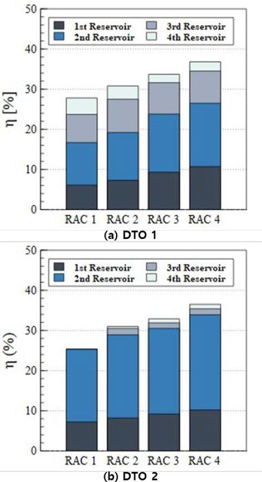
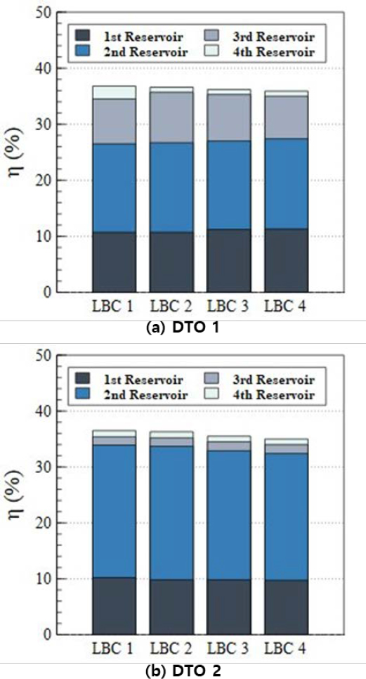
This study aims to address the limitations of previous research by analyzing the effects of reflected waves on OWEC performance. The results for models with varying ramp angles (RAC) are presented in Table 5 and Figure 4, while those for models with modified substructure lengths (LBC) are shown in Table 6 and Figure 5. In this study, the results of the previous study by An et al. [8] are referred to as DTO 1 (Distance to OWEC 1) while the results of this study are designated as DTO 2.
The analysis of models with varying ramp angles revealed overall hydraulic efficiency differences ranging from 0.2% to 2.5%, as shown in Table 5 and Figure 4. While the total hydraulic efficiency showed minimal variation, Figure 4 highlights significant differences in the hydraulic efficiency of individual reservoirs. In the DTO 1, where the distance between the wave generator and the structure was shorter, efficiency was distributed across all reservoirs. In contrast, DTO 2, the majority of the hydraulic efficiency was concentrated in the first and second reservoirs.
In the case of RAC 1, the efficiency of the 1st reservoir showed an increase within a 1% range. The efficiency of the 2nd reservoir increased by approximately 7% in DTO 2 compared to DTO 1, while the 3rd reservoir experienced a 7% decrease. Similarly, the efficiency of the 4th reservoir showed a reduction of 4%. While there are variations in the efficiency changes across different reservoirs, the efficiency of the 3rd and 4th reservoirs decreased, whereas the 2nd reservoir exhibited an improvement. This discrepancy is attributed to the excessive overtopping caused by reflected waves in DTO 1, leading to fluid inflow into higher reservoirs. This effect was observed across all models, with greater impacts seen in designs with lower ramp angles. However, in DTO 2, the influence of reflected waves was reduced, preventing excessive overtopping and leading to an increase in the flow rate entering the 2nd reservoir. This trend was consistently observed across all RAC 1 to 4 models.
For models with modified substructure lengths, the overall hydraulic efficiency decreased as the length of the substructure was reduced. This trend is evident in Table 6 and Figure 5(b), where the majority of the energy efficiency DTO 2 was concentrated in the first and second reservoirs. However, DTO 1, the second and third reservoirs exhibited higher efficiency compared to DTO 2.
This behavior is attributed to the influence of reflected waves overlapping with incident waves. In DTO 1, excessive overtopping occurred, leading to fluid ingress into higher levels, whereas in DTO 2, the reduced effect of reflected waves mitigated over-topping. In DTO 1, the overtopped flow directed toward Reservoir 3 was redirected to Reservoir 2 in DTO 2. As presented in Table 6, for LBC Model 1, the efficiency of Reservoir 2 demonstrated a 7.9% difference between DTO 1 and DTO 2. Similarly, Reservoirs 3 and 4 exhibited differences of 6.5% and 1.2%, respectively. The reductions in efficiency for Reservoirs 3 and 4 were compensated by an increase in Reservoir 2. This trend was consistently observed across the model, resulting in efficiency variations ranging from 6% to 8%. These differences are linked to the excessive overtopping caused by reflected waves. The analysis of RAC and LBC models confirms that the distance between the wave generator and the structure significantly influences the performance of OWECs due to the effects of reflected waves.
5. Conclusion
This study incorporated the effects of reflected waves, which were not sufficiently considered in previous research, to analyze changes in energy efficiency resulting from variations in the geometry of OWEC. Using particle-based simulation software and wave data from the Ulleungdo region, the models from prior studies (Figure 2) were reevaluated to assess the overtopping performance of the structures.
In the previous study, the distance between the wave generator and the OWEC was set at 0.94 times the wavelength, which significantly amplified the influence of reflected waves. To address this, the present study increased this distance to 3.54 times the wavelength, minimizing the impact of reflected waves. The results were then compared to the findings from the previous study. As the ramp angle increased, the hydraulic efficiency of the 1st and 2nd reservoirs showed an upward trend, while that of the 3rd and 4th reservoirs decreased. These findings suggest that steeper angles favor wave energy contribution during the descending motion rather than the ascending motion. Notably, models with ramp angles of 30 degrees or greater exhibited most of their hydraulic efficiency in the 1st and 2nd reservoirs.
The analysis of models with varying ramp angles (RAC) revealed that the overall hydraulic efficiency in DTO 2 was lower compared to DTO 1, with differences ranging from 0.2% to 2.4%. Smaller ramp angles showed greater deviations in efficiency. Furthermore, this study highlighted significant differences in the contribution of individual reservoirs to the total efficiency. Unlike DTO 1, where reflected waves caused excessive overtopping and higher contributions from the 2nd and 3rd reservoirs, DTO 2 demonstrated that efficiency was primarily concentrated in the 1st and 2nd reservoirs, as the effects of reflected waves were mitigated.
For models with varying substructure lengths (LBC), the overall efficiency also decreased in DTO 2 compared to DTO 1, with reductions ranging from 0.3% to 0.9%. This suggests that substructure length has less sensitivity to reflected waves compared to ramp angle variations. However, significant differences were observed in the efficiency of individual reservoirs. For example, in the LBC 1 model, the efficiency differences between DTO 2 and DTO 1 for the 1st, 2nd, 3rd, and 4th reservoirs were 0.5%, 7.9%, 6.5%, and 1.2%, respectively. Similar to the RAC models, excessive overtopping caused by reflected waves in DTO 1 led to higher contributions from the 2nd and 3rd reservoirs.
The findings of this study underscore the importance of accurately accounting for reflected waves when designing OWEC. The insights gained can provide valuable guidance for the precise design and optimization of OWEC. However, it is important to note that the current analysis was conducted using two-dimensional simulations. Future studies should incorporate three-dimensional modeling and physical experiments to validate these findings. Additionally, the regular wave conditions used in this study differ from real-world irregular wave conditions, which should be considered in subsequent research.
Acknowledgments
This work was supported by National R&D Program through the National Research Foundation of Korea (NRF) funded by the Korea government (Ministry of Science and ICT) (No. 2021R1I1A3057230).
Author Contributions
Conceptualization, S.-H. An and J.-H. Lee; Methodology, S.-H. An; Software, S.-H. An; Validation, S.-H. An and J.-H. Lee; Formal Analysis, S.-H. An; Investigation, S.-H. An; Resources, S.-H. An; Data Curation, S.-H. An; Writing—Original Draft Preparation, S.-H. An; Writing—Review & Editing, J.-H. Lee; Visualization, S.-H. An; Supervision, J.-H. Lee; Project Administration, J.-H. Lee; Funding Acquisition, J.-H. Lee.
References
- J. P. Kofoed, Wave Overtopping of Marine Structures Utilization of Wave Energy, Ph. D. Dissertation, Aalborg University, Aalborg, Denmark, 2002.
-
L. Victor, P. Troch, and J. P. Kofoed, “On the effects of geometry control on the performance of overtopping wave energy converters,” Energies, vol. 4, no. 10, pp. 1574-1600, 2011.
[https://doi.org/10.3390/en4101574]

- S. Jungrungruengtaworn, R. Reabroy, N. Thaweewat, and B. S. Hyun, “Numerical and experimental study on hydrodynamic performance of multi-level OWEC,” Ocean Systems Engineering, vol. 10, no.4, pp. 359-371, 2020.
-
S. Jungrungruengtaworn and B. S. Hyun, “Effects of struc-ture geometry on energy harvesting efficiency of multi-stage overtopping wave energy converters,” Journal of the Korean Society for Marine Environment & Energy, vol. 20, no. 3, pp. 136-144, 2017.
[https://doi.org/10.7846/JKOSMEE.2017.20.3.136]

-
M. A. Mustapa, O. B. Yaakob, and Y. M. Ahmed, “Nu-merical simulation of the overtopping-ramp design of a multi-stage overtopping wave energy breakwater hybrid device,” International Journal of Innovative Technology and Exploring Engineering, vol. 9, no. 1, pp. 4902-4911, 2019.
[https://doi.org/10.35940/ijitee.A8113.119119]

-
S. A. Da Silva, J. C. Martins, E. D. dos Santos, L. A. O. Rocha, B. N. Machado, L. A. Isoldi, and M. das Neves Gomes, “Constructal design applied to an overtopping wave energy converter locate on paraná coast in brazil,” Sustainable Marine Structures, vol. 6, no. 2, pp. 1-14, 2024.
[https://doi.org/10.36956/sms.v5i2.1113]

-
G. G. Kim, S.H. An, and J.H. Lee, “Review of the optimal locations of coastal sea area for operating wave energy converter in Korea,” Journal of Advanced Marine Engineering and Technology, vol. 46, no. 4, pp. 172-181, 2022.
[https://doi.org/10.5916/jamet.2022.46.4.172]

-
S. H. An, J. H. Lee, G. G. Kim, and D. H. Kang, “Optimal design of overtopping wave energy converter substructure based on smoothed particle hydrodynamics and structural analysis,” Journal of the Korean Society of Marine Environment & Safety, vol. 29, no. 7, pp. 992-1001, 2023.
[https://doi.org/10.7837/kosomes.2023.29.7.992]

-
J. J. Monaghan, “Smoothed particle hydrodynamics,” Annual Review of Astronomy and Astrophysics, vol. 30, pp. 543-574. 1992.
[https://doi.org/10.1146/annurev.astro.30.1.543]

-
J. J. Monaghan, R. A. Cas, A. M. Kos, and M. Hallworth, “Gravity currents descending a ramp in a stratified tank,” Journal of Fluid Mechanics, vol. 379, pp. 39-69, 1999.
[https://doi.org/10.1017/S0022112098003280]

-
L. Margheritini, D. Vicinanza, and P. Frigaard, “SSG wave energy converter: Design, reliability and hydraulic performance of an innovative overtopping device,” Renewable Energy, vol. 34, no. 5, pp. 1371-1380, 2009.
[https://doi.org/10.1016/j.renene.2008.09.009]


