Electromagnetic compatibility of open control cabinets by arbitrary wireless devices inside nuclear power plants: parallel polarization
Copyright © The Korean Society of Marine Engineering
This is an Open Access article distributed under the terms of the Creative Commons Attribution Non-Commercial License (http://creativecommons.org/licenses/by-nc/3.0), which permits unrestricted non-commercial use, distribution, and reproduction in any medium, provided the original work is properly cited.
Abstract
This paper presents the electromagnetic scattering characteristics of an open nuclear power plant (NPP) cabinet at application frequencies of 2.4 and 5 GHz when the incident wave is parallelly polarized. The electromagnetic field strengths were investigated at each frequency and the corresponding shielding effectivenesses (SEs) were obtained. The SEs at 2.4 GHz were higher than those at 5 GHz; however, the differences were not significant. SEs calculated with a dielectric or magnetic wall introduced on the cabinet door were slightly improved compared to those without a dielectric or magnetic wall. The SE was also investigated with respect to the spacing between adjacent digital modules. The electric SE improved when the spacing from the suggested structure was increased by 20 mm. The findings are expected to be beneficial for designing NPP cabinets.
Keywords:
Electromagnetic compatibility, Electromagnetic interference, Electromagnetic field strength, Nuclear power plant, Shielding effectiveness1. Introduction
Wireless communication systems are widely used not only for personal purposes but also for social and national usage and various application fields. Their application in power plants is no exception. Electromagnetic fields of various frequencies are widespread indoors; however, power plant managers do not always recognize this. Arbitrarily generated electromagnetic waves are widespread in nuclear power plants (NPPs) and can affect other electronic equipment. NPPs have instrumentation and control (I&C) equipment that control power generation, called digital modules (DMs), which are located in a large cabinet. Electromagnetic waves from wireless devices impact the I&C equipment inside the cabinet, causing possible damage or malfunction of the equipment. Therefore, it is necessary to strictly examine electromagnetic interference (EMI) and regulate electromagnetic levels.
One of the best methods to check the effect of electromagnetic waves entering the cabinet is to investigate the shielding effectiveness (SE). SE is a measure of the attenuation or reduction of the electric or magnetic field at a specific point in the space occupied by a shield between the measurement point and the source. It is necessary to examine the influence of electromagnetic waves by applying an SE at a point between the DMs inside the cabinet of an NPP. Furthermore, it is important to develop a method for reducing the influence of electromagnetic waves.
Abundant research has been conducted on the application of wireless devices in NPPs. A previous study examined the electromagnetic scattering characteristics inside an NPP cabinet containing DMs and confirmed their properties based on changes in the radio frequency and permeability when ferrite sheets were inserted across the cabinet door [1]. In addition, the DMs inside the cabinet were assumed to be lumps, and the scattering characteristics in space were confirmed when the incident electric fields were polarized perpendicularly and parallelly [2][3]. By extending these studies, another study investigated the scattered field properties for cases where the DMs were divided into several sections and the back door was partially open [4]. In addition, electromagnetic scattering fields were generated when parasitic line current was generated randomly inside the cabinet [5]. Moreover, when wireless devices were located inside a room in an NPP, the area where electromagnetic waves formed strongly was analyzed, and an exclusion zone for the I&C equipment was proposed [6][7]. Furthermore, the electromagnetic compatibility of electromagnetic waves generated by an open cable box was systematically analyzed [8]. In the present study, the electromagnetic scattering characteristics and SEs were rigorously investigated with several DMs inside the cabinet arranged at regular intervals and the incident electric field polarized in parallel. In addition, SEs have been investigated with dielectric or magnetic materials placed on doors and with wider spacings between adjacent DMs. These results can be compared with the scattering properties and SEs for perpendicularly polarized incident fields and cases in which a ferrite sheet is added to the opening space [1].
2. Interior Geometry of the Cabinet and its Analysis
Several studies have been conducted on the application of wireless devices in NPPs. In a previous study, the electromagnetic scattering characteristics inside an NPP cabinet containing DMs were examined and confirmed based on the changes in the radio frequency and permeability when ferrite sheets were inserted across the cabinet door [1]. These scattering properties and SEs were investigated by applying a perpendicularly polarized incident field and ferrite sheet to the opening space. However, in this study, we analyzed the results obtained with a parallelly polarized incident field considered for the same structure. These results are comparable to those of the previous study [1].
The structure of the cabinet analyzed in this study is shown in Figure 1 and is the same as that described previously [1]. A few DMs with regular intervals have been described more elaborately than other structures that assume several DMs as a group [2][3]. However, in the present study, the direction of polarization was different from that in [1]. In Figure 1, the cabinet is depicted from above, and it can be assumed that several cabinets are arranged at regular intervals along the x-axis. In addition, the height of the cabinet (y-axis) must be considered, but the dimension in the y-axis is neglected because it can be considered long enough compared with the wavelengths at 2.4 and 5 GHz, which are the operating frequencies for the IEEE 802.11 (Wi-Fi) and IEEE 802.15.4 (Wireless Hart) protocols. The width of the DM was assumed to be xth and the distance between the DMs was set to xd. It can be assumed that electromagnetic waves were emitted unconsciously by the power plant manager and applied inside the cabinet. While the direction of the Poynting vector was toward the z-axis, the electric field component was assumed to be along the x-axis. This is different from that in a previous report [1], where the electric field was polarized along the y-axis. The inner dimensions of the cabinet along the x- and z-axes are shown in Figure 1 and listed in Table 1. These values coincide with those previously reported [1], and reflect the internal structure of the cabinet in an NPP. To investigate the electromagnetic scattering phenomenon of the structure depicted in Figure 1, several cases were analyzed using the commercial software CST Studio Suite 2023 [9]. In the simulation, the incident electric plane wave was set by applying a time-shifted Gaussian waveform as follows [10]:
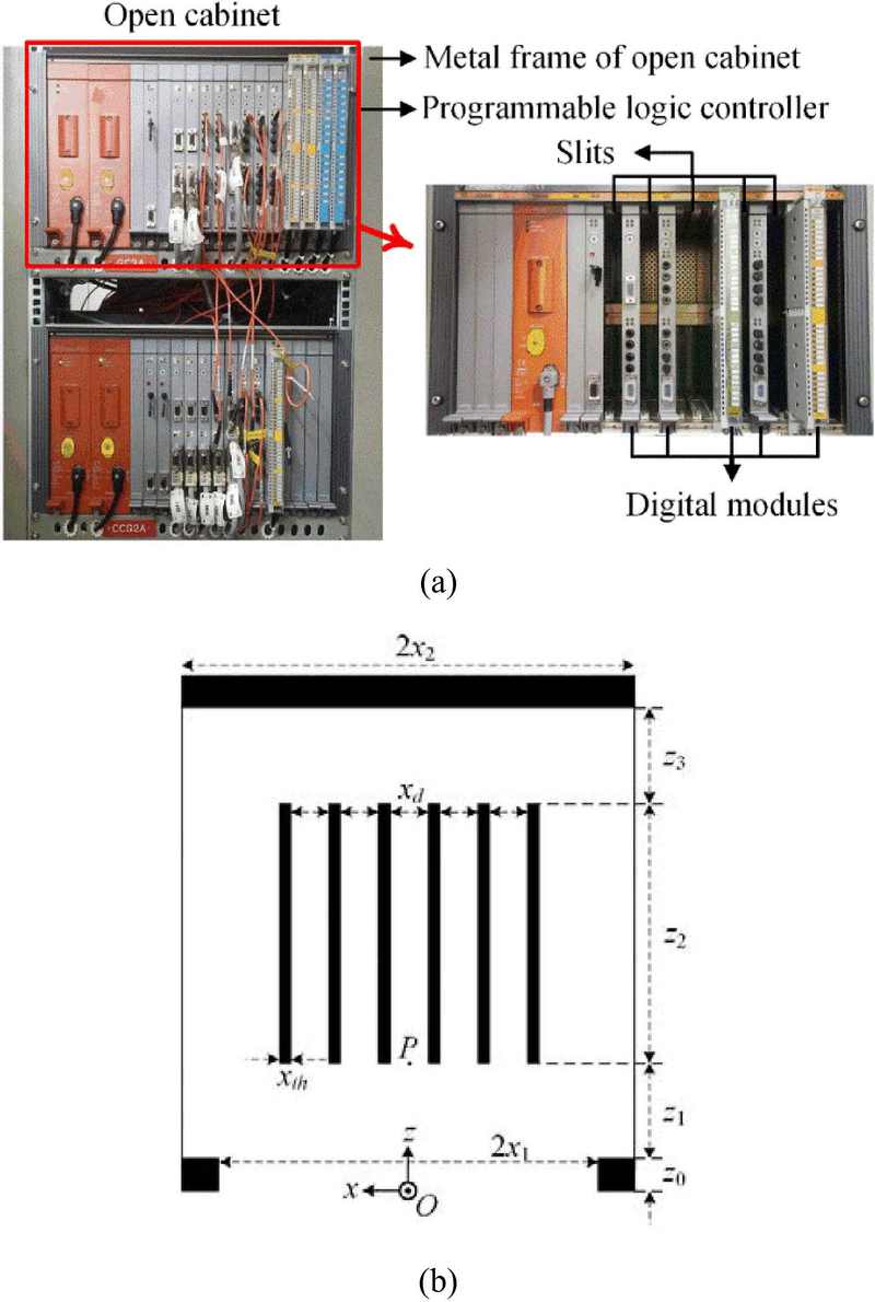
(a) Configuration of an open cabinet with inserted DMs (front view). (b) Configuration of an NPP cabinet and arrayed DMs (top view). Dimensions in the x- and z-axes are described and specified in Table 1. Point P is the representative point to capture SE values for various cases and compare them with one another.
| (1) |
Here, t0 can be determined arbitrary and was 0.354 ns in the simulation. The parameter τ was set as sqrt(2.3)/π/fmax from the commonly applied formula [10].
From z0 to z3 along the z-axis, the region can be divided into four sub-regions, and each can be represented in the same formulation. This is because the y-axis is sufficiently long, and only the x-component of the polarization is considered. In the case of z = [50, 200], the region corresponding to z1 in Figure 1, the electromagnetic field component can be expressed as follows:
| (2) |
| (3) |
| (4) |
where (= nπ/(2x2)) and () are the eigenvalues and propagation constants for the nth modes (n = 0, 1, 2, …); and η0 and k0 are the intrinsic impedance and propagation constant in free space, respectively.
3. Scattered Fields inside the Cabinet
When incident electric and magnetic fields were formed along the x- and y-axes, respectively, and transmitted into the cabinet, the electromagnetic-field patterns inside the cabinet were investigated. Figures 2(a) and (b) show the field strengths of the electric and magnetic waves at 2.4 GHz. Similarly, Figures 2(c) and (d) show the field strengths of the electric and magnetic waves at 5 GHz. The reason for using two definite frequencies is that these frequencies were applied in a wireless local area network. Moreover, these are the representative frequencies that can be utilized inside an NPP. As the incident wave of the time-shifted Gaussian waveform was converted by Fourier transform, the electric field strengths at 2.4 and 5 GHz were −46.02 and −46.66 dBV/m, respectively. As the incident wave was a plane wave in free space, the strengths of the magnetic field could be obtained by considering a difference of 120 π in the electric field strength, which is the intrinsic impedance of free space. The magnetic field strengths were −97.54 and −98.18 dBA/m at 2.4 and 5 GHz, respectively. Considering these values, the strengths of the electromagnetic fields are obtained as shown in Figure 2. The overall scattering characteristics were similar at both frequencies and relatively strong field characteristics were obtained at 2.4 GHz, even in areas not occupied by the DMs. From the difference in scale, it can be understood that the electromagnetic field strengths were slightly stronger at 2.4 GHz than those at 5 GHz.
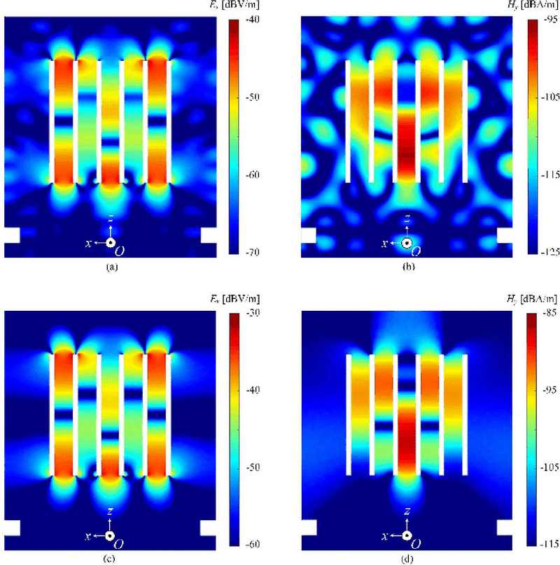
Electromagnetic field distributions inside the cabinet for 2.4 and 5 GHz: (a) Ex field distributions at 2.4 GHz, (b) Hy field distributions at 2.4 GHz, (c) Ex field distributions at 5 GHz, and (d) Hy field distributions at 5 GHz, when incident Ex is -46.02 dBV/m at 2.4 GHz and -46.66 dBV/m at 5 GHz.
4. SEs inside the Cabinet
As shown in Figure 2, the strengths of the electromagnetic waves inside the cabinet can be compared with the incident field strengths; however, it is also useful to check the electromagnetic compatibility through a more general concept called SE. The SE is a measure of the attenuation or reduction in the electromagnetic field at a defined point in space caused by the insertion of a shield between the source and the point. The SEs of the electric and magnetic fields are defined as follows [11]:
| (5) |
| (6) |
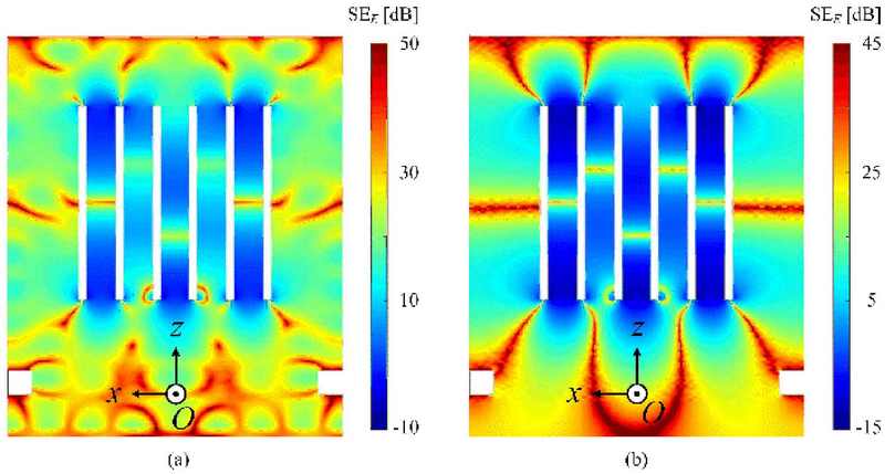
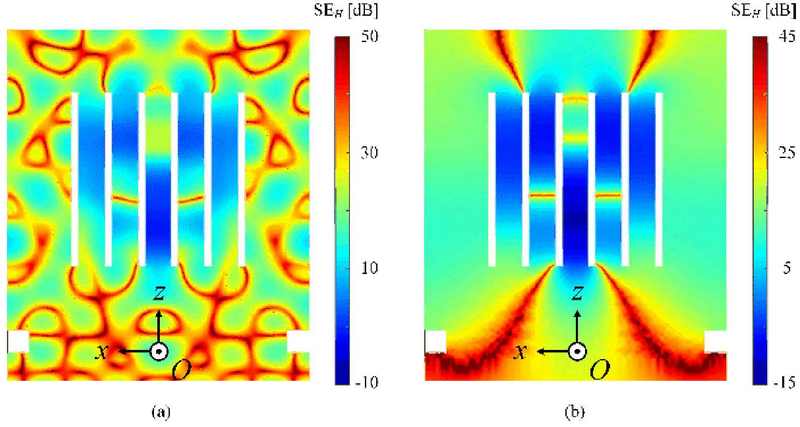
where is the given observation point; and are the electric and magnetic fields in an open cabinet, respectively; and and are the incident electric and magnetic fields, respectively. When the SE value is high, the strength of the electromagnetic waves inside the cabinet is decreased by the shield; therefore, the shielding is better. However, if the SE value is low, the shielding effect is worsened. We can infer that these results are contrary to the strengths of the electromagnetic fields, as illustrated in Figure 2. Based on Equations (5) and (6), the SEE corresponding to 2.4 and 5 GHz can be represented as shown in Figures 3(a) and (b), respectively. Only the x-component of the electric field was considered because the y- and z-components were significantly small. Because the field strengths differ for each frequency, the color bar scale is different, as shown on the right-hand side of each figure. Similarly, the SEH of the magnetic fields corresponding to 2.4 and 5 GHz are shown in Figures 4(a) and (b), respectively; the color bar scale is also different. As SE values less than 0 indicate poor shielding, it can be confirmed that the SEs at 2.4 GHz were slightly better overall. The SE between the slits appear dark blue at both frequencies, that is, the SEs were relatively low. This is because a strong electric field was induced near the corners or because the structures had a larger curvature, which is the main characteristic of electromagnetism and can be easily confirmed from Figures 3 and 4 . In other words, the effect of diffraction is well reflected in areas with large curvatures or narrow slits.
At a frequency of 2.4 GHz, the field changes were more finely detected in a small space, whereas at 5 GHz, the changes were relatively small. In addition, the SE was lower at 5 GHz than that at 2.4 GHz, as shown in Figures 3 and 4 .
As shown in Figure 1(a), even when the DMs are layered, the analysis results based on the subtle structural differences in each layer can be derived because the CST Studio suite simulator can solve 3D structures.
5. SEs with Dielectric and Magnetic Walls Applied on the Door
SEs were investigated with a dielectric or magnetic wall placed on the door of the cabinet to find a way to improve shielding. While the door of the cabinet was in free space, as shown in Figures 2-4, the SE changes were investigated considering the dielectric or magnetic material on the door, as shown in Figures 5 and 6 . The door was defined as the side with an area where x = [−300, 300] and z = [0, 50], as shown in Figures 5 and 6 . As the results at 2.4 and 5 GHz showed similar trends and the SEs of the electric and magnetic fields had no significant difference, only the SE of the electric field corresponding to 2.4 GHz is representatively explained.
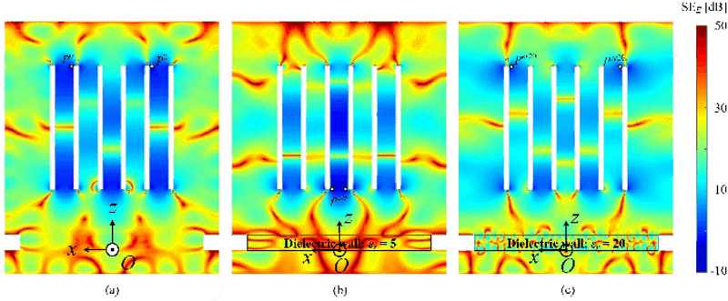
SEE for cases with (a) no dielectric wall, (b) a dielectric wall with a εr value of 5, and (c) a dielectric wall with a εr value of 20 at 2.4 GHz
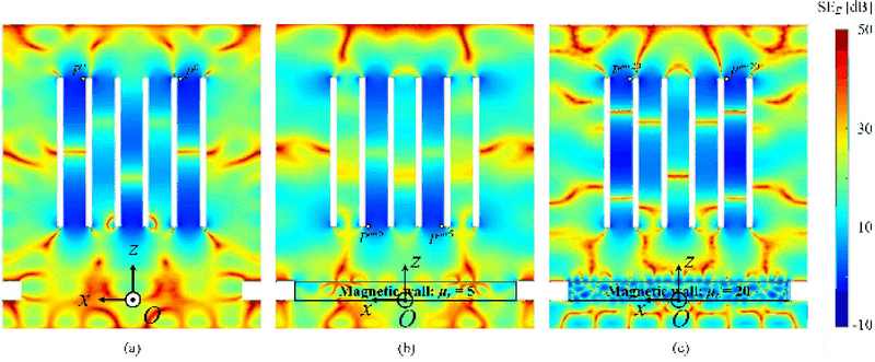
SEE for cases with (a) no magnetic wall, (b) a magnetic wall with a μr value of 5, and (c) a magnetic wall with a μr value of 20 at 2.4 GHz.
Figure 5 shows the SE values without dielectric walls and with dielectric walls of relative permittivities of 5 and 20. The higher the relative permittivity, the better is the shielding. While the shielding was not significantly improved in the middle of the slit when the permittivity was 5, it was improved in the entire slit when the permittivity was 20.
Figure 6 depicts the SE values without magnetic walls and with magnetic walls of relative permeabilities of 5 and 20. It is possible to examine the SE changes according to the relative permeability; however, it is not easy to identify a special trend, unlike that shown in Figure 5. Although the overall shielding was slightly improved when the relative permeability was 5, it was difficult to judge whether the overall shielding improved when the relative permeability was 20 compared with that without the magnetic wall.
From Figures 5 and 6 , the shielding tendencies can be understood when the SEs are analyzed using a dielectric or magnetic wall. This can be useful for designing an NPP cabinet at the application frequency. Only real values for the relative permittivity or permeability were considered, and practical values, including imaginary (loss) parts corresponding to the ohmic loss of the material, were not considered. If the analysis includes the loss term, the SE will improve owing to the overall attenuation of the electromagnetic waves inside the cabinet.
The SEE values at specific points in Figures 5 and 6 were analyzed and compared, and the results are listed in Table 2. For example, the midpoint at which the incident wave faces the front of the slot array is designated P, as shown in Figure 1. The reason for selecting this point is that it has the lowest SE value, indicating that the SE is poor. Therefore, the shielding tendencies were investigated by comparing these points.

Electric SE (SEE) at 2.4 GHz corresponding to Figures 5 and 6 at P with the minimum SEE in the entire plane inside the cabinet and the corresponding points
Once the door walls characterized by material properties are considered, the SEE values can be compared at a representative point P, and are listed in the second column of Table 2. Considering the walls in all five cases, the lowest SEE value was obtained when εr was 5, whereas the highest SEE value was indicated when εr was 20. Better SEE values were confirmed for the magnetic and dielectric walls in general. The lowest SEE values for the entire space inside the cabinet are listed in the next column of Table 2. The corresponding points are represented in the last column and shown in Figures 5 and 6 . It can be confirmed that the lowest SEE values according to the material properties differed, and the best of the lowest SEE values for all cases were found when μr was 5. If we consider the losses of realistic dielectric or magnetic materials, we can expect better SEE values.
6. SEs with Wider DM Spacings
Next, the shielding with respect to the spacing between the DMs, that is, the width of the slits, was examined. The first set of dimensions presented in Figure 1 are similar to the inner dimensions of an actual NPP cabinet with xd at a distance of 62.5 mm; however, it is also interesting to investigate the SE changes with respect to xd. The results were obtained when xd was 82.5, 102.5, and 62.5 mm, and the SEs corresponding to 5 GHz were calculated. The electric and magnetic fields were calculated, and the corresponding SEs at 5 GHz are shown in Figures 7 and 8 . The SEE values shown in Figure 7 indicate that the shielding improved as the spacing increased. Figure 7(b) shows SEE values close to −15 dB in the narrow area of the incident face of the slit. Furthermore, in Figure 7(c), SEE values slightly higher than −15 dB are found around the DMs. These results indicate that the SEs improved as the spacing xd increased. Thus, the interior of the cabinet can be freely designed from the viewpoint of the SE. However, as shown in Figure 8, the SEH according to xd does not differ significantly. Only the position where SEH appeared varied slightly; however, the overall values did not differ significantly. Moreover, because the SEE values presented in Figure 7 have already been studied, the interior of the cabinet can be designed by considering the SEE.
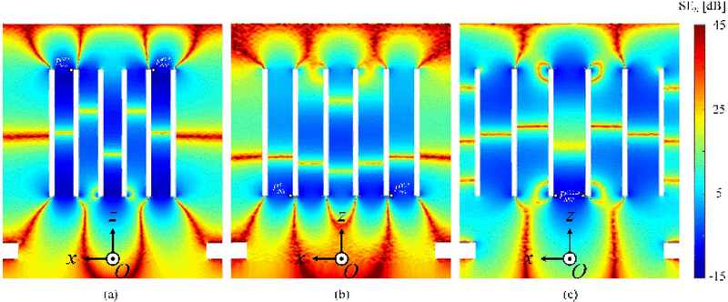
The SEE values at 5 GHz for the spacings are (a) 62.5 mm, (b) 82.5 mm, and (c) 102.5 mm between the adjacent DMs
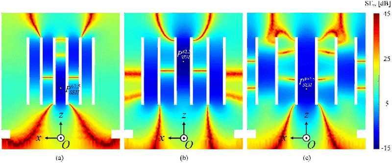
The SEH values at 5 GHz for the spacings are (a) 62.5 mm, (b) 82.5 mm, and (c) 102.5 mm between the adjacent DMs
From Figure 7, the SEE values at specific points can be compared depending on the spacing between adjacent DMs. Similar to Tables 2 and 3, the second column presents the overall SEE value at the representative point P for comparison. When xd was 82.5 mm, relatively excellent SEE characteristics were observed. The lowest SEE values across the plane inside the cabinet are presented in the third column of Table 3. The corresponding points are described in the last column, and each point can be confirmed in Figure 7. It can also be confirmed that the best SEE value was observed when xd was 82.5 mm.

Electric SE (SEE) at 5 GHz with respect to spacing, with the minimum SEE values in the entire plane inside the cabinet and the corresponding points in Figure 7
The SEH values at specific points in Figure 8 were also compared as a function of the spacing between adjacent DMs. Similar to Table 3, Table 4 lists the SEH values at P in the second column for comparison. When xd was 82.5 mm, similar to the results indicated in Table 3, relatively good SEH characteristics were observed. The lowest SEH values across the entire plane inside the cabinet are listed in the third column of Table 4. The corresponding points are described in the last column and confirmed in Figure 8. A worse SEH value was obtained when xd was 82.5 mm, contrary to the case presented in Table 3. Moreover, the lowest values did not appear at the edges of the slots, as SEH represents the SE caused by the magnetic field, which is not affected by the edge effect.
7. Conclusion
We investigated the electromagnetic scattering characteristics of an open NPP cabinet using the CST Studio Suite commercial software considering parallelly polarized incident waves. The interior of the cabinet similar to that of a realistic NPP was suggested, and application frequencies of 2.4 and 5 GHz were used. First, the electromagnetic field strengths were investigated at each frequency, and the corresponding SEs at each frequency were obtained. In the proposed structure, SEs were slightly better at 2.4 GHz than those at 5 GHz, but no notable difference was found. The SEs improved slightly when the dielectric and magnetic walls were placed on the door of the cabinet compared to the case when no such walls were applied. The SEs further improved when a lossy wall was placed. In addition, the SEs were investigated as the spacing between adjacent DMs increased. In particular, the electrical SE improved remarkably when the spacing was 82.5 mm. The results will be useful as basic data for avoiding EMI problems in open NPP cabinets.
Acknowledgments
This work was supported in part by the Korea Maritime And Ocean University Research Fund in 2021 and in part by the Basic Science Research Program through the National Research Foundation of Korea (NRF) funded by the Ministry of Education (No. 2021R1I1A3050649).
Author Contributions
Conceptualization, J.-E. Park; Methodology, J.-E. Park and J. Choo; Software, J.-E. Park; Formal Analysis, J.-E. Park and J. Choo; Investigation, J.-E. Park; Resources, J.-E. Park; Data Curation J.-E. Park; Writing-Original Draft Preparation, J.-E. Park and J. Choo; Writing-Review & Editing, J. Choo; Visualization, J.-E. Park; Supervision, J. Choo; Project Administration, J. Choo; Funding Acquisition, J.-E. Park.
References
-
J. Choo, J. Choo, and Y. H. Kim, “Shielding effectiveness of open cabinet containing digital modules using ferrite sheet,” IEEE Transactions on Magnetics, vol. 53, no. 12, pp. 1-9, 2017.
[https://doi.org/10.1109/TMAG.2017.2710947]

-
J. Choo, C. Jeong, and J. Choo, “Transverse electric scattering of open cabinet in nuclear power plants,” IEEE Antennas and Wireless Propagation Letters, vol. 15, pp. 1204-1207, 2016.
[https://doi.org/10.1109/LAWP.2015.2501368]

-
J. -E. Park, J. Choo, and H. Choo, “Electromagnetic scattering of periodic cabinets in nuclear power plants: parallel polarization,” IEEE Access, vol. 7, pp. 16487-16493, 2019.
[https://doi.org/10.1109/ACCESS.2019.2893181]

-
J. -E. Park and H Choo, “Electromagnetic interference inside the control system cabinet of a nuclear power plant from external wireless devices,” IEEE Access, vol. 9, pp. 19219-19227, 2021.
[https://doi.org/10.1109/ACCESS.2021.3054019]

-
J. Choo, J. -E. Park, H. Choo, and Y. -H. Kim, “Electromagnetic interference caused by parasitic electric-line current on a digital module in a closed cabinet,” IEEE Access, vol. 7, pp. 59806-59812, 2019.
[https://doi.org/10.1109/ACCESS.2019.2914126]

-
J. E. Park, S. Youn, J. Choo, and H. Choo, “Indoor exclusion zone analysis in a nuclear power plant with wirelessHART application,” IEICE Electronics Express, vol. 16, pp. 1-6, 2019.
[https://doi.org/10.1587/elex.16.20190204]

-
D. Jang, S. Youn, J. -E. Park, J. Choo, and H. Choo, “Electromagnetic field propagation and indoor exclusion zone analysis in a nuclear power plant,” IEEE Transactions on Electromagnetic Compatibility, vol. 62, no. 6, pp. 2386-2393, 2020.
[https://doi.org/10.1109/TEMC.2020.2970471]

-
J. Choo, H. -K. Lee, J. -E. Park, H. Choo, and Y. -H. Kim, “Analysis of electromagnetic interference between open cable trays,” IEEE Access, vol. 8, pp. 72275-72286, 2020.
[https://doi.org/10.1109/ACCESS.2020.2986516]

- CST Studio Stuie 2023, http://www.3ds.com, , Accessed September 1, 2024.
- V. Demir and A. Z. Elsherbeni, The Finite-Difference Time-Domain Method for Electromagnetics with MATLAB Simulations, Scitech Publishing, 2009.
-
S. Celozzi, R. Araneo, and G. Lovat, Electromagnetic Shielding, IEEE Wiley-Interscience, 2008.
[https://doi.org/10.1002/9780470268483]


