Development of a PLC-based functional test simulator for vessel power management system
Copyright © The Korean Society of Marine Engineering
This is an Open Access article distributed under the terms of the Creative Commons Attribution Non-Commercial License (http://creativecommons.org/licenses/by-nc/3.0), which permits unrestricted non-commercial use, distribution, and reproduction in any medium, provided the original work is properly cited.
Abstract
Ships typically use diesel generators (DGs) are power sources. However, the recent trend is moving towards various alternative power sources to save fuel and prevent environmental pollution. Existing power management system (PMS) test facilities can perform limited testing of these alternative power sources because of limitations in capacity, size, and configuration. JIG-type and actual main switchboard based simulators have been developed to overcome these challenges; however, they exhibit limited performance. We developed a PLC-based test simulator to compensate for the shortcomings of existing simulators and simulate various types of ship power grids in one system. A PLC can be applied in a power management system because of to its diverse extended functions, shortened implementation time, and ease of implementation. PMSIM-V2 is a PLC-based simulator that simulates the configurations of four types of ship power grids. Functions for generators, ACB, heavy consumers, and power calculations are programmed with add-on instructions in the form of function blocks for simulating each device. PMSIM-V2 equipped with this add-on instruction is used to test the PMS function by generating the status and power information of each device based on the control signal of the PMS. The PMS tested using the PLC-based simulator PMSIM-V2 is currently being supplied and operated on several ships.
Keywords:
PLC-based simulator, PLC-based system, Simulation system, Power management system, Functional test system1. Introduction
The power management system (PMS) of a ship manages its power quality by monitoring and controlling power busbars, generators, heavy consumers, and other related electrical elements. Energy efficiency and marine pollution regulations drive the application of vari-ous types of power generation systems in the power grid of a ship, and therefore, the PMS must be able to respond to different power grids. The existing PMS has low performance and extendibility, which makes it difficult to respond to changes. A new model must be able to respond quickly to changing markets and exhibit scalability, ease of maintenance, and flexibility in communication. Among vari-ous control systems, the programmable logic controller (PLC) developed in the late 1960s is used in various industries; further, PLCs can be applied to various applications by combining various functional modules [1]. These characteristics of the PLC help meet the re-quired conditions, and therefore, the proposed PMS model is based on the PLC.
The new model must accommodate a wide range of ship power grids, and therefore, the new PMS must verify the performance of the model using test equipment that can simulate the characteristics of these power grids. Conventional test methods involve using multiple test facilities (three-phase generators, power-conversion devices, switch boxes for signal generation, etc.) to test switchboards equipped with a PMS. However, the fixed facilities limit the PMS testing to only a few types of power grids. Thus, a test device that can simulate the functions and signals of various power grids is urgently required. In this study, we develop a PLC-based functional test simulator that can flexibly respond to various power-grid configuration conditions to test the PMS of a ship. Accordingly, we will look at existing cases and sequentially look at systems that improved the problems of the existing system.
2. Vessel Power Management System and General Test Method
2.1 PMS Function and Signal Type
The PMS of a ship is a monitoring and control system that manages the power grid to ensure a smooth power supply. The various management functions used by the PLC-based PMS to ensure a smooth power supply are listed below.
- • Start/Stop of generators according to load conditions
- • Automatic load distribution functions: Proportional load sharing/optimal load sharing/fixed load sharing
- • Power management: Bus frequency control
- • Bus tie control
- • Generator protection
- • Standby generator start/stop
The PMS collects and analyzes status signals from the generator and Main Switch Board (MSBD) and outputs appropriate commands to perform the monitoring and control. Hardwire signals are used for signal acquisition and command output, and their characteristics are listed in Table 1.
To reduce electrical problems, the PMS uses simple contacts such as relay contacts or isolated PNP/NPN-type signals for external outputs and external status signal inputs and requires the same signal format for external devices.
2.2. PMS Function Test
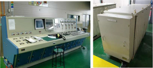
The manufacturer conducts post-production testing for the PMS. An approval test needs to be conducted in accordance with classifi-cation regulations even if the manufacturer does not conduct testing[2]. Standalone and switchboard-mounting tests are conducted for the PMS. Test generators and consoles (signal generation, including control and power) are used as test support devices. The output specifications of the test device are AC450V, 60 Hz for the test console, and 440V, 60 Hz, and 37 kW for the test generator (3set), as shown in Figure 1.
Although using actual devices afford certain advantages; their fixed configurations and specifications make it impossible to conduct tests smoothly when the specifications are exceeded. Thus, a new and supplemented test apparatus is required, and the required func-tions are listed in Table 2.
3. Development of PMS Functional Test Simulator
3.1 JIG-Type Testing Device
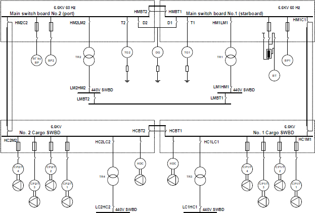
A JIG-type testing device comprises status lamps and status switches, offering advantages of simple operation and low manufactur-ing costs. An LNG carrier built by a domestic shipbuilder is the power distribution system to be simulated. The single-line diagram (SLD) (of the power grid that the PMS must manage is shown in Figure 2.
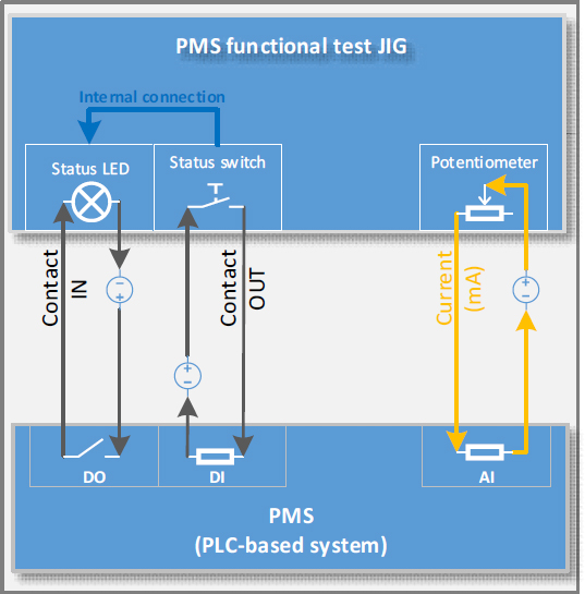
The JIG-type testing device is manufactured by printing the SLD of the power grid on a large flat plate and installing a switch and LED for the status signal at the position of the supervisory control element (Generator, bus tie, circuit breaker, etc.) on the SLD. An analog signal (4–20 mA, current signal) with the bus voltage and current is generated by combining a fixed resistor and potentiometer. A complete-status JIG-type LED plate is shown in Figure 3.
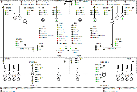
Power network status display area in the JIG-type PMS functional testing device (excluding the switch part)
During the test, the switch is set to a position corresponding to the initial state before operating the PMS. Subsequently, when the LED is turned on as an output from the PMS, the corresponding status switch is manipulated to output a signal to the PMS. The signal connection of the JIG-type testing device is shown in Figure 4.
In the JIG-type testing method, the input and output of the signal needs to be handled directly by the operator. Therefore, it is difficult to distinguish between continuous reactions and very short signals (e.g., a governor control signal, i.e., a signal of several tens of milli-seconds) that may be output. A complementary circuit is required to prevent this problem; however, this circuit is not suitable because of the nature of the JIG-type testing device as it is a one-time device (it needs to be newly manufactured when the target is changed).
3.2 PLC-Based Functional Testing Simulator with Main Switchboard: PMSIM-V1
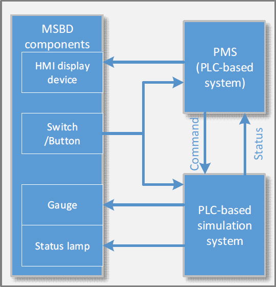
A PLC can be used in a variety of applications, including test systems, sequential controls, and control systems[3][4][5]. The simula-tion system PMSIM-V1 is developed by combining this highly usable PLC with the MSBD. PMSIM-V1 includes a combination of the MSBD manual operation panel and a PLC. The PLC is responsible for simulating the generators, circuit breakers, and buses, etc. This system is based on the operation of three DGs (diesel generators), and the configuration concept is shown in Figure 5.
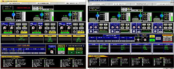
PMSIM-V1 simulates both types of power grids and displays the related information in the HMI (human-machine interface), as shown in Figure 6. Power grids with different power capacities are simulated using HMI parameter settings, and the setting factors are presented in Figure 7.
PMSIM-V1 can simulate the power distribution system according to the MSBD operation without an external test support device. Thus, the PMS function can be checked using the MSBD test procedure. PMSIM-VI is based on a physical MSBD, and therefore, it has limitations in terms of the physical configuration and requires a large installation space. Further, it is difficult to simulate the power grid without using a DG.
3.3 Fully PLC-based PMS Functional Test Simulator: PMSIM-V2
The JIG-type testing method offered advantages of low cost and simple configuration, whereas PMSIM-V1 offered advantages of actual operation sensitivity and generator specification change. However, both methods have limitations when configured and used as functional test simulators for PMS.
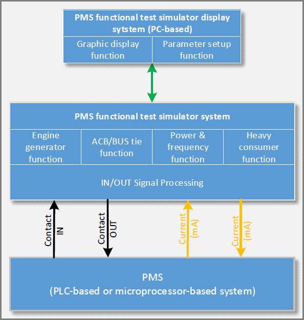
PMSIM-V2 comprises a PLC and HMI and has greater flexibility and expandability than these existing systems. In other words, PMSIM-V2 can implement generators and switchboards (buses, circuit breakers, etc.) using PLC logic and HMI programs, enabling it to respond flexibly to various systems. The signal linkage relationship between the PMSIM-V2 and PMS is shown in Figure 8.
PMSIM-V2 configures the physical IO channel to support both microcontroller-based and PLC-based PMS.
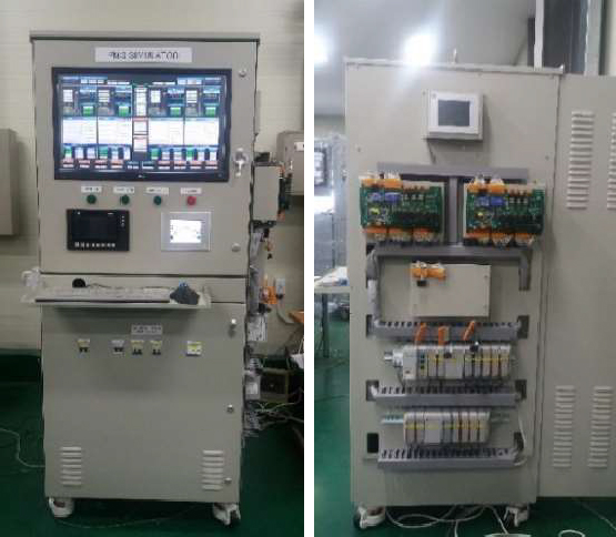
The size of PMSIM-V2 is 1800 × 750 (W × H × D, mm). Photographs of the external unit of the PMSIM-V2 are presented in Figure 9. The PMS under testing is mounted on the rear or outer side of the panel, which provides greater space utilization and operational convenience than that of the existing test facilities.
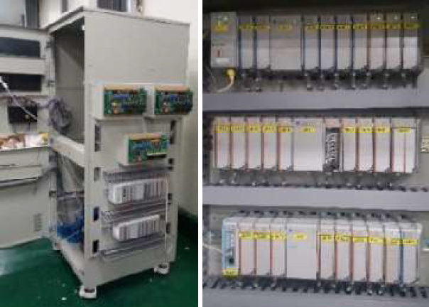
PLC-based PMS functional test simulator: Outer shape with PMS units(Left) and installed PMSIM-V2 PLC system(Right)
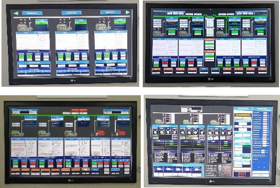
PMSIM-V2 is equipped with various power grid simulation logic written in ladder diagrams. Each power grid model is selected and operated in the operation HMI. The programmed simulated power grid for PMS testing is shown in Figure 10.
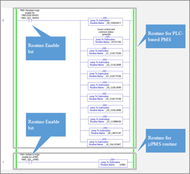
The control program of PMSIM-V2 written using a ladder diagram includes one main routine and multiple subroutines. The subrou-tines operate within the main routine and are activated according to monitoring signals or calculation results. The logic of PMSIM-V2, which calls the subroutine within the main routine, is shown in Figure 11 (partial). Using this programming method, various power-grid simulations can be conducted without changing the program.
4. Simulation function blocks of PMSIM-V2
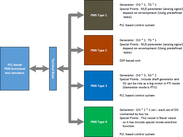
Figure 12 shows that the PMSIM-V2 in the form of a compact cabinet has excellent space utilization compared to that that of previ-ous simulators and test equipment. Further, the four types of power grids implemented in a single system can be operated easily by se-lecting them from the HMI menu. The power grid simulation of the ship is illustrated in Figure 13.
Devices and appliances such as generators, ACB, and heavy consumers are created as add-on instructions (user-defined function blocks) and used to simulate the power grid in the control program of the PMSIM-V2.
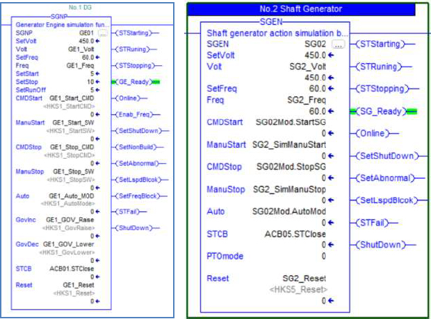
Generator simulation instructions SGNP and SGEN have functions related to generator operation. SGNP includes an in-crease/decrease function for voltage and frequency, changing the voltage and frequency according to the governor control signal of the PMS. The instruction formats for the SGNP and SGEN are presented in Figure 14, with one instruction simulating a single generator.
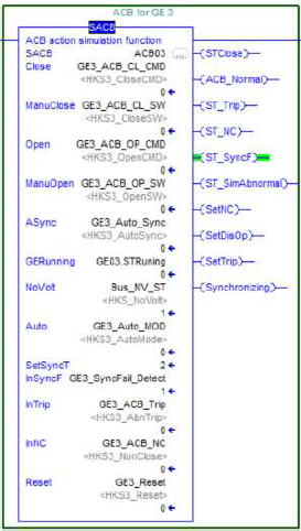
The instruction ACB simulates a circuit breaker that connects a bus and a generator. This instruction performs necessary actions and signal simulations, such as generating status signals for command input and alarm generation according to alarm situation settings. The instruction form for ACB is shown in Figure 15.
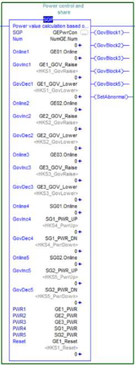
The instruction SGP simulates the power values of up to five online state generators to inspect the power management function of the PMS. The power of the generator is simulated using the governor control signal received from the PMS. The change in the power gen-erated by the individual generators and the load transfer between the operating generators are simulated in a single instruction. The in-struction form for SGP is shown in Figure 16.
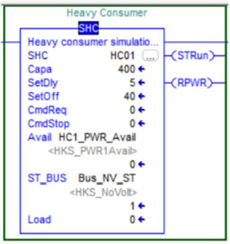
The instruction form for SHC for heavy consumers is shown in Figure 17. This instruction adds a defined power consumption to the total amount of power based on the activation of the power available signal received from the PMS.
Thus, PMSIM-V2 has advantages of a simplified device configuration and easy power grid change. Further, expansion can be easily achieved by adding I/O modules to the hardware and instructions for each device in the software. The supply record of the PMS, which performed the performance verification tests using this simulation device, is listed in Table 4.
5. Conclusion
PMSIM-V2, which is a highly flexible and scalable PLC-based simulator, was developed to address the limited performance of exist-ing marine PMS performance test facilities. PMSIM-V2 is equipped with a program that can respond to four types of distribution sys-tems and five types of PMS. Therefore, it can simulate various power grids and achieve convenient operation. Further, a cabinet-type exterior with an area of 800 × 750 mm was designed so that the PMS to be tested could be installed inside or outside, eliminating the need for an external space for the test object. Thus, PMSIM-V2 has considerable advantages over existing test facilities, including vari-ous power grid simulations, small installation space, and low configuration costs.
However, PMSIM-V2 has further improvements, as shown in Table 5.
Author Contributions
Conceptualization, Methodology, Software, Data Curation, Writing-Original Draft Preparation, J. H. Jung; Writing-Review & Editing, S. J. Cho.
References
- PLC (Programmable Logic Controllers) market, INNOPOLIS Foundation, 2018 (In Korean).
- Rules for the Classification of Steel Ships, Part 6: Electrical Equipment and Control System, Korea register, 2022.
- J. M. Galvez, M. L. M. Duarte, I. D. Seschini, and L.P. R. de Souza, “A PLC based test bench for experimental analysis of whole-body vibration (WBV) effects on humans,” ABCM Symposium Series in Mechatronics, vol. 3, pp. 177-186, 2008.
- M. A. Khattak, “PLC based intelligent traffic control system,” International Journal of Electrical & Computer Sciences IJECS-IJENS, vol. 11, no. 6, pp. 69-73, 2011.
- B. Schofield, J. Borrego, and E. Blanco Viñuela, “Continuous integration for PLC-based control system development,” 18th International Conference on Accelerator and Large Experimental Physics Control Systems, pp. 478-483, 2022.


