Experimental study to determine the emissivity of fire door finishing materials according to calorimetry method
Copyright © The Korean Society of Marine Engineering
This is an Open Access article distributed under the terms of the Creative Commons Attribution Non-Commercial License (http://creativecommons.org/licenses/by-nc/3.0), which permits unrestricted non-commercial use, distribution, and reproduction in any medium, provided the original work is properly cited.
Abstract
To develop a numerical calculation procedure for designing fire doors for ships, this study focused on measuring the emissivity of surface-finished steel materials, including Electro Galvanized Iron (EGI) steel, Galvanized Iron (GI) steel, and stainless steel. To calculate the emissivity, an analytical method was used to measure changes in steel temperature using data collected from the electric heating furnace and specimen. The steel structure design guidelines in Eurocode 3 (EN1993-1-2) recommend a constant emissivity of εm = 0.7 for carbon steel. However, the test results indicated values less than 0.7 for the surface temperature of EGI steel plates below 330 °C and GI steel plates below 440 °C. Notably, the GI steel plate test results aligned well with previous studies by Elich (1990) and Jirku (2015), indicating that Zn plating can delay temperature increases and can reduce surface emissivity. Paloposki & Liedquist (2006) results were identical to those of stainless steel plate 304 2B.
Keywords:
Emissivity, EGI steel, GI steel, Stainless steel, Heat transfer1. Introduction
Regarding fire protection, buildings and ships ensure the safety of individuals and structures from fire hazards by designing fire-resistant structures and fire compartmentalization. In buildings, prescriptive rules and performance-based design methods are used in parallel with the design of fire-resistant structures. Regulations and guidelines for fire-resistant structure design methods have been developed through the formulation of engineering models based on experimental data over a long period of time. Additionally, a code was developed for designers to easily check the results of the temperature distribution calculations and structural behavior based on fire exposure conditions.
Representative fire-resistant structural design codes include the International Building Code (IBC) used in North America and the Eurocodes used in the European Union. In fire-resistant design codes, if the existing specifications cannot accommodate the use of new materials or structures, a performance-based design method is permitted as an alternative. This approach relies on compartmental characteristics and fire loads to ensure safety and compliance[1][2].
Even on ships, there are safety of life at sea (SOLAS) regulations corresponding to fire-resistant design codes. Unlike in buildings, using combustible materials is strictly restricted, considering the isolated environment of the sea[3]. Additionally, most of the materials used must be non-combustible. Bulkheads and decks corresponding to steel structures are divided into fire protection categories according to fire-resistance classes A, B, and F, based on the purpose of the compartment[4].
Alternative design methods for buildings are permitted when SOLAS regulations do not accommodate them. Related details include SOLAS Regulation II-2/17 (Alternative Design or Layout) and International Maritime Organization (IMO) Maritime Safety Committee (MSC)/Circ. 1002 (Guidelines on alternative design and arrangements for fire safety), IMO MSC.1/Circ.1319 (2009) for large fire doors, and the International Association of Classification Societies (IACS) UI-FTP 3 fire doors[3][5][6][7].
Steel structures constitute a significant portion of the industry. However, compared to buildings, there is insufficient information available on fire research and heat-transfer-related parameters associated with steel structures. For example, the contents of the UI FTP CODE/Fire Door 3.6 heat transfer analysis adopted by the IACS are as follows[7]:
| (1) |
| (2) |
where qc and qr represent convection and radiative heat flux, respectively, hc represents convection heat transfer coefficient, σ represents Stefan-Boltzmann constant, ε represents emissivity coefficient, Ts represents surface temperature, and T∞ represents furnace or ambient temperature.
Equations (1) and (2) are included in the equivalent boundary conditions[7].
| (3) |
where the equivalence coefficient Heq is based on the unknown surface temperature. However, it can be calculated as part of a finite-element analysis using an emissivity coefficient that is appropriately calibrated with the fire test results[7].
In Eurocode, information and recommended values concerning heat transfer parameters are provided. However, in the technical regulations governing the evaluation and approval of large fire doors, as adopted by the IMO and IACS, only boundary conditions for heat transfer analysis are specified, and there is a lack of information on the heat transfer parameters. Furthermore, there is no clear distinction as to whether the emissivity coefficient pertains to the surface emissivity coefficient. The Eurocodes concern columns and beams, which are the main structural parts of buildings, and do not include information regarding fire doors. The thermal boundary conditions of the columns and beams differ from those of fire doors. Additionally, because the steel materials are different, it is necessary to develop a numerical calculation model based on the surface emissivity and heat transfer of the fire door materials.
Therefore, in this study, a high-temperature test was conducted using the calorimetric method to derive the required surface emissivity value for the development of a numerical calculation procedure for marine fire doors. The test procedures and correlation equations are obtained from previous studies by Paloposki & Liedquist (2006) and Sadiq (2013)[8][9]. For the specimens, the emissivity values for each material were obtained in the specimen surface temperature range of 200–600 ℃ for three types of fire door finishing materials, EGI steel, GI steel, and stainless steel. The GI steel emissivity values showed good agreement with those of previous studies (Elich, 1990; Jirku, 2015), whereas the stainless steel exhibited a similar trend to the results of Paloposki and Liedquist (2006)[10]-[12].
2. Heat Transfer Processes
2.1 Convection Heat Transfer
The heat transfer condition of natural convection was applied inside the electric heating furnace, and the convective heat transfer between the air inside the electric heating furnace and the subject was generally expressed as follows[8][13]:
| (4) |
Where hc represents the convection heat transfer coefficient between the fluid and specimen, A1 represents the surface area of the specimen, and T1 and T2 represent the specimen temperature and internal temperature of the electric heating furnace, respectively.
By identifying the geometric shape of the specimen and the flow conditions around the specimen to be tested, an appropriate dimensionless correlation for determining the convection coefficient can be obtained. The key parameters for establishing these correlations are the Nusselt (NuL), Prandtl (Pr), and Rayleigh (RaL) numbers[8][13].
| (5) |
Where hc represents the convection heat transfer coefficient, Lc represents the characteristic dimension of the test specimen, and kair represents the thermal conductivity of the fluid.
The convection heat transfer coefficient hc was obtained using Equation (6)[9][13].
| (6) |
The Rayleigh number RaL is defined as follows :[9][13]
| (7) |
where GrL represents the Grashof number and Pr represents the Prandtl number.
- g represents the acceleration of gravity (9.81 m/s2).
- β represents the volumetric thermal expansion coefficient (K-1).
- Lc represents the characteristic dimension of the test specimen.
- ν represents momentum diffusivity, and α represents the thermal diffusivity.
The correlation equation for laminar flow on a vertical plate is expressed by Equation (8) and was provided by Churcill and Chu; thus, it can be applied to the entire area RaL [13][14].
| (8) |
2.2 Radiant Heat Transfer
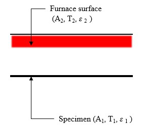
The radiative heat transfer model used in this test was based on the net radiative heat flux equation adopted in Eurocode. This is derived from the heat transfer theory of two opposite parallel infinite plates, in which the gas combustion products are not involved in the heat transfer process[2][13].
The radiative heat transfer model shown in Figure 1 is expressed by Equation (9).
| (9) |
2.3 Energy Balance for the Test Specimen
When the test specimens were exposed to the high-temperature environment of the heating furnace, the temperature increased. The net change rate of the internal energy for the test specimen was equal to the difference between the total heat energy entering and leaving the specimen and is expressed as Equation (10)[13][14].
| (10) |
where ∆Est represents the rate of change in the internal energy of the test specimen as the temperature increases and decreases, and the shape of the steel specimen can be assumed to be a closed system, as shown in Equation (11)[13][14].
| (11) |
where m represents the mass of the test specimen, Cp represents the specific heat of the test specimen, t represents time, and dT1/dt represents the rate of temperature change in the test specimen.
The heat transfer from the electric heating furnace in a high-temperature environment to the test specimen flows into the test specimen owing to convection and radiation, and the net heat transfer is shown in Equation (12)[8][13][14].
| (12) |
Therefore, by combining Equations (11) and (12), Equation (13) can be expressed as follows[8][9]:
| (13) |
From Equation (13), the emissivity ε1(T1) can be solved as the following Equation (14)[8][9].
| (14) |
In Equation (14), the emissivity of a material can be determined from the test data if m1 , A1 and Cp are known; T1(t) and T2(t) are measured and recorded during the test; and hc is computed using the procedure presented in the previous section[8][9].
3. High-temperature Test
3.1 High-temperature Test for Emissivity Measurement
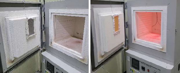
The high-temperature test for the emissivity measurement used an electric furnace with internal dimensions of 400 × 400 × 400 mm, as shown in Figure 2. Emissivity measurement specimens were prepared for the three types of steel (GI steel, EGI steel, and stainless steel) used in the fire doors of ships, as listed in Table 1.
The thermocouple for the temperature measurement was positioned at the center of the specimen's length, and another thermocouple was placed near the center of the specimen to measure the temperature inside the heating furnace. Special precautions were considered to prevent heat from penetrating areas other than the specimen surface. This was achieved by enveloping the specimen with a ceramic fiber pad, as illustrated in Figure 2.
During the 30-minute test period, data measurements were acquired at 1-second intervals to facilitate the application of relevant equations to the test results. Similar to the previous study by Sadiq (2013), the 10-second average value of the acquired data was used to calculate the convection heat transfer coefficient and surface emissivity.
The test was conducted on one specimen each for approximately 25 to 30 min, with the heating temperature set to 800 °C. A notable difference from previous studies by Paloposki and Liedquist (2006) and Sadiq (2013) is that, as shown in Figure 2, three types of steel plates were affixed to the furnace wall before the test. Additionally, the temperatures of both the furnace and the test specimen were continuously monitored and measured simultaneously throughout the test.
3.2 Calculation of Convection Heat Transfer Coefficient and Surface Emissivity of Specimen
The information required to calculate the convection heat transfer coefficient is listed in Table 2, following the same order as that shown in the Excel spreadsheet used in a previous study by Sadiq (2013). The surface temperature of specimen T1 and the environmental temperature of the heating furnace T2 were collected during the heating test of each specimen. The thermophysical properties of air, including ν (kinematic viscosity), α (thermal diffusivity), k (thermal conductivity), and Pr (Prandtl number), were determined using the film temperature Tf (Equation 7). These values were referenced from the data provided in the appendix of Holman's book (2008). The Nusselt number NuL was calculated using Equation (5), the convection heat transfer coefficient hc was calculated using Equation (6), and the Rayleigh number RaL was calculated using Equation (7)[8][9][15].
Table 2 lists the calculation sequence and results for obtaining the convection heat transfer coefficient using the experimentally measured temperatures of the heating furnace and the EGI steel plate specimen. Owing to the vast data, only a portion of the calculations is presented. In previous studies, for specimens with a length of 50 mm, the convective heat transfer coefficient was in the range of (8–10) W/m2K [8].
The convection heat transfer coefficient is influenced by the specific flow conditions and temperature difference between the specimen and furnace environment. Consequently, it is not universally applicable under all test conditions. That is, it is crucial to recognize that the convection heat transfer coefficient calculated through the electric heating furnace test, which typically represents natural convection conditions, may not be suitable for application in gas heating furnace tests where forced convection conditions prevail.
3.3 Surface Emissivity Calculation
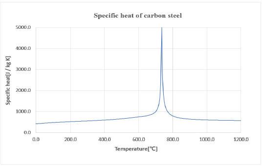
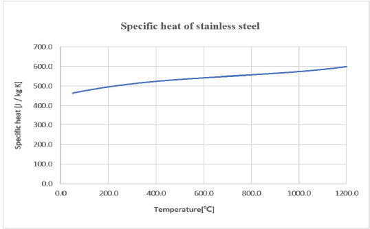
To determine the emissivity ε of EGI, GI, and stainless steel plate specimens, data obtained from the high-temperature test, including surface temperature and furnace temperature, were used. The specific heat change in the test specimen with the temperature was based on the values recommended for carbon steel and stainless steel in Eurocode 3, as shown in Figures 3 and 4. In addition, the masses of the test specimens were measured before testing[12]. The convection heat transfer coefficient, calculated using Equation (8), was applied to the spreadsheet for the emissivity calculation. Table 3 outlines the steps necessary for calculating the emissivity of an EGI steel plate using the measured surface and heating temperatures of the plate along with the convection heat transfer coefficient obtained from Table 2 and Equation (6)[9].
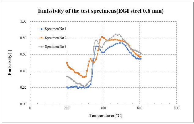
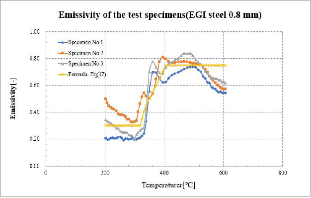
Figure 6 shows the variation in the calculated emissivity as a function of temperature for the EGI steel plate 0.8 mm specimen. Within the temperature range of 200–320 °C, an emissivity value of 0.3 was calculated for the EGI steel plate.
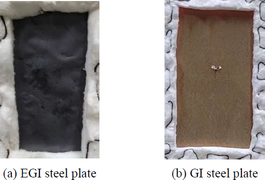
However, as the surface temperature of the specimen reached 340 °C, there was a rapid increase in emissivity and the emissivity was maintained at 0.75 within the range of 400–530 °C. Subsequently, it was observed to gradually decrease after 530 °C before increasing again. These emissivity change characteristics of the EGI steel plate suggest that once surface temperature exceeded 300 °C, the zinc plating began to separate from the steel plate, forming a protective film. This phenomenon is likely attributed to the lower zinc adhesion and differences in plating methods compared with GI steel. Upon completion of the experiment, the presence of a zinc-plated protective film on the surface of the specimen was confirmed (Figure 5). The higher initial emissivity values calculated for Specimens 2 and 3 were believed to be a result of the residual heat affecting the specimens owing to continuous testing.
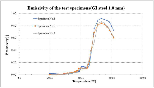
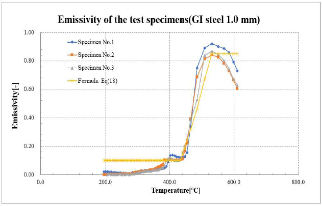
Figure 7 shows the variation in emissivity calculated with respect to the temperature of the GI steel 1.0 mm specimen. The calculated emissivity was maintained below 0.1 when the surface temperature of the specimen was below 440 °C. However, as the surface temperature exceeded 440 °C, the emissivity value began to increase rapidly, reaching 0.87 when the surface temperature was approximately 530 °C. Subsequently, the emissivity gradually decreased before slowly rising again when the specimen surface temperature reached approximately 640 °C.
In Figure 7, the sharp increase in emissivity is related to the fact that the melting point of zinc is 420 °C, and at this temperature, the melting of the zinc plated on the specimen is clearly visible[16].
Figure 8 shows the test outcomes for the galvanized steel plates, as reported by Elich (1990). This validates that the computed emissivity results for the GI steel 1.0 mm specimen in this test aligned well with the emissivity results from Elich (1990) for n (new sheet).
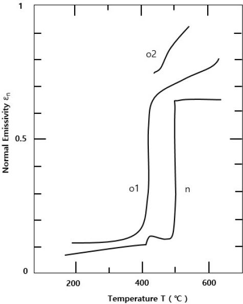
The normal emissivity εn of galvanized steel measured at increasing temperature T. n--new sheet, o—old sheet[10]
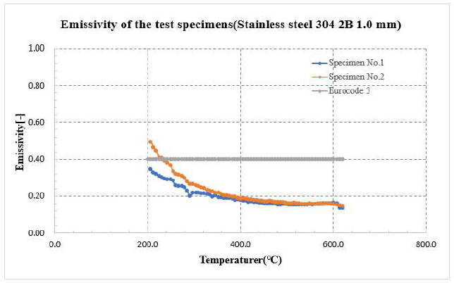
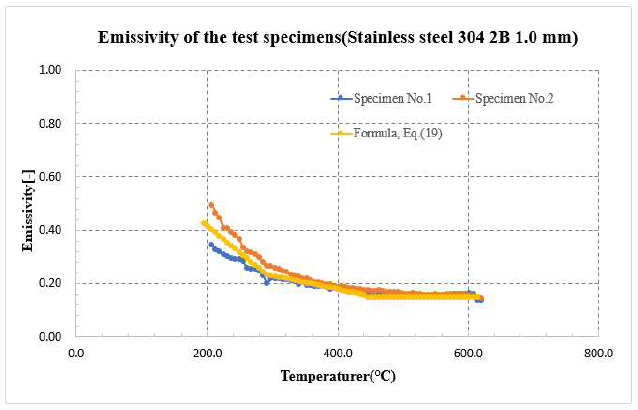
Figure 9 shows the variation in emissivity calculated with respect to the heating temperature for a stainless steel 304 2B 1.0 mm specimen. The emissivity of the specimen appeared to follow a trend of gradually decreasing as the surface temperature increased. This trend differed from Eurocode 3, which recommends a constant value of 0.4 for stainless steel emissivity. However, this aligned with Paloposki and Liedquist’s (2006) results.
4. Conclusion
To develop a numerical calculation procedure for designing fire doors for ships, high-temperature experiments using the calorimetric method were conducted on three types of steel, such as EGI, GI, and stainless steel. The emissivity calculation results were obtained in the range of specimen surface temperature of 200–600 °C, resulting in the following conclusions.
- 1) The emissivity value ε of EGI steel plate can be broadly divided into three temperature ranges based on the surface temperature Ts. We propose the following equation for the emissivity value ε of EGI steel plate, as shown in Equation (17). A plot of Equation (17) along with the results obtained from the proposed method is shown in Figure 10.
| (17a) |
| (17b) |
| (17c) |
- 2) The emissivity value ε of GI steel plate can be broadly divided into three temperature ranges based on the surface temperature Ts., We propose the following equation for the emissivity value ε of GI steel plate, as shown in Equation (18). A plot of Equation (18) along with the results obtained from the proposed method is shown in Figure 11.
| (18a) |
| (18b) |
| (18c) |
- 3) The emissivity value ε of stainless steel plate can be broadly divided into three temperature ranges based on the surface temperature Ts. We propose the following equation for the emissivity value ε of stainless steel plate, as shown in Equation (19). A plot of Equation (19) along with the results obtained from the proposed method is shown in Figure 12.
| (19a) |
| (19b) |
| (19c) |
Finally, the emissivity measurement experiment based on the high temperature test method conducted in this study had a limitation in that it was difficult to derive the emissivity value below 200 °C, and based on the emissivity value determined through this experiment, research on the development of numerical calculation procedures for predicting the temperature rise of fire doors for ships will be conducted in the future.
Author Contributions
Conceptualization, T. J. Choi and Y. T. Kim; Methodology, T. J. Choi; Experiment, T. J. Choi; Formal Analysis, T. J. Choi; Investigation, T. J. Choi; Resources, T. J. Choi; Data Curation T. J. Choi; Writing-Original Draft Preparation, T. J. Choi; Writing-Review & Editing, Y. T. Kim; Visualization, T. J. Choi; Supervision, Y. T. Kim; Project Administration, Y. T. Kim; Funding Acquisition, Y. T. Kim.
References
- ICC, International Building Code (IBC code), 1st Edition, 2020.
- CEN, Eurocode 1: Action on structures - Part 1-2(EN1991-1-2): General action – Action on structures exposed to fire, 2002.
- IMO, International Convention for the Safety of Life at Sea(SOLAS), 1974.
- IMO, MSC/Res. 307(88) Adoption of the international Code for application of Fire Test Procedures (2010 FTP code), 2012.
- IMO, MSC/Circ. 1002 Guidelines on alternative design and arrangements for fire safety, 2001.
- IMO, MSC.1/Circ.1319 Recommendation for the evaluation of fire performance and approval of large fire doors, 2009.
- IACS, UI FTP 3 Fire door, 2010.
- T. Paloposki and L. Liedquist, Steel emissivity at high temperatures, VTT RESEARCH NOTES 2299, VTT Building and Transport, Finland, 2005.
-
H. Sadiq, M. B. Wong, J. Tashan, R. A. Mahaidi, and X. L. Zhao, “Determination of steel emissivity for the temperature prediction of structural steel members in fire,” Journal of Materials in Civil Engineering, vol. 25, no 2, pp. 167-173, 2013.
[https://doi.org/10.1061/(ASCE)MT.1943-5533.0000607]

-
J. J. Ph. Elich and A. F. Hamerlinck, “Thermal radiation properties of galvanized steel and its importance in enclosure fire scenarios,” Fire Safety Journal, vol. 16, no. 6, pp. 469-482, 1990.
[https://doi.org/10.1016/0379-7112(90)90023-8]

-
J. Jirku and F. Wald, “Influence of zinc coating to a temperature of steel members in fire,” Journal of Structural Fire Engineering, vol. 6, pp. 141-146, 2015.
[https://doi.org/10.1260/2040-2317.6.2.141]

- CEN, Eurocode 3: Design of steel structures - Part 1-2(EN1993-1-2): General rules – Structural design, 2005.
- F. P. Incropera, D. P. DeWitt, T. L. Bergman, and A. S. Lavine, Principles of Heat and Mass Transfer, 8th Edition: Textbooks, Wiley, 2020.
- Y. A. Cengel, A. J. Ghajar, Heat and Mass Transfer, 4th Edition: McGraw-Hill, 2020.
- J. P. Holman, Heat Transfer, 10th Edition: McGraw-Hill, 2010.

