A novel proposal for a marine fuel cell system utilizes LNG as a sustainable and green fuel for the future of shipping
 ; Hokeun Kang††
Contributed by footnote: *Co-first author: Author who have same contribution in this paper
Copyright © The Korean Society of Marine Engineering
This is an Open Access article distributed under the terms of the Creative Commons Attribution Non-Commercial License (http://creativecommons.org/licenses/by-nc/3.0), which permits unrestricted non-commercial use, distribution, and reproduction in any medium, provided the original work is properly cited.
Abstract
Maritime transportation, representing over 80% of global shipping, has emerged as a significant contributor to environmental emissions. Consequently, emission mitigation strategies are crucial for preserving our maritime ecosystems. This study proposes an innovative integrated propulsion system utilizing solid oxide fuel cells (SOFCs), proton exchange membrane fuel cells (PEMFCs), and waste heat recovery, fueled by liquefied natural gas (LNG), to achieve high efficiency and minimal emissions. Utilizing the cold energy from LNG, the system supports a CO2 capture mechanism from exhaust gases. Through the integration of gas turbine (GT), organic Rankine cycle (ORC), and steam Rankine cycle (SRC), the cold energy of LNG and waste heat of SOFC are efficiently converted into usable power. To address vessel startup delays and maneuvering periods, SOFCs and PEMFCs are integrated into the system. The CO2 capture system is designed to comply with international and local regulations. Thermodynamic analysis, conducted using ASPEN HYSYS V12.1, includes the development of equations based on the laws of thermodynamics to evaluate system performance indicators and optimize component design. The proposed system demonstrates energy and exergy efficiencies of 68.76% and 33.58%, respectively, with waste heat recovery cycles contributing an additional 2100.42 kW, equivalent to 35.6% of the total output. A parametric study reveals that varying current density impacts energy efficiency, highlighting the system's sensitivity to operational parameters. This integrated approach, harnessing LNG cold energy and waste heat recovery for CO2 capture, aligns with International Maritime Organization (IMO) emissions regulations, facilitating environmentally sustainable shipping practices.
Keywords:
Novel propulsion system, SOFC, PEMFC, Emission control, CO2 capture1. Introduction
Maritime transportation serves as a cornerstone of global trade and supply networks, yet its extensive operations also generate significant environmental pollution [1]. Consequence, maritime transportation are responsible for nearly 30% of nitrogen oxide (NOx) emissions and approximately 2.5% of the entire carbon dioxide emissions, exerting a considerable impact on air quality [2]. In response to these environmental concerns, the IMO and local maritime authorities have enforced strict emissions regulations and standards, including IMO 2020 [3], MARPOL 73/78 [4], and IMO tier I, II, III [5][6], etc. As a result, the maritime sector is increasingly shifting towards cleaner energy alternatives, with liquefied natural gas (LNG) emerging as a particularly promising transitional fuel option [7].
LNG [8] presents a viable alternative fueled by its lower sulfur content, widespread accessibility, and relatively cost-effective energy expenditure. Utilizing LNG as a fuel source substantially reduces 75-90% nitrogen oxide emissions, 25% carbon dioxide emissions, and effectively eliminates sulfur oxide and particulate matter emissions [9].
Primarily composed of methane (CH4), liquefied natural gas (LNG) undergoes a transformation into liquid form at temperatures nearing -260°F (-162°C). However, the subsequent process of regasification, necessary for end-user applications, releases a significant amount of usable cold energy. This phase emits approximately 830 kJ/kg of cold energy into the environment, potentially affecting nearby ecosystems. Harnessing the frigid energy derived from LNG within integrated cycles not only enhances system efficiency but also enables a diverse array of applications, including its utilization as the primary fuel for fuel cells, gas turbines (GT), traditional diesel engines, or within the maritime industry.
Fuel cells, such as PEMFCs and SOFCs, offer promising solutions for various applications, including marine propulsion systems. While PEMFCs are known for their high-power density and fast start-up times, SOFCs distinguish themselves through their efficiency, fuel flexibility, and ability to operate at high temperatures. In marine applications, SOFCs [10] present several advantages over other types of fuel cells. Firstly, SOFCs can utilize a variety of fuels, including hydrogen, methane, and natural gas, making them adaptable to different fuel availability scenarios encountered in maritime settings. This versatility reduces reliance on specific fuel sources and enhances operational flexibility. Additionally, SOFCs operate at high temperatures, typically from 550°C - 1000°C, which allows for efficient conversion of fuel into electricity. This high operating temperature also enables the direct use of waste heat for additional power generation or other onboard thermal processes, improving overall system efficiency. Moreover, SOFCs exhibit long lifetimes and durability, making them well-suited for extended marine operations where reliability is paramount. Their robust construction and solid-state design contribute to minimal maintenance requirements, reducing downtime and operational costs over the vessel's lifespan. Furthermore, SOFCs produce low emissions, particularly when fueled by cleaner alternatives like hydrogen or natural gas. This aligns with increasingly stringent environmental regulations governing maritime emissions, positioning SOFCs as a sustainable choice for reducing greenhouse gas emissions and pollutants from marine vessels. Overall, the efficiency, fuel flexibility, durability, and environmental benefits make solid oxide fuel cells a compelling choice for marine applications, offering a promising pathway towards cleaner and more sustainable maritime transportation.
Furthermore, the regasification process of LNG lends itself well to power generation across various cycles, with its cold energy effectively utilized in refrigeration, desalination, air conditioning, and power generation applications. Research has delved into integrated systems combining SOFCs and LNG, such as the SOFC-GT-ORC integrated system for power generation and waste heat recovery [11][12][13], demonstrating the potential for efficient energy conversion. To optimize system performance, researchers have proposed and analyzed configurations that harness LNG's cold energy [14][15]. These studies consistently emphasize the necessity of matching bottoming cycles with waste heat recovery to enhance system output and efficiency [16]. Zheng et al. [17] proposed SOFC-PEMFC combined system using hydrogen as fuel. The combined system presented high energy efficiencies at 82.61%, 87.3% and 79.36% at the summer, winter and transitional season. Domingues et al. [18] designed a novel LNG regasification process with two cascaded Rankine cycles and achieved 23.7% of energy efficiency. The exergy analysis was also carried out and proved 79.18% showing the large possibility of using cold energy of LNG during regasification process.
According to above literature, combining the cold energy of LNG with the recovery of waste heat from the system leads to improvements in both power output and thermal efficiency. In maritime applications, the need for rapid response from the propulsion system during high demand periods such as startup and maneuvering presents a significant challenge for SOFCs operating at high temperatures. Therefore, it is advisable to integrate PEMFCs into the SOFC system to facilitate quick charging and adaptability to dynamic system requirements. To reduce greenhouse gas emissions and meet IMO emission standards, the implementation of a CO2 capture system is crucial.
This research outlines specific objectives, including: i) exploring the use of LNG-based SOFCs as an environmentally sustainable solution for marine vessels; ii) developing an innovative integration system encompassing ORC, SOFC, GT, PEMFC, SRC, and CO2 capture for existing maritime vessels; iii) proposing a CO2 capture scheme leveraging LNG's cold energy to meet stringent environmental regulations set by both local and international maritime authorities; iv) designing a comprehensive system for recovering waste heat from high-temperature exhaust; v) conducting a thermodynamic assessment of the system's performance and an extensive parametric study to understand its responses across key indicator parameters.
2. Designation proposal
2.1 System description
The selected vessel for the proposed system is a 3000 DWT of general cargo ship, possessing a total propulsion power of 3,800 kW.
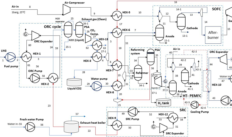
The designated vessel implements an electric propulsion system powered by LNG, as depicted in Figure 1. The innovative system design revolves around the integration of SOFCs to generate primary power, utilizing cold energy derived from LNG to produce valuable electricity. Simultaneously, recognizing the CO2 content in exhaust gas, a CO2 capture system is devised, utilizing the cold energy of LNG.
Furthermore, LNG is introduced into the SOFC before reaching its operational temperature through a regenerative heat exchanger. Notably, a considerable amount of cold energy is lost during LNG gasification. Therefore, this lost energy is utilized by an ORC to enhance the system's power output and aid in cooling the exhaust heat of the CO2 capture system. Additionally, the SRC is employed to absorb waste heat from the SOFC and transfer it to the working fluids. These sequential processes yield electric power through their expander devices.
As per this designation, the targeted vessel stores LNG within an IMO type C tank under conditions of 1.69 bar and -161℃ [29]. In order to utilize LNG in fuel cells, it must undergo regasification, transitioning from a liquid to a gaseous state. However, this phase entails a significant loss of cold energy, which is captured by the ORC before being directed to heat exchangers (HEX-3) and the (HEX-6 and HEX-7) to reach the required temperature for the solid oxide fuel cell (SOFC).
The incorporation of methane reforming involves supplying water to the system. The resulting vaporized water, produced through regeneration (HEX-8), is then directed through stream 30 to the methanol reforming system of the PEMFC and through stream 31 to the SOFC. Air is pressurized to 4 bars from the ambient environment before being delivered to the cathode of the SOFC. Heat exchanger HEX-5 is specifically designed to preheat the supplied air (stream 9) to the optimal operating temperature of the SOFC. Following the electrochemical reaction process within the SOFC stack, the resulting exhaust gas is channeled into an Afterburner for complete combustion.
To optimize the recovery of waste heat, enhance system output power, and utilize the high-temperature exhaust gas effectively, a GT and combined cycles are seamlessly integrated. These elements collaborate harmoniously to reclaim and transform the waste heat energy of exhaust gas into useful energy.
2.2 Simulation Materials
The combined configuration utilizing LNG as the fuel, has been designed and simulated using Aspen HYSYS V12.1 (Aspen Technology Inc., USA). The Aspen Physical Property System is use to analyze the thermal properties of each component within the system [39]. The Peng-Robinson equations has been chosen to assess the thermodynamic conditions of nodes and the compositions and states of points. The main parameter used in this simulation are presented in Table 1.
2.3 Simulation Materials
Fuel utilization factor [19]:
| (1) |
Air utilization:
| (2) |
The required flow rate of fuel and air:
| (3) |
| (4) |
Thus, molar flow of hydrogen supply:
| (5) |
Output of SOFC’s stack [20]:
| (6) |
The current density:
| (7) |
The actual voltage:
| (8) |
where Vloss, VR represents voltage loss (V) and ideal reversible voltage (V), respectively.
| (9) |
where, Vohm represents ohmic losses (V), Vcon is concentration losses (V) and Vact is activation losses (V).
| (10) |
| (11) |
| (12) |
| (13) |
| (14) |
| (15) |
| (16) |
Additionally, the I-V curve is commonly employed for estimating the voltage of the cell stack [21][22]
Electrical efficiency of solid fuel cells:
| (17) |
Or [23]:
| (18) |
where is the LNG’s mass flow rate to the SOFC (kg/h) and LHVLNG is low heating value of LNG (KJ/kg).
System’s performances [22][24]:
Energy efficiency:
| (19) |
where is the net power output of entire system:
| (20) |
LHVLNG as LNG’s lower heating value (kJ/kg).
The exergy efficiency:
| (21) |
3. Results and Discussions
3.1. System Performances
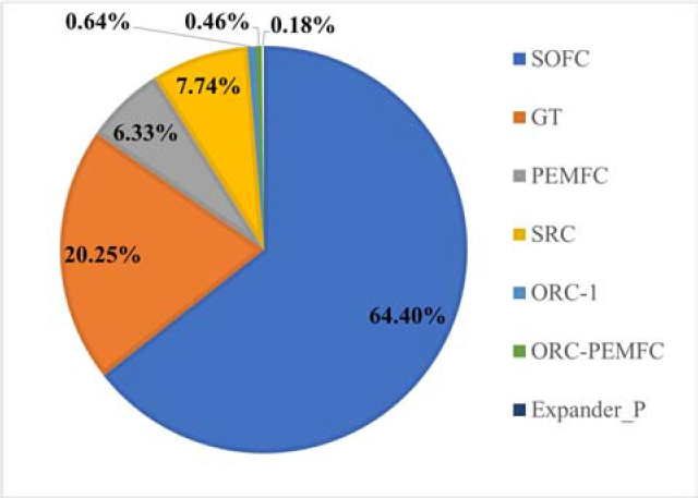
The primary propulsion system of the designated for 3800 kW, while surplus power is required for onboard amenities such as auxiliary equipment, lighting, and crew accommodations. In the baseline simulation scenario, utilizing a cell voltage of 0.739 V and a current density of 1430 A/m², the SOFC achieves an electrical efficiency of 55.47%. Notably, the integrated system demonstrates remarkable performance, yielding a total power output of 5900.42 kW. This configuration incorporates both combined cycles to exploit LNG cold energy and recover exhaust heat. Analysis shows that the power generated by the SOFC contributes to 64.4% of the total output, while the combined cycle-generated power constitutes 35.6%.
By combined the equation (1-21) and simulation results by Aspen Hysys V12.1, the main performance indicators of system are calculated and resulted in Table 2.
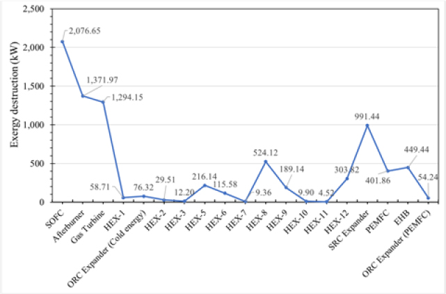
As depicted in Figure 4, the highest magnitude of exergy degradation is attributed to the SOFC, registering at 2,076.65 kW. This outcome is rationalized by the SOFC's role as a significant source of irreversibility within the electrochemical reaction process. Subsequently, the afterburner constitutes the second most prominent contributor to exergy destruction, accounting for 1,371.97 kW. This outcome validates the efficacy of integrating an afterburner within the SOFC system, which ensures thorough fuel and air combustion.
Among the heat exchangers, HEX-8 exhibits the highest exergy degradation at 542.12 kW, a consequence of the temperature differential between two ends, hot and cold sources, inherent to operation of HEX-8. The presence of water in HEX-8, interacting with the SOFC exhaust gas, incurs phase change through vaporization, intensifying exergy destruction in this instance.
In the initial simulation setup, a hydrogen distribution ratio of 1.0 is established, leading to increased exergy loss within the PEMFC compared to scenarios with lower distribution ratios. The direct heat exchange and evaporation processes in the exhaust gas boiler lead to heightened exergy degradation within this component, amounting to 449.44 kW.
3.2 Organic Rankine cycle (ORC)
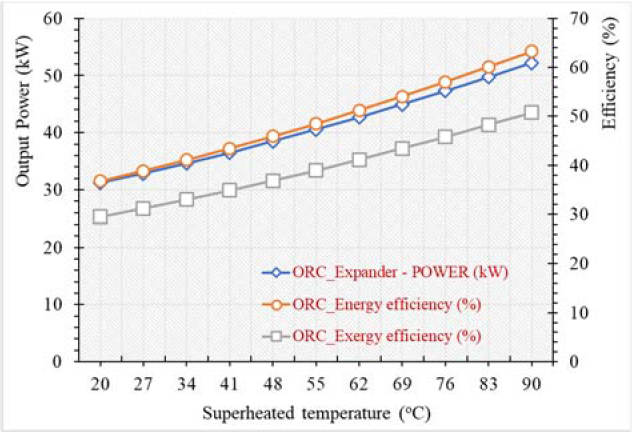
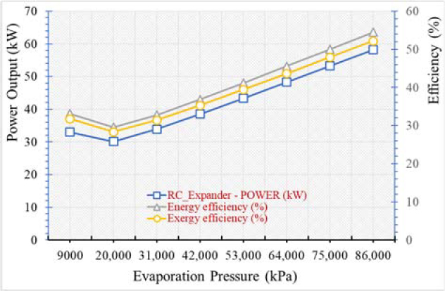
Figures 5 and 6 illustrate the relationship among changes in power output, energy efficiency, and exergy efficiency of the ORC under various superheated temperatures and evaporation pressures of the working fluid.
The efficiency of the cooling energy cycle experiences a proportional increase with the turbine's intake temperature, provided that the evaporation pressure remains constant. Conversely, when maintaining a constant turbine intake temperature, an optimal evaporation pressure, notably identified at 5MPa, emerges to maximize output potential, peaking at 49.74%. This phenomenon is elucidated by the substantial impact of net power production on changes in cooling energy efficiency. Following the determination of the exergy of cold energy from LNG, elevating the turbine inlet temperature effectively mitigates temperature differentials during heat exchange, resulting in significant enhancements in net output power and the efficiency of cold energy exergy.
As the evaporation pressure increases, both heat efficiency and net power production follow a parabolic pattern of change. This behavior arises from the interaction between thermal efficiency, influenced by heat absorption within the cycle, and overall net power production. Notably, when the evaporation pressure reaches 20,000 kPa, there is a risk of water formation at the expander inlet, potentially leading to turbine blade damage under specific conditions. Consequently, this scenario may result in diminished performance and output from the expander and the entire system.
Once the evaporation pressure surpasses 20,000 kPa, the increase in power outstrips the growth in heat absorption within the ORC, leading to an improvement in the cycle's thermal efficiency. Conversely, as heat absorption experiences a more significant rise compared to electricity generation, thermal efficiency declines. Elevated turbine inlet temperatures, while maintaining a constant evaporation pressure, are associated with heightened net power output and increased thermal efficiency. This relationship stems from a notable reduction in the temperature differential during heat transfer as turbine inlet temperatures rise, thereby minimizing energy wastage. This mechanism plays a crucial role in significantly elevating both the thermal efficiency and overall net power production of the system.
3.3 The Impact of the Current Density of the SOFC on the Performance of the System
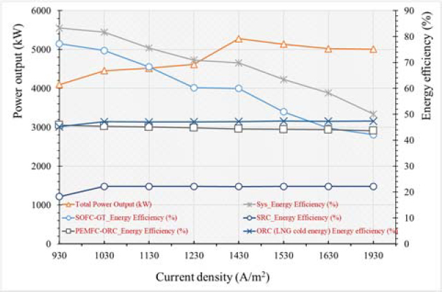
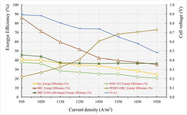
The explored range of current density spans from 930 to 1930 A/m², leading to a corresponding decrease in cell voltage from 0.892 to 0.532 V. However, the power output of the SOFC demonstrates an increase with the augmentation of current density. Within the considered range, the system's power output undergoes a significant enhancement of 1181.94 kW, transitioning from 4096.01 to 5277.95 kW. This phenomenon can be attributed to the rise in exhaust gas temperature and the hydrogen mass flow rate supplied to the SOFC, resulting in increased power generation from 2982.98 kW to the target value of 3800 kW.
Simultaneously, with the increase in current density from 930 to 1930 A/m², the overall energy efficiency of the system decreases from 83.29 to 50.11% (as per equations 19, 21).
Likewise, in the SOFC-GT subsystem, there is a decrease of 35.12% in energy efficiency, dropping from 77.24 to 42.12%, consistent with the previously mentioned pattern in current density. This outcome arises from the need to increase the mass flow rate of LNG within the system to maintain the targeted SOFC power output. This adjustment in fuel supply mass flow rate triggers changes in exhaust gas flow rate and parameters, consequently affecting the enthalpy of the flue gas stream, particularly within and outside regenerative heat exchangers. As a result, the efficiency of waste heat recovery mechanisms is affected, leading to a 3.93% increase in heating cogeneration efficiency within the SRC, rising from 18.23 to 22.16%.
4. Conclusions
The proposed study centers on an integrated system tailored for maritime vessels, combining the synergistic operation of SOFC and PEMFC, leveraging LNG cold energy, and optimizing waste heat recovery. The integration of SOFCs and PEMFCs not only addresses waste heat recovery but also introduces innovations aimed at boosting power generation during critical vessel phases such as start-up and maneuvering, where swift propulsion response is crucial.
Moreover, the incorporation of a CO2 cryogenic capture system, reliant on LNG cold energy, assumes a critical role in purifying discharge gases and ensuring compliance with global emission control regulations. Compared to standalone SOFC systems, the integrated configuration demonstrates significantly enhanced total energy and exergy efficiencies, registering 68.76% and 33.58%, respectively—an impressive 13.29% increase in energy efficiency.
Furthermore, the composite system comprising ORC, GT, SRC, PEMFC-ORC yielded and supplied 2100 kW, constituting 34.96% of the total power provision.
Acknowledgments
This work was supported by the project “Development of guidance for prevention of leaks and mitigation of consequences in hydrogen ships” (Grant No. 20200520) funded by the Ministry of Oceans and Fisheries (Korea). This research was supported by Korea Evaluation Institute of Industrial Technology (KEIT) grant funded by the Korea Government (MOTIE) (RS-2023-00285272).
Author Contributions
Conceptualization, N. Q. Huy; Methodology, N. Q. Huy, T. T. T. Ha; Software, P. A. Duong, T. T. Nam; Formal Analysis, H. K. Kang; Investigation, B. R. Ryu; Resources, T.T.Nam; Data Curation B. R. Ryu; Writing-Original Draft Preparation, T. T. Nam; Writing-Review & Editing, H. K. Kang; Visualization, B. R. Ryu; Supervision, H. K. Kang; Project Administration, B. R. Ryu; Funding Acquisition, H. K. Kang.
References
-
K. Moon, P. Davies, and L. Wright, “Ammonia as a marine fuel : likelihood of ammonia releases,” Journal of Advanced Marine Engineering and Technology, vol. 47, no. 6, pp. 447-454, 2023.
[https://doi.org/10.5916/jamet.2023.47.6.447]

-
H. Xing, C. Stuart, S. Spence, and H. Chen, “Alternative fuel options for low carbon maritime transportation: Pathways to 2050,” Journal of Cleaner Production, vol. 297, p. 126651, 2021.
[https://doi.org/10.1016/j.jclepro.2021.126651]

- Singapore Shipping Association, A Guide for Bunkering Industry - Moving towards IMO 2020 Sulfur Limit, 2020.
- T. I. M. Organization, Resolution MPEC.328(76), IMO, vol. MPEC 76/15, no. 1, pp. 37-72, 2021.
- International Maritime Organzation, Adoption of the Initial IMO Strategy on Reduction of GHG Emissions from Ships, vol. 10, 2023.
-
J. Hansson, S. Brynolf, E. Fridell, and M. Lehtveer, “The potential role of ammonia as marine fuel - Based on energy systems modeling and multi-criteria decision analysis,” Sustainability, vol. 12, no. 8, p. 3265, 2020.
[https://doi.org/10.3390/SU12083265]

-
B. C. Choi and J. I. Lee, “Dynamic simulation of Methane Number variations in LNG fueled vessels with periodic bunkering operations,” Journal of Advanced Marine Engineering and Technology, vol. 46, no. 6, pp. 302-308, 2022.
[https://doi.org/10.5916/jamet.2022.46.6.302]

-
B. R. Ryu, D. P. Anh, Y. H. Lee, and H. K. Kang, “Study on LNG cold energy recovery using combined refrigeration and ORC system: LNG-fueled refrigerated cargo carriers,” Journal of Advanced Marine Engineering and Technology, vol. 45, no. 2, pp. 70-78, 2021.
[https://doi.org/10.5916/jamet.2021.45.2.70]

-
F. Burel, R. Taccani, and N. Zuliani, “Improving sustainability of maritime transport through utilization of Liquefied Natural Gas (LNG) for propulsion,” Energy, vol. 57, pp. 412-420, 2013.
[https://doi.org/10.1016/j.energy.2013.05.002]

-
Q. H. Nguyen, P. A. Duong, B. R. Ryu, and H. Kang, “A study on performances of SOFC integrated system for hydrogen-fueled vessel,” Journal of Advanced Marine Engineering and Technology, vol. 47, no. 3, pp. 120-130, 2023.
[https://doi.org/10.5916/jamet.2023.47.3.120]

-
J. Tan, S. Xie, W. Wu, P. Qin, and T. Ouyang, “Evaluating and optimizing the cold energy efficiency of power generation and wastewater treatment in LNG-fired power plant based on data-driven approach,” Journal of Cleaner Produc-tion, vol. 334, p. 130149, 2022.
[https://doi.org/10.1016/j.jclepro.2021.130149]

-
Y. Liu, J. Han, and H. You, “Exergoeconomic analysis and multi-objective optimization of a CCHP system based on LNG cold energy utilization and flue gas waste heat recovery with CO2 capture,” Energy, vol. 190, p. 116201, 2020.
[https://doi.org/10.1016/j.energy.2019.116201]

- T. H. Lim, R. H. Song, D. R. Shin, J. I. Yang, H. Jung, I. C. Vinke, and S. S. Yang, “Operating characteristics of a 5kW class anode-supported planar SOFC stack for a fuel cell/gas turbine hybrid system,” International Journal of Hydrogen Energy, vol. 33, no. 3, pp. 1076-1083, 2008.
-
J. Pan, M. Li, M. Zhu, R. Li, L. Tang, and J. Bai, “Energy, exergy and economic analysis of different integrated systems for power generation using LNG cold energy and geothermal energy,” Renewable Energy, vol. 202, pp. 1054-1070, 2023.
[https://doi.org/10.1016/j.renene.2022.12.021]

-
P. Li, J. Li, G. Pei, A. Munir, and J. Ji, “A cascade organic Rankine cycle power generation system using hybrid solar energy and liquefied natural gas,” Solar Energy, vol. 127, pp. 136-146, 2016.
[https://doi.org/10.1016/j.solener.2016.01.029]

-
J. Lim, Y. Kim, H. Cho, J. Lee, and J. Kim, “Novel process design for waste energy recovery of LNG power plants for CO2 capture and storage,” Energy Conversion Management, vol. 277, p. 116587, 2023.
[https://doi.org/10.1016/j.enconman.2022.116587]

-
N. Zheng, L. Duan, X. Wang, Z. Lu, and H. Zhang, “Thermodynamic performance analysis of a novel PEMEC-SOFC-based poly-generation system integrated mechanical compression and thermal energy storage,” Energy Conversion Management, vol. 265, p. 115770, 2022.
[https://doi.org/10.1016/j.enconman.2022.115770]

-
Domingues, H. A. Matos, and P. M. Pereira, “Novel integrated system of LNG regasification / electricity generation based on a cascaded two-stage Rankine cycle, with ternary mixtures as working fluids and seawater as hot utility,” Energy, vol. 238, Part C, 2022.
[https://doi.org/10.1016/j.energy.2021.121972]

-
J. Zhou, Z. Wang, M. Han, Z. Sun, and K. Sun, “Optimization of a 30kW SOFC combined heat and power system with different cycles and hydrocarbon fuels,” International Journal of Hydrogen Energy, vol. 47, no. 6, pp. 4109-4119, 2022.
[https://doi.org/10.1016/j.ijhydene.2021.11.049]

-
N. Chitgar and M. Moghimi, “Design and evaluation of a novel multi-generation system based on SOFC-GT for electricity, fresh water and hydrogen production,” Energy, vol. 197, p. 117162, 2020.
[https://doi.org/10.1016/j.energy.2020.117162]

-
Fuerte, R. X. Valenzuela, M. J. Escudero, and L. Daza, “Ammonia as efficient fuel for SOFC,” Journal of Power Sources, vol. 192, no. 1, pp. 170-174, 2009.
[https://doi.org/10.1016/j.jpowsour.2008.11.037]

-
K. H. M. Al-Hamed and I. Dincer, “A novel ammonia solid oxide fuel cell-based powering system with on-board hydrogen production for clean locomotives,” Energy, vol. 220, p. 119771, 2021.
[https://doi.org/10.1016/j.energy.2021.119771]

-
Y. Liu, J. Han, and H. You, “Performance analysis of a CCHP system based on SOFC/GT/CO2 cycle and ORC with LNG cold energy utilization,” International Journal of Hydrogen Energy, vol. 44, no. 56, pp. 29700–29710, 2019.
[https://doi.org/10.1016/j.ijhydene.2019.02.201]

-
E. Gholamian and V. Zare, “A comparative thermodynamic investigation with environmental analysis of SOFC waste heat to power conversion employing Kalina and Organic Rankine Cycles,” Energy Conversion Management, vol. 117, pp. 150-161, 2016.
[https://doi.org/10.1016/j.enconman.2016.03.011]

