Experimental investigation of the entrainment and pressure lifting characteristics of two-phase ejectors
Copyright © The Korean Society of Marine Engineering
This is an Open Access article distributed under the terms of the Creative Commons Attribution Non-Commercial License (http://creativecommons.org/licenses/by-nc/3.0), which permits unrestricted non-commercial use, distribution, and reproduction in any medium, provided the original work is properly cited.
Abstract
An experimental investigation has been conducted to characterize the performance of a two-phase ejector with different mixing tube length ratios. In a two-phase ejector with an optimum mixing tube length, complete mixing between a primary jet and suction flow can occur within the mixing tube. Because geometrical and operating parameters have interconnected effects on ejector performance, the ejector design should be optimized by simultaneously considering these parameters, to achieve higher performance in two-phase ejector application systems. Measurements have been performed in ejectors with five mixing tube length ratios, all with a diffuser area ratio of 3.0. Primary and suction-flow rates at their respective inlets, together with the static pressures at the inlets, have been measured using mass flowmeters and pressure transducers. All tests have been carried out within a Reynolds number ranges of 0.99 × 10⁵ - 2.66 × 10⁵. The results indicate significant improvements in entrainment and pressure-lifting with an increase in the mixing tube to critical length ratio of 16.67. The enhancement in entrainment is due to the increase in traction force, resulting from the enhancement of the mixing between the primary jet and suction flow, whereas the enhancement in pressure lifting is due to the decrease in mixed flow velocity because of the mixing enhancement.
Keywords:
Two-phase ejector, Entrainment, Mixing, Pressure lifting, Ejector application system1. Introduction
The ejector provides a three-fold effect: entrainment, mixing, and pressure lifting. Entrainment, defined as the mass ratio of suction flow rate to primary flow rate, is a direct measure of the mass entrained by the ejector. The pressure-lifting ratio is the ratio of lifted pressure at diffuser outlet to suction inlet pressure. It is a direct means of pressure lifting that the ejector can provide to the entrained stream. Ejectors are preferred for systems with corrosive liquids or other hazardous fluids that are difficult to transfer using conventional pumps and compressors. Within the ejector, a high-pressure primary fluid enters a suction chamber through a nozzle and expands. This primary fluid converts pres-sure energy into velocity. The increased velocity causes reduced pressure, which sucks in and entrains a secondary fluid from the atmosphere or secondary fluid storage facilities. The low-pressure secondary fluid mixes with the high-pressure primary fluid in the suction chamber and mixing tube located downstream of the nozzle. The diffuser section recompresses the mixture stream to an intermediate pressure [1].
The primary objective of research on two-phase ejector appli-cation systems is to improve the performance of the systems. For example, in a refrigeration cycle, a two-phase ejector can be used to entrain and compress vapor at evaporator outlets, resulting in a higher compressor suction pressure and improved cycle performance. Many studies have fo-cused on the effect of primary nozzle design parameters on the performance improvement of application systems [2]. The pa-rameters include the nozzle outlet position [3], primary nozzle throat diameter and angle [4]-[8], and length-to-throat diameter ratio [9][10]. The parameters were the primary nozzle throat di-ameter and angle, length-to-throat diameter ratio, and nozzle out-let position. Although the efficiency of the two-phase ejector plays a pivotal role in enhancing the performance of ejector appli-cation systems, it is often overlooked in favor of other factors. Opletal et al. [11] have developed a method for designing an upflow ejector loop reactor for coalescent systems with respect to the different energy dissipations and mechanisms of interfacial mass transfer in the ejector. Measurements and correlations of the gas entrainment rate and oxygen volumetric mass transfer coeffi-cient have been reported to describe their dependence on operat-ing conditions, for various geometries of the ejector. Im and Song [12] have conducted analytical and experimental investiga-tions to characterize the performance of a short ejector. They suggest a new analytical model for a short ejector, with the mix-ing tube length set based on control volume analysis and jet ex-pansion model. Akagi et al. [13] have investigated the pressure-lifting characteristics of a two-phase ejector for application in a carbon dioxide heat pump cycle. The geometric parameters are the diameter and length of the constant-area mixing tube and primary nozzle position. Park and Yang [14]-[16] have experi-mentally investigated the flow and mass transfer characteristics of vertical and horizontal aeration processes with the design parame-ters of an orifice or annular ejector.
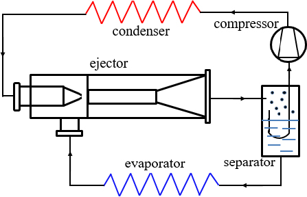
A two-phase ejector can be used as an alternative device for advanced refrigeration technologies because of its capability in recovering the expansion energy that is generally lost during isenthalpic expansion in conventional vapor-compression refrig-eration cycles. Expansion work recovery is a means of improving overall cycle performance [17]. A two-phase ejector uses the expansion of a high-pressure primary liquid to entrain low-pressure suction vapor and increase its pressure, as shown in Figure 1. Figure 1 shows a schematic cycle layout of an ad-vanced two-phase ejector refrigeration system. In a refrigeration system, a two-phase ejector can be used to entrain and compress vapor at the evaporator outlet, resulting in higher compressor suction pressure and reduced compressor input power. In this system, entrainment and pressure-lifting characteristics are the key performance metrics of two-phase ejectors. Although our understanding of each performance parameter in ejector applica-tion systems has been steadily advancing, simultaneously inves-tigating the performance parameters is desirable. However, to the best of our knowledge, only a few studies have explored the two-phase ejector itself to simultaneously investigate the entrainment and pressure-lifting characteristics with the design parameters [2][4].
The performance of two-phase ejectors must be sufficiently high for a sufficiently broad range of conditions to justify their use and associated costs. However, the traction force for the entrainment of the suction fluid and static pressure within the two-phase ejector vary with the mixing tube length, and the pres-sure-lifting behavior differ according to the entrainment ratio and diffuser design. Simultaneously describe performance parameters, as well as understanding the quantification of the ejector perfor-mance is significant. Therefore, the objective of this study is to experimentally investigate the entrainment ratio (MR) and pres-sure lifting ratio (PLR) inside a two-phase ejector simultaneously with mixing tube length ratios (LRm) of 5.0, 7.67, 12.67, 16.67 and 19.67, within a Reynolds number range of 0.99 × 10⁵ - 2.66 × 10⁵.
Generally, an optimum mixing tube length provides the maxi-mum entrainment rate for the suction fluid in a two-phase ejector. A lower length can cause inefficient mixing of the two streams, leading to a decrease in the traction force of the suction flow. However, a higher length can result in a considerable friction loss, leading to a negative impact on the pressure lifting. Therefore, an optimization procedure for proper ejector design is crucial for application purposes.
2. Experimental Setup and Methods
2.1 Central Nozzle Ejector
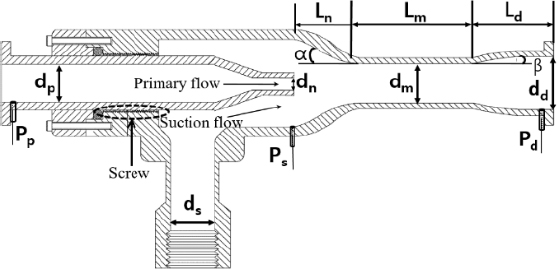
A two-phase ejector is a type of gas-liquid contactor that di-rectly transfers energy and momentum from a high-energy prima-ry fluid to a low-energy suction fluid, and mixes the two fluids. Figure 2 shows an experimental ejector model along with its main internal parts and geometrical dimensions. The ejector was designed to offer flexibility for design parameter variation in the experimental ranges. The ejector was of the central nozzle type, characterized by a primary jet line positioned at the center, with the suction flow line located on the outside. The ejector had a suction chamber, parallel mixing tube, and conical diffuser, all featuring circular cross sections. Table 1 summarizes the detailed geometric specifications of the ejector. A round-edge orifice-type primary nozzle with an outlet diameter of 8 mm was used, result-ing in a primary nozzle area ratio (ARn) of 0.28 (Equation (1)). In Equation (1) ARn is defined as the area ratio of the primary nozzle outlet to the mixing tube. The semi-cone angle of the suc-tion chamber (α) was 46.4°. The mixing tube-to-primary nozzle tip spacing (Ln) was 13 mm, resulting in a primary nozzle dis-tance ratio (LRn) of 0.87, as calculated by Equation (2) [18]. The mixing tube length was varied from 75 mm to 295 mm, re-sulting in mixing tube length ratios (LRm) of 5.0, 7.67, 12.67, 16.67, and 19.67. The LRm values were determined by dividing the mixing tube length by its diameter, as defined in Equation (3). A conical diffuser with an outlet diameter of 26 mm yielding an area ratio (ARd) of 3.0, was employed. The ARd ratio was is calculated using Equation (4) as the ratio of the diffuser outlet area to the mixing tube area. The length of the diverging section of the diffuser (Ld) was 100 mm, resulting in a diffuser semi-cone angle (β) of approximately 3.15°. Table 2 lists the mixing tube lengths and diffuser outlet area ratios, which are the experi-mental parameters used in this study. An O-seal was used to prevent leakage between the fixed and movable pieces of the ejector. In addition, three pressure taps were installed on the ejec-tor walls at the primary flow inlet, primary nozzle outlet, and diffuser outlet. The primary nozzle area, primary nozzle distance, mixing tube length, and diffuser outlet area ratios are defined as follows.
| (1) |
| (2) |
| (3) |
| (4) |
2.2 Experimental Setup
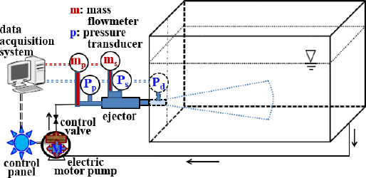
The experimental apparatus with a central nozzle ejector was designed to operate as a closed circulation loop, as shown in Figure 3. It consisted of an electric motor-pump, central nozzle ejector assembly, circulation water tank, and measurement or control accessories (i.e. data acquisition system, water and air flow meters, pressure and vacuum transducer, control valve and panel). The primary flow was supplied through the circulation water tank by a 7.5 kW induction motor with a vertical multistage pump. All experiments were conducted in a rectangular tank of 1.66 m length, 0.46 m width, and 0.8 m height. The water tank was composed of transparent acrylic. The ejector diffuser outlet was placed on the shorter plane side wall such that its axis lied horizontally 0.2 m above the bottom and at the middle of the side wall.
2.3 Experimental Method
In the two-phase jet experiments [18], the tank was filled with clean tap water circulated through the central nozzle ejector using an electric motor -pump. The primary water jet from the nozzle was controlled by varying the speed of the motor -pump from 500 to 1,400 rpm in increments of 100 rpm, as shown in Table 2. With the speed variation, the pressure at the primary water inlet was varied from 2.17 to 10.6 bar (all pressures quoted are abso-lute). Suction air was entrained from the atmosphere and the mixed flow was discharged into the circulation water tank. The volumetric primary water flow rate Qp supplied by the motor -pump was regulated by rpm control and measured using an elec-tromagnetic flowmeter (Kometer, KTM-800) at the primary noz-zle inlet. The volumetric suction air-flow rate, Qs, was measured using a thermal digital mass flowmeter (MKP, TSM-D240) at the suction chamber inlet. The accuracies of the flow measurement were within ±0.5 and ±1.0 % of the full scale for primary water and suction air, respectively. All experiments were carried out with tap water and air at 21±1 and 24±1 ℃, respectively.
The Reynolds number Re=dnun/νp was calculated based on the primary nozzle outlet diameter and the averaged cross-sectional flow velocity at the nozzle outlet, where νp is the kinematic vis-cosity of the primary fluid (tap water). The cross-sectional flow velocity was the ratio of the volume of the primary flow rate (Qp) to the area of the primary nozzle outlet (An) [19].
The entrainment or mass ratio (MR) is defined as the ratio of the suction flow rate to the primary flow rate, as expressed in Equation (5).
| (5) |
where γ and φ are the density and volumetric flow ratios, respec-tively, for the suction air to the primary water. The mass ratio measures the capacity of the ejector to draw suction fluid.
Static pressures at the inlet and outlet of the primary nozzle (Pp, Pn) and the diffuser outlet (Pd) were measured using a 5-channel digital data logger (HANYOUNG NUX, GR200) with digital pressure transducers (WIKA, A-10) with an accuracy of 0.5% of the full scale. By substituting Pn for Ps (pressure in the suction chamber, PSC), the pressure drop in the primary nozzle (PDN) and pressure lift in the diffuser (PLD) were calculated using Equations (6) and (7), respectively. With PSC and PLD, the pressure lifting ratio (PLR) is defined by Equation (8).
| (6) |
| (7) |
| (8) |
Based on the measurement results of the static pressures, the ejector efficiency is given as [20][21]
| (9) |
where the numerator is the ejector output for the compression of the suction fluid, and the denominator is the energy input rate of the primary stream, as defined by [20].
To calculate the discharge coefficient Cd, assuming that the po-tential energy between the primary nozzle inlet and outlet is neg-ligible and that the density of the primary fluid is constant and independent of pressure, Bernoulli’s equation is given as [22]
| (10) |
For the actual primary fluid (tap water), by introducing a dis-charge coefficient, Equation (10) can be rearranged and rewrit-ten as
| (11) |
where δ is the diameter ratio of the primary nozzle outlet to the primary flow inlet. The PDN across the primary nozzle, which is the pressure drop that occurs as the fluid is discharged from the nozzle outlet to the suction chamber, varies according to the noz-zle design, suction chamber environment, fluid type, and friction losses. The discharge coefficient for each test run was determined from experimental data using the design parameters.
Experimental uncertainty analysis was performed following the NIST guidelines [4][23]. Uncertainties in the measured data for the flow rate and pressure were checked separately. The esti-mated uncertainties of MR and PLR were determined based on the primary and suction flow rates and pressure data and have values of 2.32 and 14.67%, respectively, with a 95% confidence level. The test matrix used in this study was organized as fol-lows. For one primary flow nozzle, five parallel mixing tubes of varying LRm for an ARd of 3.0, were tested to investigate the characteristics of MR and PLR. From each test run, the primary and suction flow rates at the primary nozzle and suction inlets, and static pressure data at three locations along the ejector were obtained.
3. Results and Discussions
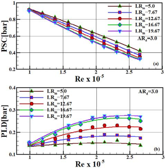
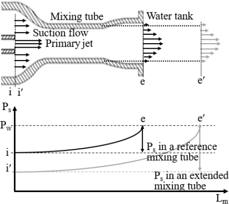
Figure 4 shows the pressure in the suction chamber PSC and pressure lift in the diffuser PLD as functions of Re obtained for the mixing tube length ratio LRm at a diffuser outlet area ratio ARd of 3.0. The calculated Reynolds numbers based on the pri-mary nozzle outlet velocity and nozzle exit diameter ranged from 0.99 × 10⁵ to 2.66 × 10⁵, as shown in Table 2. The range of Re values expected to be more efficient for the mixing and mass transfer processes was consistent with the results of Lima Neto et al. [24]. The absolute PSC decreased linearly with increasing Re owing to the enhancement in the suction vacuum pressure. This enhancement resulted from an increase in the primary flow velocity at the nozzle exit. As the mixing tube LRm increased, the PSC reduced, owing to the enhancement in the suction vacuum pres-sure. Figure 5 illustrates the enhancement mechanism of the suction vacuum pressure.
As the mixing tube lengthened, more mixing or a higher in-crease in static pressure occurred within the mixing tube. How-ever, the diffuser outlet pressure remained constant at the same pressure as that of the water tank. Therefore, the static pressure Ps at the suction inlet with a longer mixing tube must decrease, leading to an increase in the suction vacuum pressure, as demon-strated by Im and Song [12]. With increasing LRm, the reduction rate of the PSC decreased, resulting in a nearly constant value. However, with increasing Re, the absolute PLD increased be-cause of the enhancement in momentum transfer from the higher-pressure primary jet to the lower-pressure suction flow. As the mixing tube lengthened, the PLD increased owing to the mixing enhancement as well as the enhancement in the momentum trans-fer between the two streams. However, with a longer mixing tube length and higher Re, the rate of increase of the PLD reduced, because of the increase in pressure drop resulting from the fric-tional loss in the mixing tube wall.
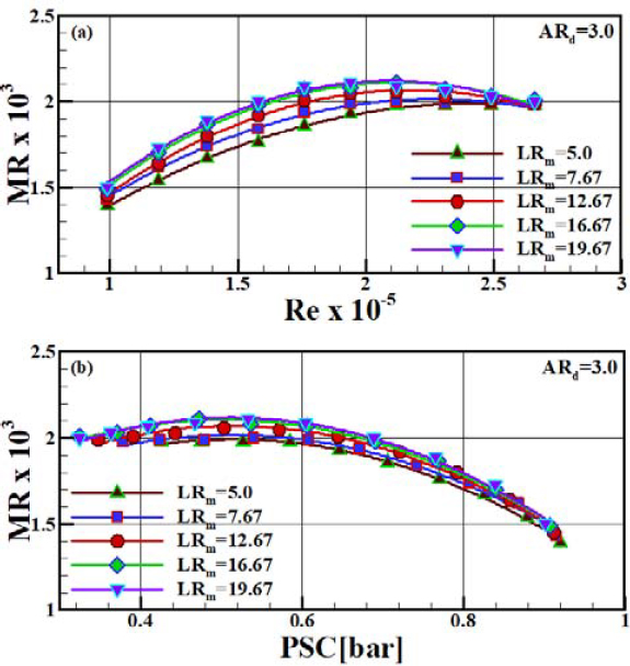
The length of the parallel mixing tube played an important role in creating a uniform velocity profile at the diffuser inlet of the two-phase ejector. The uniform velocity was due to the momen-tum transfer from the high-pressure primary jet to the low-pressure suction flow and the mixing enhancement between the two streams. Uniformity of velocity was essential to increase the entrainment of the suction fluid and decrease the induced losses in the diffuser, and consequently, for efficient pressure lifting. Figure 6 plots the effect of the mixing tube length on MR as a function of Re or PSC for ARd 3.0. The MR increased with in-creasing Re and then decreased slightly. This variation occurred because as Re increased, the incompressible primary water flow rate increased monotonically and, the compressible suction air flow rate increased; however, the increasing rate of the compress-ible suction air flow reduced. Although the suction vacuum pres-sure increased or PSC decreased linearly with increasing Re, as shown in Figure 4, the rate of increase of the compressible suc-tion air flow reduced at a relatively higher value of Re because the resistance of the suction air flow was enhanced, owing to the compressibility effect [14][15]. In addition, the reduction in the rate of increase of the suction air flow was attributed to the re-duced suction chamber area owing to the expanding primary liquid jet at a relatively higher Re [11]. As LRm increased, the entrainment performance was enhanced up to an LRm of 16.67 and then remained nearly constant. This entrainment enhancement was due to an increase in the traction force or suction vacuum pressure as described in Figure 4 and illustrated in Figure 5. The increase in the traction force for the suction flow may be due to the mixing enhancement between the two streams within the mixing tube and the discharge of the uniform mixed flow from the mixing tube outlet, resulting from an increase in the interaction length, and consequently the surface for momentum transfer. Mixing enhancement and a uniform discharge flow may lead to an enhanced traction force on the suction fluid. On the other hand, for shorter length ratios, the lower entrainment char-acteristics may be ascribed to the fact that non-uniform mixed flow in which the core of the primary jet still exists is discharged from the mixing tube outlet owing to partial mixing, thus leading to reduced traction force for the suction flow. The variation in the MR with PSC differ from that in the MR with Re because of the inverse relationship between Re and PSC, as shown in Figure 4. MR has a maximum value at approximately Re = 2.12 × 10⁵ or PSC = 0.5 bar for an LRm of 16.67.
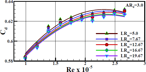
To confirm the variation in MR with LRm, the discharge coef-ficient Cd was calculated using Equation (11). Figure 7 shows the variation of Cd as a function of Re with the mixing tube length ratio LRm as a parameter. With the lengthening of the mix-ing tube up to an LRm of 16.67 the discharge coefficient decreas-es whereas further lengthening of the mixing tube has little effect on Cd. The decrease in Cd may be due to the fluid dynamic inter-action between the entrained suction flow and the flow area oc-cupied by the primary jet inside the two-phase ejector. This is because with increasing MR, the actual area available for the primary jet decreases owing to the increase in the suction air-flow [25]. In addition, the reduction in Cd with lengthening of the mixing tube up to an LRm of 16.67 is due to the increase in PDN, as can be seen from Equation (11). This reduction of Cd is opposite to the enhancement of MR with lengthening of the mixing tube up to an LRm of 16.67, owing to the decrease in PSC. Both the increase in PDN and the decrease in PSC were caused by the increase in the suction vacuum pressure, as can be deduced from Equation (6) and the variation in PSC shown in Figure 4. Therefore, it was confirmed that owing to the increases in the suction vacuum pressure, Cd reduced and MR increased up to an LRm of 16.67. In addition, it was found that at a constant Re, the variation in Cd with LRm is dependent only on PDN because the other parameters of Equation (11) have constant values. As Re increased, Cd first increased linearly and then decreased slightly. The result is due to the fact that as Re rises, Qp and PDN increase linearly; however as shown in Equation (11), the denominator is proportional to the square root of PDN.
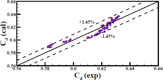
To develop a correlation model for Cd as a function of Re and LRm, a linear regression method was used, and the result is given by Equation (12). The result is in agreement with the experi-mental data within ±0.78% average deviation and ±1.45% maxi-mum deviation, as illustrated in Figure 8. The model exhibited a correlation coefficient (R2) of 0.946 and standard error of esti-mate of 0.0035. Based on this correlation, it was observed that Re had a greater effect on Cd than does LRm.
| (12) |
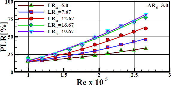
In ejectors, the suction flow is entrained by the static pressure difference between the atmosphere and suction chamber. As the momentum transfer from the primary jet to the suction flow progressed, the static pressure increased along the parallel mixing tube. As the length of the mixing tube increased, a greater pressure increase occurred in the mixing tube because of the enhanced momentum transfer between the two streams. In an ideal case, the mixing tube should be sufficiently long to transfer the momentum completely and homogenize the two phases. A shorter length leads to a partial momentum transfer, whereas an excessive length leads to an additional pressure drop owing to wall friction. Figure 9 shows the effect of the mixing tube length on the PLR as a function of Re for an ARd of 3.0. The PLR was enhanced by increasing Re and LRm. The enhancement of PLR by Re occurs because as Re increases, PLD increases and PSC decreases, as shown in Figure 4. It was found that up to an LRm of 16.67, the lengthening effect of the mixing tube on the PLR increased, whereas beyond LRm, the effect decreased. The in-crease in PLR with the lengthening of the mixing tube up to an LRm of 16.67 is due to the increase in PLD. The increase in the PLD resulted from the reduced mixing tube outlet velocity of the mixture flow owing to the mixing enhancement between the two phases. Further lengthening of the mixing tube has a negative effect on the PLR because of the additional pressure drop result-ing from frictional resistance, thus leading to a decrease in the rate of increasing of the PLR.
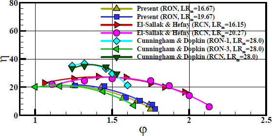
Figure 10 shows the comparison of ejector efficiencies as a function of volume flow ratio (φ) for different primary nozzles and mixing tube length ratios. The ejector efficiencies of the present study with a round-edged orifice nozzle (RON) were compared with the results of Cunningham and Dopkin [20] and El-Sallak and Hefny [21]. The results of Cunningham and Dop-kin were for round-edged orifice and round-edged converging nozzles (RONs and RCNs) with an LRm of 28, whereas those of El-Sallak and Hefny were for a RCN with two different LRms of 16.15 and 20.27. The efficiencies of the present study are under estimated compared with the RON-1 and RCN results of Cun-ningham and Dopkin, and those of El-Sallak and Hefny. Howev-er, the present result are in good agreement with the RON-3 re-sults of Cunningham and Dopkin within the volume-flow ratio range of this study. The under estimated results in this study can be attributed to the primary nozzle design and operating condition [21][26]. It was found that the reported difference between RON-1 and RON-3 of Cunningham and Dopkin RCN was only the nozzle throat length, but the difference in efficiency was ap-proximately 50% for the same volume-flow ratio.
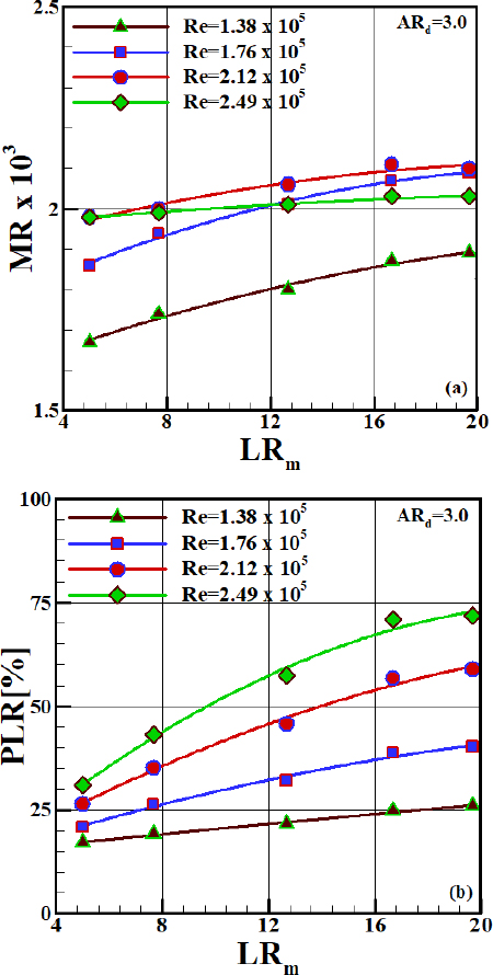
To achieve higher performance for a two-phase ejector applica-tion system, the MR and PLR should also be high. However, there is a trade-off between the MR and PLR therefore, the ejec-tor design should be optimized by considering these parameters simultaneously. Figure 11 shows the plots for the effect of the mixing tube length ratio on the MR and PLR at an ARd of 3.0 for different Reynolds numbers. The increase in Re results in MR enhancement to its maximum value, which occurs at Re of 2.12 × 10⁵, and then decreases; whereas, as Re increases, the PLR in-creases for all ranges of Re. It is apparent that the MR is less sensitive to LRm at higher Re and is independent of LRm beyond a critical LRm, whereas the PLR increases linearly up to the criti-cal LRm, and the increasing rate of the PLR decreases beyond the critical LRm for all ranges of Re. It is concluded that in the LRm and Re ranges of this research, MR has a maximum value of approximately 0.002 for the critical LRm of 16.67 at approximately Re = 2.12 × 10⁵. It was also found that up to an LRm of 16.67, the momentum-transfer effect between the two streams with the lengthening of the mixing tube was predominant and overcame the pressure drop resulting from the friction loss within the mixing tube, thus leading to a linear increase in the PLR.
4. Conclusion
Experimental investigations were conducted to characterize the entrainment and pressure-lifting characteristics of a two-phase ejector with mixing tube length ratios. The following conclusions were drawn based on the results of this investigation:
- 1. The correlation result of Cd as a function of Re and LRm is in agreement with the experimental data within 0.78% av-erage deviation, and Re has more effect on Cd than does LRm.
- 2. The MR exhibited a maximum value of approximately 0.002 for a length ratio LRm of 16.67 at approximately Re = 2.12 × 10⁵. In addition, up to the length ratio, PLR linearly increased with increasing Re, because the momentum trans-fer effect between the higher pressure primary jet and lower pressure suction flow is predominant, and overcomes the pressure drop resulting from friction loss.
- 3. The entrainment enhancement with an increasing mixing tube to the length ratio of 16.67 is due to the increase in the traction force resulting from mixing enhancement between the two streams, whereas the pressure lifting enhancement is due to the decrease in the mixed flow velocity discharged from the mixing tube outlet because of the mixing en-hancement.
Nomenclature
| A : | area [mm2] |
| AR : | area ratio |
| Cd : | discharge coefficient |
| d : | diameter [mm] |
| L : | length [mm] |
| LR : | length ratio |
| MR : | entrainment or mass ratio |
| P : | pressure [bar] |
| PDN : | pressure drop in primary nozzle [bar] |
| PLD : | pressure lift in diffuser [bar] |
| PLR : | pressure lifting ratio [%] |
| PSC : | pressure in suction chamber [bar] |
| Q : | volume flow rate [m3/s] |
| Re : | Reynolds number |
| u : | velocity [m/s] |
Greek letters
| α : | suction chamber semi-cone angle [°] |
| β : | diffuser semi-cone angle [°] |
| δ : | diameter ratio of primary nozzle outlet to inlet |
| η : | ejector efficiency [%] |
| φ : | volume flow rate ratio of suction air to primary water |
| ρ : | density [kg/m3] |
| γ : | density ratio of suction air to primary water |
| ν : | kinematic viscosity [m2/s] |
Subscripts
| c : | suction chamber |
| d : | diffuser |
| m : | mixing tube |
| n : | primary nozzle |
| p : | primary flow inlet or primary fluid |
| s : | suction flow inlet or suction fluid |
Acknowledgments
This research was supported by the Basic Science Research Program through the National Research Foundation of Korea (NRF), funded by the Ministry of Education (NRF-2019R111A3A01057227).
Author Contributions
Conceptualization, S. K. Park and H. C. Yang; Methodology, S. K. Park and H. C. Yang; Software, S. K. Park and H. C. Yang; Formal Analysis, S. K. Park and H. C. Yang; Investigation, S. K. Park and H. C. Yang; Resources, S. K. Park and H. C. Yang; Data Curation S. K. Park and H. C. Yang; Writing-Original Draft Preparation, S. K. Park and H. C. Yang; Writing-Review & Editing, S. K. Park and H. C. Yang; Visualization, H. C. Yang; Supervision, H. C. Yang; Project Administration, H. C. Yang; Funding Acquisition, H. C. Yang.
References
-
G. Besagni, “Ejectors on the cutting edge: The past, the present and the perspective,” Energy, vol. 170, pp. 998-1003, 2019.
[https://doi.org/10.1016/j.energy.2018.12.214]

- N. Lawrence and S. Elbel, “Analysis and comparison of two-phase ejector performance metrics for R134a and CO2 ejectors,” 15th International Refrigeration and Air Conditioning Conference, Purdue, Illinois, USA, p. 2188, 2014.
-
K. Ameur and Z. Aidoun, “Nozzle displacement effect on two-phase ejector performance: An experimental study,” Journal of Applied Fluid Mechanics, vol. 11, no. 4, pp. 817-823, 2018.
[https://doi.org/10.29252/jafm.11.04.28385]

-
Y. Jeon, J. Jung, D. Kim, S. Kim, and Y. Kim, “Effects of ejector geometries on performance of ejector-expansion R410A air conditioner considering cooling seasonal performance factor,” Applied Energy, vol. 205, pp. 761-768, 2017.
[https://doi.org/10.1016/j.apenergy.2017.08.059]

-
N. B. Sag and H. K. Ersoy, “Experimental investigation on motive nozzle throat diameter for an ejector expansion refrigeration system,” Energy Conversion Management, vol. 124, pp. 1-12, 2016.
[https://doi.org/10.1016/j.enconman.2016.07.003]

-
K. Banasiak, A. Hafner, and T. Andresen, “Experimental and numerical investigation of the influence of the two-phase ejector geometry on the performance of the R744 heat pump,” International Journal of Refrigeration, vol. 35, no. 6, pp. 1617-1625, 2012.
[https://doi.org/10.1016/j.ijrefrig.2012.04.012]

-
H. Zare-Behtash, N. Gongora-Orozco, and K. Kontis, “Effect of primary jet geometry on ejector performance: A cold-flow investigation,” International Journal of Heat and Fluid Flow, vol. 32, no. 3, pp. 596-607, 2011.
[https://doi.org/10.1016/j.ijheatfluidflow.2011.02.013]

-
S. Elbel and P. Hrnjak, “Experimental validation of a prototype ejector designed to reduce throttling losses encountered in transcritical R744 system operation,” International Journal of Refrigeration, vol. 31, no. 3, pp. 411-422, 2008.
[https://doi.org/10.1016/j.ijrefrig.2007.07.013]

-
F. Liu and E. A. Groll, “Study of ejector efficiencies in refrigeration cycles,” Applied Thermal Engineering, vol. 52, no. 2, pp. 360-370, 2013.
[https://doi.org/10.1016/j.applthermaleng.2012.12.001]

-
C. Lin, W. Cai, Y. Li, J. Yan, and Y. Hu, “The characteristics of pressure recovery in an adjustable ejector multi-evaporator refrigeration system,” Energy, vol. 46, no. 1, pp. 148-155, 2012.
[https://doi.org/10.1016/j.energy.2012.09.007]

-
M. Opletal, P. Novotny, V. Linek, T. Moucha, and M. Kordac, “Gas suction and mass transfer in gas-liquid up-flow ejector loop reacator. Effect of nozzle and ejector geometry,” Chemical Engineering Journal, vol. 353, pp. 436-452, 2018.
[https://doi.org/10.1016/j.cej.2018.07.079]

-
J. H. Im and S. J. Song, “Mixing and entrainment characteristics in circular short ejectors,” Journal of Fluids Engineering, vol. 137, no. 5, 2015.
[https://doi.org/10.1115/1.4029412]

- S. Akagi, C. Dang, and E, Hihara, “Characteristics of pressure recovery in two-phase ejector applied to carbon dioxide heat pump cycle,” 9th International IEA Heat Pump Conference, Zurich, Switzerland, pp. 1-8, 2008.
-
S. K. Park and H. C. Yang, “An experimental investigation of the flow and mass transfer behavior in a vertical aeration process with orifice ejector,” Energy, vol. 160, pp. 954-964, 2018.
[https://doi.org/10.1016/j.energy.2018.07.064]

-
S. K. Park and H. C. Yang, “Experimental investigation on mixed jet and mass transfer characteristics of horizontal aeration process,” International Journal of Heat and Mass Transfer, vol. 113, pp. 544-555, 2017.
[https://doi.org/10.1016/j.ijheatmasstransfer.2017.05.120]

-
S. K. Park and H. C. Yang, “Flow and oxygen-transfer characteristics in an aeration system using an annular nozzle ejector,” Industrial and Engineering Chemistry Research, vol. 52, no. 4, pp. 1756-1763, 2013.
[https://doi.org/10.1021/ie302208e]

-
M. Yazdani, A. A. Alahyari, and T. D. Radcliff, “Numerical modeling of two-phase supersonic ejectors for workrecovery applications,” International Journal of Heat and Mass Transfer, vol. 55, no. 21-22, pp. 5744-5753, 2012.
[https://doi.org/10.1016/j.ijheatmasstransfer.2012.05.071]

-
H. C. Yang, “Effect of primary nozzle area and distance ratios of ejector on flow characteristics in water treatment process,” Transactions of the Korean Society of Mechanical Engineers B, vol. 42, no. 12, pp. 777-785, 2018 (in Korean).
[https://doi.org/10.3795/KSME-B.2018.42.12.777]

-
H. Yadav, A. Agrawal, and A. Srivastava, “Mixing and entrainment characteristics of a pulse jet,” International Journal of Heat and Fluid Flow, vol. 61, pp. 749-761, 2016.
[https://doi.org/10.1016/j.ijheatfluidflow.2016.08.006]

-
R. G. Cunningham and R. J. Dopkin, “Jet breakup and mixing throat lengths for liquid jet gas pump,” Journal of Fluids Engineering, vol. 96, no. 3, pp. 216-226, 1974.
[https://doi.org/10.1115/1.3447144]

-
M. El-Sallak and M. M. Hefny, “Experimental investigation of the performance of liquid gas jet pumps with inlet swirling,” Proceedings of the Institution of Mechanical Engineers, Part A, vol. 224, no. 3, pp. 363-372, 2010.
[https://doi.org/10.1243/09576509JPE801]

-
F. Rahman, D. B. Umesh, D. Subbarao, and M. Ramasamy, “Enhancement of entrainment rates in liquid-gas ejectors,” Chemical Engineering and Processing: Process Intensification, vol. 49, no. 10, pp. 1128-1135, 2010.
[https://doi.org/10.1016/j.cep.2010.08.014]

-
B. N. Taylor and C. E. Kuyatt, Guidelines for Evaluating and Expressing the Uncertainty of NIST Measurement Results, NIST Technical Note 1297, 1994.
[https://doi.org/10.6028/NIST.TN.1297]

-
I. E. Lima Neto, D. Z. Zhu and N. Rajaratnam, “Horizontal injection of gas-liquid mixtures in a tank,” Journal of Hydraulic Engineering, vol. 134, no. 12, pp. 1722-1731, 2008.
[https://doi.org/10.1061/(ASCE)0733-9429(2008)134:12(1722)]

-
F. A. Hammad, K. Sun, J. Jedelsky, and T. Wang, “The effect of geometrical, operational, mixing methods, and rheological parameters on discharge coefficients of internalmixing twin-fluid atomizers,” Processes, vol. 8, no. 5, p. 563, 2020.
[https://doi.org/10.3390/pr8050563]

-
P. Havelka, V. Linek, J. Sinkule, J. Zahradnik, and M. Fialova, “Effect of the ejector configuration on the gas suction rate and gas hold-up in ejector loop reactors,” Chemical Engineering Science, vol. 52, no. 11, pp. 1701-1713, 1997.
[https://doi.org/10.1016/S0009-2509(97)00003-1]


