Separation characteristics of prepared exhalation gases scattered in water using hollow fibers
Copyright © The Korean Society of Marine Engineering
This is an Open Access article distributed under the terms of the Creative Commons Attribution Non-Commercial License (http://creativecommons.org/licenses/by-nc/3.0), which permits unrestricted non-commercial use, distribution, and reproduction in any medium, provided the original work is properly cited.
Abstract
Underwater breathing requires a large amount of oxygen. As water contains limited dissolved oxygen, devices must be sufficiently large to obtain the required oxygen. Exhaled breath, which contains a large amount of oxygen, can be reused to make devices compact and portable. In this work, gases with the characteristics of exhaled breath were mixed with water using a hollow fiber membrane. The gases were mixed with water in the form of small bubbles, which increased the contact area between the gases and water. The mixed state was visualized by increasing the amount of prepared gases. Dissolved gases were separated from water containing the prepared gases. The amount of separated gases increased with the amounts of prepared gases and water. The separated dissolved gases could be used for underwater respiration.
Keywords:
Hollow fibers, Exhalation, Scattering, Prepared exhalation gases, Separation1. Introduction
Dissolved oxygen in water can be used for respiration. Certain insects breathe underwater using numerous hairs on their surfaces [1]. The mechanism of how the insects that live in air can breathe underwater is as follows: Necessary oxygen is obtained underwater using a plastron. The insects that live in air can receive the oxygen required for breathing by creating an air layer underwater if they have their hair on the surface. The interface between the air layer and water depends on the hair diameter, spacing, contact angle, and water depth. These parameters can be mathematically modeled to determine the water depth at which the air–liquid boundary layer does not collapse. The contact area of the gas–liquid interface increases with the water depth. Even if a hairy insect falls into water, it can survive by breathing underwater using the plastron for a certain duration.
An experiment performed using an empty box fabricated from a membrane material has shown that bees can breathe underwater for 60 h [2]. A model has been presented to analyze the transport characteristics of dissolved oxygen in water. When a hollow boxshaped membrane is present in water, the amount of transported oxygen varies depending on the characteristics of the membrane. If the oxygen inside a box fabricated from a material that does not transport oxygen is consumed by a battery, the oxygen content decreases with the battery capacity. If an experiment is performed using an empty box created from a membrane material that allows oxygen to permeate, the oxygen content initially decreases and then gradually becomes constant. In other words, the oxygen inside the box is consumed by the battery and the oxygen in the water is transported inside the box because of the difference in the oxygen partial pressure. Therefore, the oxygen content inside the box becomes constant. The contents of transported and constant oxygen depend on the membrane material, shape, and thickness. The influence of these parameters is modeled using mathematical formulas, and the effectiveness of the model is demonstrated through experiments. As human breathing can be compared to the consumption of oxygen by a battery in an empty box, breathing is possible underwater without additional power by adjusting the contact area with water. However, as humans consume more oxygen than batteries used in experiments, an empty box with a large contact area is required.
The separation rate of dissolved oxygen has been improved by coating with magnetic materials. When electricity is supplied, they become magnetized; therefore, the amount of separated oxygen can be controlled [3].
Power-free devices have the advantage of minimizing energy consumption; however, the amount of captured oxygen is limited by the material structure, shape, and contact area. A large contact area is required to obtain a large amount of oxygen; however, this increases the volume. As water is not rich in dissolved oxygen, a large-capacity device is required for humans to use it underwater.
A method that uses power is effective for capturing a large amount of underwater oxygen for human breathing. The diameter of hollow fibers is similar to that of hair, and they are shaped like tubes. Therefore, a structure containing several hollow fibers placed with appropriate spacing has a small volume and maximizes the contact area with water. Several strands of hollow fibers with this structure are placed in a pipe of an appropriate size, and dissolved gases, including oxygen, are collected inside the hollow fibers using a vacuum pump in flowing water.
Exhalation can be effectively used to increase the amount of oxygen obtained from water [4]. Exhaled breath can be reprocessed to reduce the CO2 concentration and then reused. As exhaled breath contains a large amount of oxygen, it is effective to reprocess and use exhaled breath if the CO2 concentration can be reduced below the appropriate threshold. A manual mixer has been used to show that when exhaled gas is mixed with water, the amount of separated dissolved gases increases. The amount of separated gases increases with the water flow rate. Thus, this appears to be an effective method for underwater breathing.
The CO2 concentration and amount of separated gases are important factors for using exhaled breath for underwater respiration [5]. Exhaled breath cannot be used for underwater respiration if the CO2 concentration is high. This suggests that the CO2 content in separated dissolved gases is low. Exhaled breath contains abundant oxygen; however, if the CO2 concentration is high, it is difficult to use it for breathing. Prepared gas with the characteristics of exhaled breath can be mixed with water to reduce the CO2 concentration and then reused for breathing. It is possible to obtain the oxygen required for underwater breathing by utilizing the oxygen in exhaled breath.
In this study, the hollow fibers that have been previously used to separate dissolved gases are utilized to mix exhaled breath with water. When the prepared gas is mixed with water, the generation of several small bubbles increases the contact area between the gas and water, thereby increasing the amount of separated gas. The mixing state of the prepared gas and water is visualized by increasing the amount of the prepared gas mixed with water. The amount of separated dissolved gas is increased by mixing the prepared gas and water using hollow fibers. Furthermore, the amount of separated gas increases with the amount of prepared gas mixed with water.
2. Experimental Methods
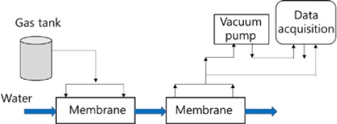
The experimental setup is shown in Figure 1. Two membranes were used in the experimental device. Water was supplied to the first membrane, and the prepared gases with the characteristics of exhaled breath were injected through the membrane and mixed with water. Water containing the prepared gases was supplied to the second membrane using a vacuum pump, and the dissolved gases were separated from water. The membranes were fabricated using 3M Liqui-Cel, and their characteristics are listed in Table 1. The gases injected through the membrane were mixed with water to generate scattered bubbles, and the contact area between the scattered gas bubbles and water increased, thereby making it easier for the gases to come into contact with water. More CO2 in the mixed gas was dissolved in water. The gases with large bubbles passed through the membrane without dissolving in water, and the CO2 concentration in the dissolved gas decreased. The CO2 concentration decreased as the scattering increased. Numerous hollow fibers were arranged in the membrane in the form of an array with even spacing between the fibers, and the prepared gases were easily scattered into the water using these fibers.
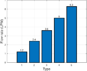
The dissolved gases were separated from water in the second membrane using a vacuum pump. The flow rate and vacuum pressure of the separated gases were recorded using a measurement system. The prepared gases were mixed with water at five flow rates, as shown in Figure 2.
3. Results and Discussion
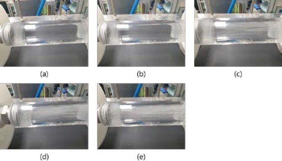
Figure 3 shows the mixed state after the prepared gases were injected through the first membrane when water was supplied at a flow rate of 20 LPM. Bubbles were not visible to the naked eye when the flow rate of the prepared gases was below 3.6 LPM. Bubbles appeared at a flow rate of 3.6 LPM, and thereafter, the number of bubbles increased with the flow rate. The absence of air bubbles below 3.6 LPM. indicated that the prepared gases mixed well with water in the form of small bubbles without lumps. The membrane increased the contact area of the gases with water.
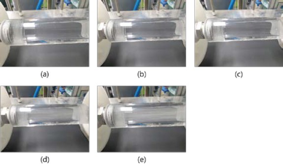
Figure 4 shows the mixed state after the prepared gases were passed through the first membrane and water was supplied at 30 LPM. No bubbles were visible when prepared gases were injected at 3.6 LPM, and bubbles appeared above 5 LPM. As the amount of water was increased, the contact area with the bubbles increased. This was expected to increase the amount of dissolved gases separated through the second membrane.
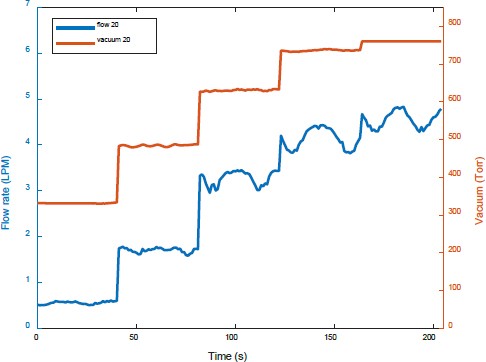
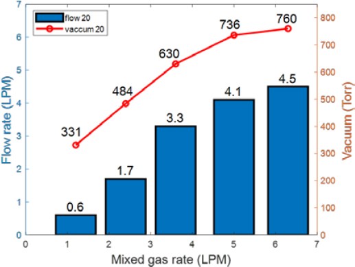
Figure 5 shows the flow rate and pressure of the separated dissolved gases as the injection flow rate of the prepared gases was increased from 1.2 LPM to 6.3 LPM and the flow rate of water was 20 LPM. The amount of separated gases increased with the amount of prepared gases. Furthermore, the vacuum pressure at each stage decreased as the amount of prepared gases increased. When the injection flow rate of prepared gases was 5 LPM or more, the increase in the amount of separated gases was less even if more prepared gases were added. This could be because more prepared gases were discharged through the second membrane.
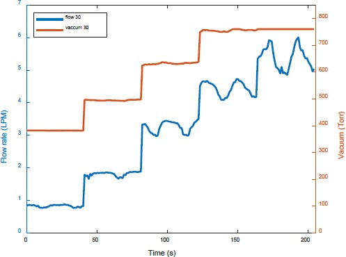
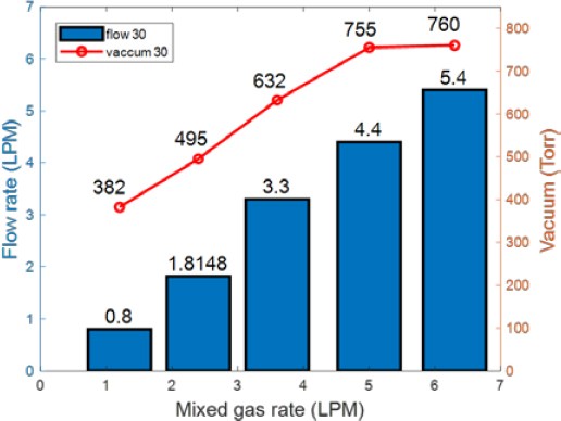
Figure 6 shows the amount of separated gases and the vacuum pressure measured while increasing the injected amount of prepared gases at a water flow rate of 30 LPM. When the injected amount of prepared gases was low, the observed trends were similar to those shown in Figure 5. However, the amount of separated dissolved gases increased with the injected amount of prepared gases. When prepared gases were injected at a flow rate of 6.3 LPM, more dissolved gases were separated compared to that at a water flow rate of 20 LPM.
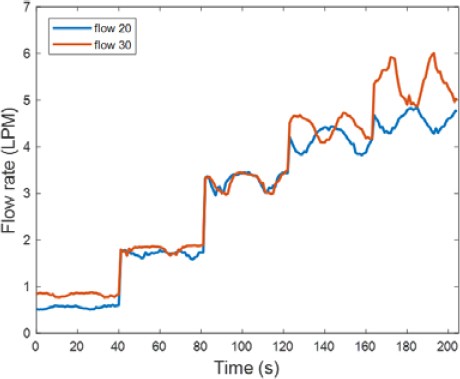
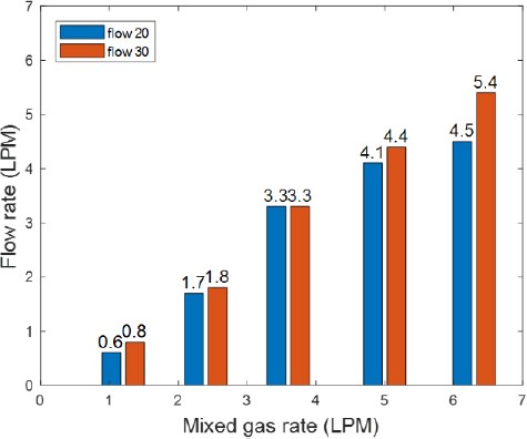
The average of the experimental data was calculated to quantify the amount of separated dissolved gases. Figure 7 shows the amount of separated gases when water was supplied at 20 LPM and 30 LPM. At 30 LPM, when the injected amount of prepared gases was low, the amount of separated dissolved gases was slightly higher. When 6.3 LPM of prepared gases were added, the amount of separated dissolved gases was so large that the difference was visible to the naked eye, as compared to when 20 LPM water was supplied.
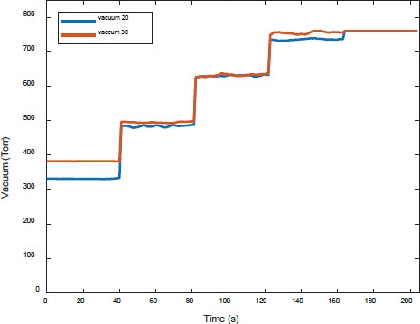
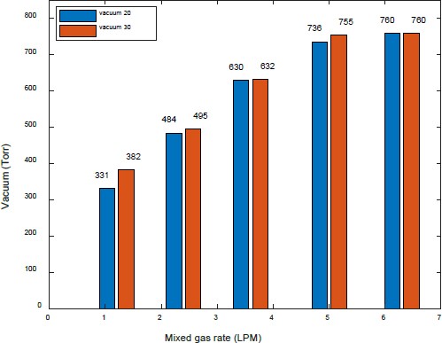
Figure 8 compares the vacuum pressure when water was supplied at 20 LPM water and 30 LPM. The trend was similar to the characteristics, indicating the flow rate of separated gases.
Figures 9 and 10 show the flow rates and vacuum pressure of the separated dissolved gases obtained using increasing amounts of the prepared gases at water flow rates of 20 LPM and 30 LPM, respectively. When prepared gases were injected at 6.3 LPM, the vacuum pressure was the same at 760 Torr. However, the amount of separated dissolved gases at a water flow rate of 30 LPM was more than that at 20 LPM.
Figures 11 and 12 show a comparison of the amount of separated gases and vacuum pressure, respectively, when water was supplied at 20 LPM and 30 LPM.
4. Conclusion
Gases with the characteristics of exhaled breath were prepared and mixed with water using hollow fibers. Bubbles were not visible to the naked eye when the injection flow rate of prepared gases was low, and bubbles appeared when the flow rate was more than 3.6 LPM. Thereafter, the number of bubbles increased with the flow rate. The amount of separated dissolved gases increased with the injection flow rate of prepared gases up to 5 LPM. The flow rate of separated gases increased slightly when the flow rate was increased beyond 5 LPM. When water was supplied at 30 LPM and the prepared gases were mixed with water using hollow fibers, bubbles appeared when the flow rate of prepared gases was 3.6 LPM. As the flow rate of prepared gases increased beyond 3.6 LPM, the amount of separated dissolved gases also increased. When the prepared gases were mixed with water supplied at 20 LPM, the amount of separated gases increased. The increase in the amount of separated gases reduced when the flow rate of prepared gases was increased beyond 5 LPM. When prepared gases were mixed with water supplied at 30 LPM, the amount of separated dissolved gases increased compared to that at 20 LPM.
Acknowledgments
This research was supported by a research project (Development of Underwater Breathing Device Technology without An Oxygen Tank, 20026073) the Korea Evaluation Institute of Industrial Technology (KEIT) under the Korea government Ministry of Knowledge Economy.
Author Contributions
Conceptualization, P. W. Heo; Methodology, P. W. Heo; Software, P. W. Heo; Formal Analysis, P. W. Heo; Investigation, P. W. Heo; Resources, P. W. Heo; Data Curation P. W. Heo; Writing-Original Draft Preparation, P. W. Heo; Writing-Review & Editing, P. W. Heo; Visualization, P. W. Heo; Supervision, P. W. Heo; Project Administration, P. W. Heo; Funding Acquisition, P. W. Heo.
References
-
M. R. Flynn and J.W.M. Bush, “Underwater breathing: The mechanics of plastron respiration,” Journal of Fluid Mechanics, vol. 608, pp. 275-296, 2008.
[https://doi.org/10.1017/S0022112008002048]

-
Velianti, S. B. Park, and P. W. Heo, “The enhancement of oxygen separation from the air and water using poly(vinylidene fluoride) membrane modified with superparamagnetic particles,” Journal of Membrane Science, vol. 466, pp. 274-280, 2014.
[https://doi.org/10.1016/j.memsci.2014.04.043]

-
J. Lee, P. W. Heo, T. Kim, “Theoretical model and experimental validation for underwater oxygen extraction for realizing artificial gills,” Sensors and Actuators A: Physical, vol. 284, pp. 103-111, 2018.
[https://doi.org/10.1016/j.sna.2018.09.071]

-
P. W. Heo, “Separation characteristics of gases from water including small sized unused gases through power-free mixing,” Journal of Advanced Marine Engineering and Technology, vol. 45, no. 6, pp. 442-446, 2021.
[https://doi.org/10.5916/jamet.2021.45.6.442]

-
P. W. Heo, “Composition of mixed gas with exhalation characteristics separated by dissolved gas separator with multi-stage passive mixer,” Journal of Advanced Marine Engineering and Technology, vol. 46, no. 5, pp. 270-276, 2022.
[https://doi.org/10.5916/jamet.2022.46.5.270]


