Study on improving the insulation performance of insulation gaskets for shipbuilding and offshore plant piping
Copyright © The Korean Society of Marine Engineering
This is an Open Access article distributed under the terms of the Creative Commons Attribution Non-Commercial License (http://creativecommons.org/licenses/by-nc/3.0), which permits unrestricted non-commercial use, distribution, and reproduction in any medium, provided the original work is properly cited.
Abstract
Gaskets play a crucial role in preventing leakage and seepage when they are inserted and bolted into the flange joints of piping systems, such as those in shipbuilding, offshore plants, and marine engines. The application of conventional gaskets in pipelines can lead to galvanic corrosion between dissimilar materials over time, which can result in leakage of high-temperature and high-pressure fluids due to corrosion. This increases the likelihood of secondary accidents. In recent years, the demand for insulation gaskets to prevent galvanic corrosion has increased. The ability of insulation gaskets to prevent corrosion varies depending on their insulation performance. In this study, the structures and materials of the most widely used insulation gaskets developed overseas were analyzed. Additionally, a new structure and material for insulation gaskets were proposed. Electromagnetic field analysis simulations were conducted by modeling the application of advanced products and proposed insulation gaskets. Furthermore, physical tests were performed by installing actual gaskets to confirm the extent of improvement in real insulation performance when applying advanced products and the proposed insulation gaskets.
Keywords:
Insulation gasket, Insulation performance, Piping, Galvanic corrosion1. Introduction
Gaskets are usually inserted into the flange joints of piping systems, such as those in shipbuilding and marine engines, and secured with bolts to prevent leakage [1]. However, over time, galvanic corrosion can occur between the flanges of various fluids, depending on the dissimilar materials used in the pipeline. Galvanic corrosion increases the likelihood of leakage of high-temperature and high-pressure fluids and, in extreme cases, can lead to secondary accidents. Insulation gaskets are used to prevent such incidents. These specialized gaskets have been classified as high-value components, the demand for which has increased exponentially in recent times [2].
The corrosion prevention capabilities of insulation gaskets vary based on their insulation performance. In this study, the structures and materials of the most widely used insulation gaskets developed overseas were analyzed. Additionally, a new structure and material for insulation gaskets are proposed to confirm the extent of improvement in the actual insulation performance.
1.1 Definition of Insulation Gaskets
Gaskets are generally classified into metallic, non-metallic, and semi-metal gaskets; semi-metal gaskets are composed of a combination of metallic and non-metallic materials. These gaskets leverage the flexibility and resilience of non-metallic materials, along with the strength and heat resistance of metallic materials. This combination allows them to exhibit excellent sealing properties under a wide range of temperature and pressure conditions [3].
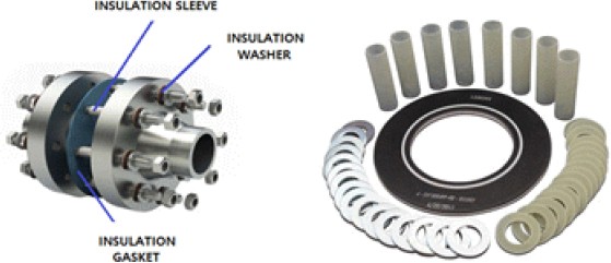
Insulation gaskets are specialized gaskets that prevent galvanic corrosion between dissimilar materials. They prevent leakage, ensure a secure seal, and provide electrical insulation [4][5]. Insulation gaskets are typically composed of insulation washers and sleeves; Additionally, they possess inherent insulation properties. Figure 1 shows the components of the insulation gasket.
1.2 Significance of Insulation Gaskets
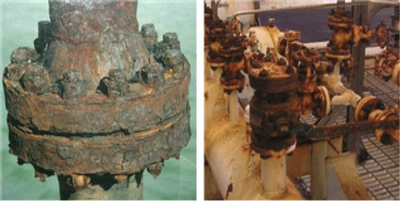
In the case of the most commonly used general or metallic gaskets, galvanic corrosion resulting from potential differences between two pipes can necessitate the replacement of the entire pipe system. Figure 2 illustrates the appearance of pipes and flanges affected by galvanic corrosion.
In shipbuilding and offshore plants, corrosion can result in significant direct and indirect cost losses due to downtime shutdowns for pipe and flange replacement, as well as labor costs. In the case of shipbuilding and offshore plants, significant direct and indirect costs are incurred due to corrosion, necessitating the replacement of pipes and flanges. Direct costs include the expense of replacing corroded structures and flanges; the cost of using corrosion-resistant metals or alloys if the existing metal lacks sufficient corrosion resistance; and additional costs for plating, corrosion inhibitors, and devices for corrosion prevention. Indirect costs involve the operational halt of the facility to replace corroded flanges, resulting in the loss of functionality, labor costs, waste of production material, and pollution because the corrosion of flanges causes the loss of oil, water, gas. In addition, there are indirect losses, such as pipe blockage due to accumulated corrosion products and the contamination of manufactured products due to the incorporation of corrosion by-products.
2. The Structure of the Proposed Insulation Gasket
2.1 The Structure of the Conventional Insulation Gasket from Advanced Overseas Manufacturers
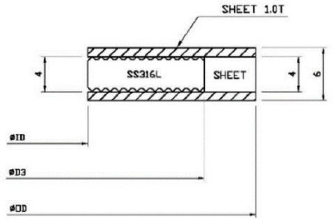
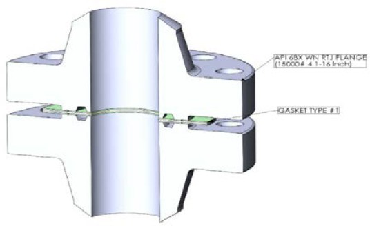
A gasket with the highest market share overseas, which is rated for 50 bar, was selected as the reference gasket for comparison. For advanced foreign manufacturers, the gasket structure typically consists of SS316L and mica sandwiched between two Epoxy G-10 layers. Figure 3 illustrates the structure of the gaskets used by advanced manufacturers.
2.2 The Proposed Insulation Gasket Structure
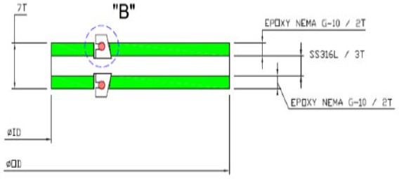
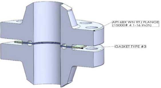
The proposed insulation gasket is rated at a pressure of 50 bar. In contrast to conventional advanced manufacturers that use mica for insulation, the proposed structure incorporates polytetrafluoroethylene (PTFE), which offers insulation properties superior to those of mica. This modification aims to enhance insulation performance. To analyze the improvement with the application of PTFE, the external sheet followed the same approach as that followed by advanced manufacturers, using Epoxy G-10. Figure 4 illustrates the structure of the proposed gasket.
3. Electromagnetic Field Analysis Simulation
3.1 Modeling
Electromagnetic field analysis simulations were conducted to assess the insulation performance of the insulation gaskets from advanced overseas manufacturers and the proposed insulation gaskets. 3D modeling was performed to facilitate the simulations. The 3D model represented the assembly of the gasket between the two flanges, with the material of the flanges and bolts determined to be SS304. Figure 5 depicts the modeling results for a gasket from advanced overseas manufacturers, Figure 6 illustrates the modeling results for the proposed gasket, and Table 1 lists the material properties for the electromagnetic field analysis simulation. No different temperature conditions were considered in the comparison to assess the insulation performance of two insulation gaskets with identical specifications.
3.2 Results of Electromagnetic Field Analysis
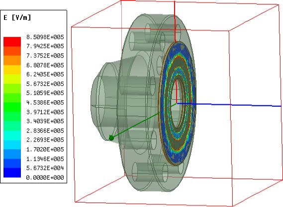
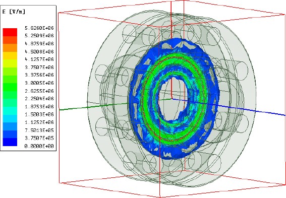
The electromagnetic field analysis simulation used the ANSYS Electronics program, and the point of the maximum electric field (Max. E Field) can be examined in the solution data. For the insulation gasket from advanced overseas manufacturers, the strongest electric field, measuring 1,448.7 [kV/m], was formed within the mica mixed between two Epoxy G-10 layers. In contrast, for the proposed insulation gasket, the electric field was concentrated on the PTFE portion inserted within the Epoxy G-10, and was recorded at 804.9 [kV/m], indicating a lower electric field compared to the advanced overseas manufacturer's gasket. This suggests that the proposed insulation gasket structure provides stable insulation performance. Figure 7 depicts the electromagnetic field analysis results for the advanced overseas manufacturer’s, insulation gaskets, and Figure 8 illustrates the results for the proposed insulation gasket.
4. Insulation Performance Test Results
4.1 Test Items and Test Methods
Comparative tests were conducted to assess the insulation performance. These included insulation resistance measurement tests, polarization index measurement tests, partial discharge measurement tests, and withstand voltage breakdown tests. In the insulation resistance measurement tests, a direct current (DC) of 1,500 V was applied and the values were measured after 1 min. In the tests to measure the polarization index measurement tests a DC of 1,500 V was applied, the values were measured after 1 and 10 min, and the polarization index was calculated. In the partial discharge measurement tests, the partial discharge inception voltage was determined, whereas in the withstand voltage breakdown tests a voltage was applied until insulation breakdown occurred, whereby the breakdown voltage was measured. Table 2 summarizes the test items and the methods used.
4.2 Sample Installation and Testing Equipment
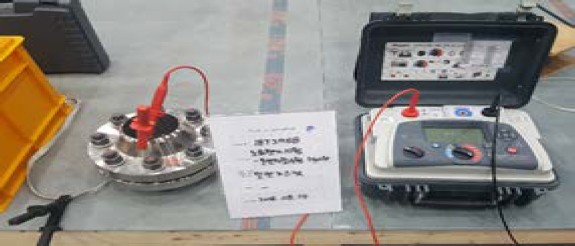
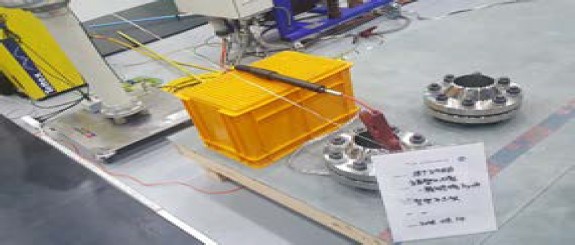
Two samples were fabricated, each of which was inserted between two flanges of the same material and size. One sample featured an insulation gasket from a leading overseas manufacturer and the other featured the proposed insulation gasket. The tests conducted included insulation resistance measurements, polarization index measurements using Megger's MIT1525, partial discharge testing using Tettex's Midas2881g and Haefely's DDX 9121b, and breakdown voltage testing using Tettex's Midas2881g. Figure 9 shows photographs of the insulation resistance and polarization index testing, whereas Figure 10 displays photographs of the partial discharge and breakdown voltage tests.
4.3 Test Result
Table 3 lists the measured values for each test item. The insulation resistance value of the insulation gasket from the advanced overseas manufacturer was 146.3 GΩ, while the proposed insulation gasket was improved to 430.0 GΩ. The polarization index of the insulation gasket from an advanced overseas manufacturer was 1.21, whereas that of the proposed insulation gasket was improved to 1.72. It was confirmed that the partial-discharge inception voltage and insulation breakdown voltage were almost the same.
5. Conclusion
In this paper, a structure for enhancing the insulation performance of insulation gaskets for piping systems in shipbuilding and offshore plants is proposed. A comparative 3D modeling and electromagnetic field analysis were conducted to compare the structures of widely used insulation gaskets from advanced overseas manufacturers with those of the proposed insulation gasket. The electromagnetic field analysis results indicated that the proposed structure exhibited a lower maximum electric field strength, demonstrating stable performance in terms of insulation. Real-world tests with the installed gaskets showed an approximately three-fold improvement in insulation resistance and a 1.4-fold improvement in the polarization index compared to the values obtained with the widely used insulation gasket. In the future, I plan to investigate the extent of insulation improvement in insulation gaskets with different specifications that are being commercialized.
Acknowledgments
This research was supported by the Ministry of Trade, Industry & Energy (MOTIE), Korea Planning & Evaluation Institute of Industrial Technology (KEIT) through Innovative Green Ship Technology Development (RS-2023-00252794).
Author Contributions
Conceptualization, H. C. Kim; Methodology, H. C. Kim and J. S. Kim; Formal Analysis, H. C. Kim; Investigation, H.C. Kim and J. S. Kim; Resources, H. C. Kim and J. S. Kim; Data Curation H. C. Kim; Writing-Original Draft Preparation, H. C. Kim; Writing-Review & Editing, H. C. Kim and J. S. Kim; Visualization, H. C. Kim; Supervision, H. C. Kim and J. S. Kim; Project Administration, J. S. Kim; Funding Acquisition, H. C. Kim and J. S .Kim.
References
- S. M. Park, S. H. Lee, S. G. Kim, Y. H. Jin, “Development of high-temperature, high-pressure insulation gasket insulation material meeting continuous operating temperature of 260℃,” The Korean Society of Industrial and Engineering Chemistry, vol. 2020, p. 184, 2020 (in Korean).
-
J. S. Kim, J. H. Cho, J. K. Cho, Y. G. Kim, J. M. Kim, S. H. Ham, and B. S. Jung, “Study on chemical leakage detection using ECP gasket,” Journal of the Korean Society of Mechanical Technology, vol. 18, no. 6, pp. 955-960, 2016 (in Korean).
[https://doi.org/10.17958/ksmt.18.6.201612.955]

-
T. A. Kurskaya, R. S. Mikhal’chenko, V. F. Getmanets, “Highly efficient cryogenic thermal insulation for optical devices and pipelines,” Journal of Engineering Physics and Thermophysics, vol. 68, pp. 46-49, 1995.
[https://doi.org/10.1007/BF00854366]

-
T. Osakabe, Y. Kato, S. Honmoto, and K. Kuwahara, “Development of technique for electrical insulation of metallic gasket using anodic oxide coating,” Review of High Pressure Science and Technology, vol. 25, no. 1, pp. 57-63, 2015 (in Japanese).
[https://doi.org/10.4131/jshpreview.25.57]

-
R. H. Araujo, L. P. Romano, J. C. Veiga, and A. C. Silva, “Development of gaskets and its accessories for electrical insulation of pipelines,” Proceedings of the ASME Pressure Vessels and Piping Conference, vol. 3, 2016.
[https://doi.org/10.1115/PVP2016-63573]

-
C. Q. Li and M. Mahmoodian, “Risk based service life prediction of underground cast iron pipes subjected to corrosion,” Reliability Engineering & System Safety, vol. 119, pp. 102-108, 2013.
[https://doi.org/10.1016/j.ress.2013.05.013]

-
W. Tian, N. Du, S. Li, S. Chen, and Q. Wu, “Metastable pitting corrosion of 304 stainless steel in 3.5% NaCl solution,” Corrosion Science, vol. 85, pp. 372-379, 2014.
[https://doi.org/10.1016/j.corsci.2014.04.033]

-
R. B. Polder, G. Leegwater, D. Worm, and W. Courage, “Service life and life cycle cost modelling of cathodic protection systems for concrete structures,” Cement and Concrete Composites, vol. 47, pp. 69-74, 2014.
[https://doi.org/10.1016/j.cemconcomp.2013.05.004]

-
E. Redaelli, F. Lollini, and L. Bertolini, “Throwing power of localized anodes for the cathodic protection of slender carbonated concrete elements in atmospheric conditions,” Construction and Building Materials, vol. 39, pp. 95-104, 2013.
[https://doi.org/10.1016/j.conbuildmat.2012.05.014]

-
J. A. Jeong and C. K. Jin, “The effect of temperature and relative humidity on concrete slab specimens with impressed current cathodic protection system,” Journal of the Korean Society of Marine Engineering, vol. 37, no. 3, pp. 260-265, 2013.
[https://doi.org/10.5916/jkosme.2013.37.3.260]

-
S. K. Jang, M. S. Han, and S. J. Kim, “Electrochemical characteristics of stainless steel using impressed current cathodic protection in seawater,” Transactions of Nonferrous Metal Society of China, vol. 19, no. 4, pp. 930-934, 2009.
[https://doi.org/10.1016/S1003-6326(08)60380-5]


