Object transportation using multiple mobile robots: Coupling and decoupling configuration of an object and robots
Copyright © The Korean Society of Marine Engineering
This is an Open Access article distributed under the terms of the Creative Commons Attribution Non-Commercial License (http://creativecommons.org/licenses/by-nc/3.0), which permits unrestricted non-commercial use, distribution, and reproduction in any medium, provided the original work is properly cited.
Abstract
This study deals with object transportation using multiple mobile robots. Each robot is assumed to have a mechanism to couple with an object. The mechanism is operated by pushing and pulling forces without an actuator and becomes a free joint after coupling. The transportation operation is conducted as follows. The mobile robots first couple with the object using pushing motions. Then, they transport the object to the goal position. Finally, they decouple from the object using pulling motions after arriving at the destination. In this study, we focus on coupling and decoupling operations and discuss the configurations of the object and robots for coupling and decoupling. First, we formulate a kinematic model and static equilibrium equation for the object and n robots and then show that there exists a configuration, in which the robots can push and pull one another for coupling and decoupling while maintaining static equilibrium. Such a configuration is a singular configuration and is usually regarded as undesirable in terms of motion control. It is demonstrated through numerical examples using two, three, and four robots that the singular configuration is appropriate for coupling and decoupling operations.
Keywords:
Object transportation, Multiple robots, Coupling and decoupling, Singular configuration, Mobile robot1. Introduction
In ports, warehouses, factories, and restaurants, mobile robots carrying goods or food are common. However, most of these robots are designed to handle objects with limited size, shape, and weight. Furthermore, the process of loading goods or food onto the robots requires human intervention. The common action of moving refrigerators or furniture in our daily lives is a pushing or pulling motion, and through this motion, we can move large and heavy objects with relatively small force without additional measures for transportation. This study deals with object transportation using multiple mobile robots, which makes the transport of objects in different sizes, shapes, and weights possible through pushing and pulling motions.
Many studies have been conducted in the fields of modern logistics and automated transportation on multirobot cooperation [1]–[15]. Cooperative operation by multiple robots is important when handling bulky and heavy objects because these tasks may be too arduous or dangerous for individual robots or humans. Techniques, such as pushing, grasping, and caging, have proven to be reliable methods for multirobot cooperation to address such challenges [1][2].
The movement of target objects by multiple robots directly applying pushing forces has been demonstrated [3]-[6]. The effectiveness of this method lies in the distribution of the required forces, thereby reducing the burden on individual to manipulate large objects. Grasping technology relies on the ability of robots to grasp an object securely and then move it collaboratively. This method is suitable for objects that are easily held and require precise handling. It has been shown that the grasping approach ensures operational stability and efficiency, and prevents the object from falling or overloading. The caging method uses multiple robots to form an enclosed structure and transport objects. This approach is particularly suitable for objects with irregular shapes or the ones, which are difficult to directly grasp [10]-[14].
Implementing robotic transportation in the real world provides many advantages; however, there are challenges, including precise control, environmental adaptability, inter-robot communication, and decision-making [15]. The size, shape, and weight of objects, along with environmental factors, such as terrain and space constraints, also influence transportation approaches.
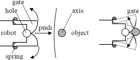
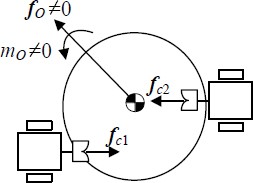
This study considers the multi-robot cooperative object transportation, as shown in Figure 1, to handle objects of various sizes, shapes, and weights. Unlike pushing, grasping, and caging methods, robots use a mechanism to couple with an object, which makes transportation control easier. The mechanism is operated by applying pushing and pulling forces without an actuator, which become a free joint after coupling. The transportation operation is conducted as follows. The mobile robots first couple with the object using pushing motions. Then, they transport the object to the goal position, and finally decouple from the object using pulling motions after arriving at the destination.
In this study, we focus on the coupling and decoupling operations and discuss the configurations of an object and robots for coupling and decoupling. Sections 2 and 3 present the formulation of the kinematic model and static equilibrium equation, respectively. In Section 4, it is shown that there exist configurations, in which the robots can push and pull one another for coupling and decoupling without generating a moment on the object. These configurations are singular configurations and are usually regarded as undesirable in the motion control aspect. Numerical examples are presented and discussed in Section 5 to verify the coupling and decoupling configurations.
2. Kinematic Model
Assume that the mechanism shown in Figure 2 is used for coupling and decoupling. Coupling is achieved by pushing when the gates are in contact with the axis attached to the object, and decoupling is achieved by the reverse action.
Consider an object in contact with n mobile robots, as shown in Figure 3. Let vo ∈ ℜ2 and ωo ∈ ℜ be the linear and angular velocities of the object, respectively, ri ∈ ℜ2 (i = 1, 2, ⋯ , n) be the position vector pointing from the center of mass of the object to the contact point with the robot i, and vci ∈ ℜ2 be the velocity of the contact point. Because vci = vo + Eriωo, we get
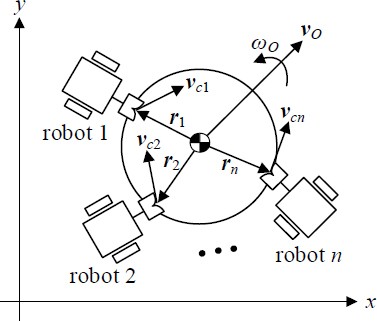
Velocity relationship when n number of robots are contact with object (coupling mechanism of each robot is in contact with the axis at the object)
| (1) |
where, I2, is a 2 × 2 identity matrix, and E is the orthogonal rotation matrix rotating an arbitrary vector counterclockwise by 90o in a plane and is expressed as:
| (2) |
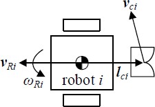
The contact point velocities can also be obtained from the linear and angular velocities of each robot. Let vRi ∈ ℜ2 and ωRi ∈ ℜ be the linear and angular velocities of the robot i, respectively (refer to Appendix A.1 for obtaining vRi and ωRi from the angular velocities of the wheels) and lci ∈ ℜ2 is the position vector pointing from the center of mass of the robot to the end of the coupling mechanism, i.e., the contact point. From Figure 4 and vci = vRi + ElciωRi, we get
| (3) |
where,
O 2 is a 2 × 2 zero matrix, and 0 is a 2 × 1 zero vector.
From Equations (1) and (3), we can obtain the velocity constraints as:
| (4) |
Here, to consider only the pushing and pulling motions for coupling and decoupling, the angular velocities ωRi are moved to the left side of Equation (4), and the following kinematic model can be obtained.
| (5) |
where, , and .
3. Static Equilibrium Equation
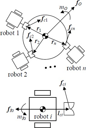
Let fo ∈ ℜ2 and mo ∈ ℜ be the force and moment generated on the object, respectively, fRi ∈ ℜ2 and mRi ∈ ℜ be the force and moment of the robot i, respectively (refer to Appendix A.2 for obtaining fRi and mRi from the torques of the motors attached at the wheels), and fci ∈ ℜ2 (i = 1, 2, ⋯ , n) be the force generated at the contact point. From Figure 5, we obtain the following static equilibrium equation for the object as:
| (6) |
where, and . Here, the contact force fci can be exerted by robot i and we obtain:
| (7) |
This relation can be expressed for all the robots as:
| (8) |
where, .
Combining the τo in Equation (6) and equations related with mRi in Equation (8), the static equilibrium condition for pushing and pulling can be obtained as:
| (9) |
where, .
4. Coupling and Decoupling Configuration
As shown in Figures 1 and 2, coupling and decoupling are performed using pushing and pulling motions. Thus, such actions must be achieved without generating a moment on the object; otherwise, the motion of the object becomes unstable, and the robots can detach from the object.
From Equation (5), when rank(A) < min(2n, 3 + n), there exists (output) even if vR = 0 (input). This is a singular configuration. On the contrary, from Equation (9), if dimKer(AT) ≠ 0, we have
| (10) |
This indicates that there exists a certain contact force fc that maintains static equilibrium without exerting force and moment on the object (τo = 0) and moments on the robots (mRi =0). Thus, it can be concluded that a configuration satisfying the following conditions is appropriate for pushing and pulling one another for coupling and decoupling.
| (11) |
In this case, the contact force fc can be obtained as:
| (12) |
where, h is the basis of Ker(AT) and γ is a real number. In addition, the force and moment exerted by each robot to accomplish coupling and decoupling can be obtained using Equation (8).
5. Numerical Examples
5.1 Using Two Robots
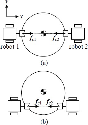
Consider Cases (a) and (b), as shown in Figure 6. Table 1 presents the values of ri and lci. From Equation (5), if two robots are used, i.e., n = 2, we have:
| (13) |
First, in the case of Figure 6(a), rank(A) = 3 < min(4, 5) and dimKer(AT) = 1, thus, this configuration is a singular configuration, and certain contact forces exist to push and pull each other while maintaining static equilibrium. Equation (12) gives fc = (-0.7071, 0, 0.7071, 0)Tγ; the robots can pull each other for decoupling if γ is a positive real number and push for coupling if γ is a negative. Equation (8) yields the forces and moments of the robots to exert fc : τR = (-0.7071, 0, 0, 0.7071, 0, 0)Tγ , where, γ is positive for decoupling (pulling) and negative for coupling (pushing).
Next, in the case of Figure 6(b), rank(A) = 3 < min(4, 5), dimKer(AT) = 1 , and fc = (–0.7071, 0, 0.7071, 0)Tγ . It is known that this configuration is singular and appropriate for coupling and decoupling. For this case, the force and moment of the robots are τR = (-0.7071, 0, 0, 0.7071, 0, 0)Tγ. However, if r2 is changed to (0.4, 0)T as shown in Figure 7, rank(A) = 4 = min(4, 5) and dimKer(AT) = 0. Hence, the configuration is not singular, and there are no contact forces for static equilibrium. Figure 7 shows that the contact forces exert a moment on the object in this configuration.
5.2 Using Three Robots
The four configurations and parameter values are given in Figure 8 and Table 2, respectively. If three robots are used (n = 3), we obtain:
| (14) |
Checking the case of Figure 8(a), rank(A) = 5 < min (6, 6), dimKer(AT) = 1 , fc = (–0.5, –0.2887, 0.5, –0.2887, 0, 0.5774)Tγ , and τR = (–0.5, –0.2887, 0, 0.5, –0.2887, 0, 0, 0.5774, 0)Tγ, where, γ is positive for decoupling and negative for coupling. The configuration is singular, and robots can push and pull one another for coupling and decoupling. In this case, the contact forces meet at the center of mass of the object. Unlike this, Figure 8(b) is the case when the contact forces meet at another place. This configuration is proper for coupling and decoupling; we can confirm this by rank(A) = 5 < min (6, 6) , dimKer(AT) = 1, fc = (–0.3536, –0.3536, 0.3536, –0.3536, 0, 0.7071)Tγ, and τR = (–0.3536, –0.3536, 0, 0.3536, –0.3536, 0, 0, 0.7071, 0)Tγ.
In case of Figure 8(c), rank(A) = 5 < min (6, 6) , dimKer(AT) = 1 , fc = (0.7071, 0, –0.7071, 0, 0, 0)Tγ , and τR = (0.7071, 0, 0, –0.7071, 0, 0, 0, 0, 0)Tγ, where, γ is positive for coupling and negative for decoupling. This configuration has a local singular configuration and is appropriate for the coupling and decoupling of Robots 1 and 2. However, Robot 3 cannot exert a contact force for coupling and decoupling.
In addition, if a robot must be decoupled from the object, the configuration shown in Figure 8(d) can be used. In this case, rank(A) = 5 < min (6, 6) , dimKer(AT) = 1 , fc = (0.3536, –0.3536, –0.3536, –0.3536, 0, 0.7071)Tγ , and τR = (0.3536, –0.3536, 0, –0.3536, –0.3536, 0, 0, 0.7071, 0)Tγ . When γ is a positive, Robot 3 can decouple from the object by pulling motion, while the other robots push the object.
5.3 Using Four Robots
When we use four robots (n = 4),
| (15) |
From rank(AT) + dimKer(AT) = 8 , it can be known that dimKer(AT) ≠ 0 even if rank(A) = rank(AT) = 7 = min(8,7); this means that the robots can push and pull one another for coupling and decoupling at any configuration; however, there is a configuration, at which specific robot(s) cannot exert a contact force for coupling and decoupling like Robot 3, as shown in Figure 8(c). This result can be applied to cases, in which more than four robots are used.
6. Conclusion
In this study, we discussed the coupling and decoupling configuration of an object and robots for cooperative object transport. The following conclusion were drawn:
- (1) When two or three robots are used, a singular configuration is appropriate for coupling and decoupling, because forces exist that push and pull one another without generating a moment on the object.
- (2) When more than three robots are used, coupling and decoupling operations can be achieved regardless of the formation of a singular configuration.
- (3) A specific robot or some robots out of all the robots can couple/decouple with/from the object using at a local singular configuration.
Our future work will involve conducting experimental verification and developing a path-following control method for multirobot cooperative object transportation.
Author Contributions
Conceptualization, J. -K. Choi; Methodology, J. -K. Choi; Software, J. -K. Choi and H. Tian; Formal Analysis, J. -K. Choi, H. Tian and Y. -S. Ha; Investigation, J. -K. Choi and H. Tian; Resources, J. -K. Choi and H. Tian; Data Curation J. -K. Choi and H. Tian; Writing-Original Draft Preparation, J. -K. Choi and H. Tian; Writing-Review & Editing, J. -K. Choi, H. Tian and Y. -S. Ha; Visualization, J. -K. Choi and H. Tian; Supervision, J. -K. Choi.
References
-
E. Tuci, M. H. M. Alkilabi, and O. Akanyeti, “Cooperative object transport in multi-robot systems: A review of the state-of-the-art,” Frontiers in Robotics and AI, vol. 5, pp. 2-8, 2018.
[https://doi.org/10.3389/frobt.2018.00059]

-
H. Ebel and P. Eberhard, “Non-prehensile cooperative object transportation with omnidirectional mobile robots: Organization, control, simulation, and experimentation,” 2021 International Symposium on Multi-Robot and Multi-Agent Systems (MRS), pp. 1-2, 2021.
[https://doi.org/10.1109/MRS50823.2021.9620541]

- M. Matarić, M. Nilsson, and K. Simsarian, “Cooperative multi-robot box-pushing,” Proceedings of 1995 IEEE/RSJ International Conference on Intelligent Robots and Systems, vol. 3, pp. 556-560, 1995.
- Y. U. Cao, A. S. Fukunaga, A. B. Kahng and F. Meng, “Cooperative mobile robotics: Antecedents and directions," Proceedings of 1995 IEEE/RSJ International Conference on Intelligent Robots and Systems. Human Robot Interaction and Cooperative Robots, vol. 1, pp. 226-233, 1995.
-
S. Akella and M. T. Mason, “Posing polygonal objects in the plane by pushing,” The International Journal of Robotics Research, vol. 17, no. 1, pp. 70-88, 1998.
[https://doi.org/10.1177/027836499801700107]

-
J. Zhou, Y. Hou, and M. T. Mason, “Pushing revisited: Differential flatness, trajectory planning, and stabilization,” The International Journal of Robotics Research, vol. 38, no. 12-13, pp. 1477-1489, 2019.
[https://doi.org/10.1177/0278364919872532]

- D. Rus, B. Donald and J. Jennings, “Moving furniture with teams of autonomous robots,” Proceedings of 1995 IEEE/RSJ International Conference on Intelligent Robots and Systems, vol. 1, pp. 235-242, 1995.
- J. Sasaki, J. Ota, E. Yoshida, D. Kurabayashi, and T. Arai, “Cooperating grasping of a large object by multiple mobile robots,” Proceedings of IEEE International Conference on Robotics and Automation, vol. 1, pp.1205-1210, 1995.
-
D. Mellinger, M. Shomin, N. Michael, and V. Kumar, “Cooperative grasping and transport using multiple quadrotors,” Distributed Autonomous Robotic Systems: The 10th International Symposium, pp. 545-558, 2013.
[https://doi.org/10.1007/978-3-642-32723-0_39]

-
M. H. M. Alkilabi, A. Narayan, and E. Tuci, “Cooperative object transport with a swarm of e-puck robots: Robustness and scalability of evolved collective strategies,” Swarm Intelligence, vol. 11, pp. 186-207, 2017.
[https://doi.org/10.1007/s11721-017-0135-8]

-
G. Eoh, J. D. Jeon, J. S. Choi, and B. H. Lee, “Multi-robot cooperative formation for overweight object transportation,” 2011 IEEE/SICE International Symposium on System Integration, pp. 726-731, 2011.
[https://doi.org/10.1109/SII.2011.6147538]

- Z. Wang and V. Kumar, “Object closure and manipulation by multiple cooperating mobile robots,” Proceedings of IEEE International Conference on Robotics and Automation, vol. 1, pp. 394-399, 2002.
- Z. D. Wang, Y. Hirata and K. Kosuge, “Control multiple mobile robots for object caging and manipulation,” Proceedings of IEEE/RSJ International Conference on Intelligent Robots and Systems, vol. 2, pp. 1751-1756, 2003.
- A. Sudsang and J. Ponce, “A new approach to motion planning for disc-shaped robots manipulating a polygonal object in the plane,” Proceedings of IEEE International Conference on Robotics and Automation, vol. 2, pp. 1068-1075, 2000.
-
X. An, C. Wu, Y. Lin, M. Lin, T. Yoshinaga and Y. Ji, “Multi-robot systems and cooperative object transport: communications, platforms, and challenges” IEEE Open Journal of the Computer Society, vol. 4, pp. 23-33, 2023.
[https://doi.org/10.1109/OJCS.2023.3238324]

Appendix
A.1 vRi and ωRi in Equation (3)
Consider a mobile robot with wheels on the right and left sides. Let ωri , ωli , vri , vli , L and r be the angular velocities of the right and left wheels, linear velocities generated by the angular velocities, distance between the center of mass and center of the wheel, and radius of the wheels, respectively. From vri = rωri and vli = rωli, we can obtain the linear and angular velocities of the robot i :
| (A.1) |
A.2 fRi and mRi in Equation (7)
Let τri, τli, fri and fli be the torques generated by the motors attached at the right and left wheels, and forces by the torques, respectively. Because and , we get:
| (A.2) |


