Effects of substrate roughness on corrosion resistance of electrodeposited calcareous films
Copyright © The Korean Society of Marine Engineering
This is an Open Access article distributed under the terms of the Creative Commons Attribution Non-Commercial License (http://creativecommons.org/licenses/by-nc/3.0), which permits unrestricted non-commercial use, distribution, and reproduction in any medium, provided the original work is properly cited.
Abstract
This study explores the impact of substrate roughness on the adsorption of calcareous films through electrodeposition on substrates with roughness values of 1.0 μm and 0.3 μm. Test specimens were systematically fabricated by varying the roughness, electrodeposition time, and applied current density. The morphology of the fabricated samples was analyzed using scanning electron microscopy, which provided insights into their crystal size and surface characteristics. The structural properties of the deposited films were elucidated using X-ray diffraction. The corrosion behavior was systematically investigated using electrochemical polarization and 3% NaCl immersion tests. Notably, the samples electrodeposited on substrates with higher roughness exhibited larger crystallite sizes than those electrodeposited on substrates with lower roughness. The immersion experiment revealed a decrease in corrosion progression with increasing deposition time and substrate roughness. These results agree well with the results of the electrochemical corrosion test.
Keywords:
Electrodeposition, Calcareous film, Substrate roughness, Corrosion, Immersion test1. Introduction
The beneficial impact of calcareous coatings on enhancing the cathodic protection effectiveness in submerged marine structures has been widely acknowledged [1]-[3]. These coatings are formed due to the elevated pH of the electrolyte near the metal surface, induced by the cathodic current. This leads to a decrease in the solubility limit of various inorganic compounds, such as CaCO3, MgCO3, and Mg(OH)2. In addition to supporting cathodic protection, numerous research groups have reported that calcareous deposits impede the diffusion of dissolved oxygen into metal surfaces, thereby reducing the current density required for effective cathodic protection. Furthermore, literature indicates that the overall extent of uniform corrosion diminishes even in the absence of cathodic protection [4]-[6].
High-performance epoxy coatings provide effective protection for ship ballast tanks for at least 10 years [7][8]. However, numerous studies on the degradation of ship ballast tank coatings indicate that localized areas, especially the corners and joint welds, are vulnerable to corrosion because of inadequate coating adhesion and irregular coating thickness [9][10]. Moreover, the adverse environmental effects of toxic paints necessitate alternative approaches to develop corrosion protection methods that are more environmentally friendly.
In recent years, numerous investigations have focused on the generation of calcareous deposits on steel surfaces immersed in seawater, including ballast water tanks, by employing an electrochemical calcareous deposition method [11], as highlighted in [12]-[15]. These calcareous coatings predominantly develop in areas with defective epoxy coatings and utilize naturally occurring Mg and Ca cations present in seawater. Consequently, these coatings offer several advantages over conventional epoxy coatings, making them a highly promising technology for the corrosion protection of ship ballast tanks.
In this study, we investigated the influence of substrate roughness on the adsorption of calcareous films. Our findings clearly indicate that substrate roughness has a significant impact on the growth, structure, and corrosion resistance of calcareous films. We employed various analytical techniques, including XRD for structural analysis and SEM for surface morphology examination. Additionally, the corrosion resistance of the films was assessed through a 3% NaCl immersion test and anodic polarization test.
2. Experimental Method
For the calcareous deposition, we selected a cold-rolled steel sheet (SPCC, KS D 3512) with a thickness of 0.1 mm and dimensions of 70 mm × 90 mm as our substrate. The specimens designated for electrodeposition were immersed in a Ca(HCO3)2 solution, and the film properties were evaluated under different experimental conditions. The Ca(HCO3)2 solution was prepared by bubbling 20 L of water with waste oyster shells at room temperature (~22 ºC) with a flow rate of 5 L/min in a CO2 cylinder. Carbon was utilized as the anode material, while stainless steel was used as the cathode material. To examine the influence of substrate roughness on calcareous film properties, we fabricated samples with surfaces having roughness values of Ra 0.3 μm and Ra 1.0 μm under various experimental conditions.
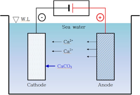
Electrodeposition experiments were conducted for 1, 3, 6, and 12 h using the deposition apparatus illustrated in Figure 1. The experiments were carried out at 0.1 and 0.4 mA/cm2, respectively using a Scientech DC power supply rectifier. The morphology and composition of the deposited samples were analyzed using field-emission scanning electron microscopy (FE-SEM; Mira3 LM, TESCAN) and energy-dispersive spectrometry (EDS) at an acceleration voltage of 15 kV. The crystal structure of the formed calcareous films was analyzed using X-ray diffraction (XRD, Ultima IV, Rigaku) with Cukα radiation.
To evaluate the corrosion resistance of the calcareously deposited film, electrochemical polarization tests were conducted using a VSP Potentiostat workstation (Biological) equipped with an Ag/AgCl reference electrode and a platinum counter electrode. The tests were performed in a 3.5% NaCl solution, with a potential range of -0.2 V to 1.2 V. In addition, immersion tests were carried out in the same 3.5% NaCl solution to further investigate the durability of the film under corrosive conditions.
3. Results and Discussion
The SEM images in Figure 2 depict calcareous films deposited at a current density of 0.40 mA/cm2 for 1, 3, 6, and 12 h under surface roughness conditions of Ra 1.0 μm and Ra 0.3 μm. The films deposited for 1 h under Ra 0.3 μm and Ra 1.0 μm did not exhibit crystallization; however, after 3 h, a fully formed rhombohedral structure was observed. Moreover, after 12 h, denser surfaces were observed under Ra 0.3 μm conditions.
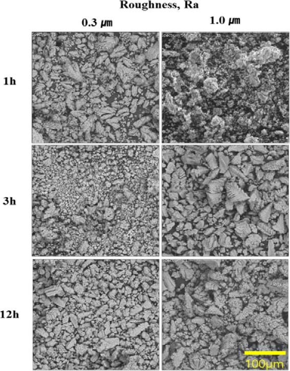
SEM morphology of the calcareous films prepared at 0.4 mA/cm² on surfaces with roughness of Ra 0.3 and Ra 1.0 μm
It is known that grain sizes are limited by the fact that crystallites grow from many nucleation centers only until they contact an adjacent grain or amorphous material. When the roughness is small, crystals start to grow on the substrate, which favors heterogeneous nucleation; however, they detach from the substrate when reaching a critical size. Meanwhile, for rougher substrates, they always remain attached to the substrate. The size of grains is constrained by a phenomenon in which crystallites develop from multiple nucleation centers until they come into contact with an adjacent grain or amorphous material. In instances of low roughness, crystals begin their growth on the substrate, exhibiting a preference for heterogeneous nucleation, but they detach once they reach a critical size [16]. Conversely, on rougher substrates, crystals consistently adhere to the substrate. This suggests that greater roughness leads to increased grain growth.
Figure 3 presents the evolution of calcium carbonate films on surfaces with roughness of Ra 1.0 μm and Ra 0.3 μm. The surface observations indicate a gradual development of a white calcite films. The results show that higher current density and prolonged adsorption time contribute to an increased film density, which results in a more pronounced white calcite film on the surface. Additionally, specimens with higher surface roughness exhibited increased formation of calcium carbonate films. This could be attributed to the larger contact area of specimens with high roughness, which creates more favorable conditions for film formation.
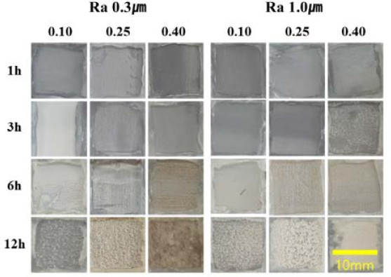
Surface morphology after electrochemical evaluation of samples deposited at surface roughness of 0.3 and 1.0 μm
Figure 4 illustrates the variations in X-ray diffraction (XRD) patterns of the calcareous deposit films electrodeposited at a current density of 0.1 mA/cm². The analysis involved test specimens with adsorption times of 1 h (a), 3 h (b), 6 h (c), and 12 h (d), conducted under the conditions of a surface roughness of Ra 1.0 μm. The presence of CaCO3, characterized by a calcite structure at 29.4–29.5°, was confirmed under all the experimental conditions. The observed data suggest a proportional increase in the adsorption amount of the calcite-structured CaCO3 compound with prolonged deposition time.
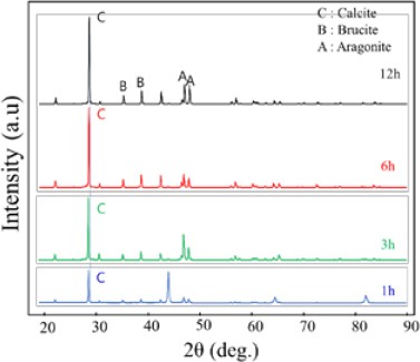
XRD pattern variations of calcareous deposit films electrodeposited on substrate with surface roughness of 0.1 μm at a current density of 0.1 mA/cm2
The electrochemical polarization behavior of the calcium carbonate film is shown in Figure 5. The samples were produced under experimental conditions with surface roughness Ra 1.0 μm and 0.3 μm and electrodeposition for 12 h, while varying the supply current density. Upon analyzing the polarization curve of the film at different roughness levels, it became evident that the corrosion current density was significantly lower. This indicated that the surface resistance was higher for the calcium carbonate film formed on a substrate with higher roughness. This is attributed to the dense and thick structure of the calcium carbonate film, which effectively blocks the external environment.
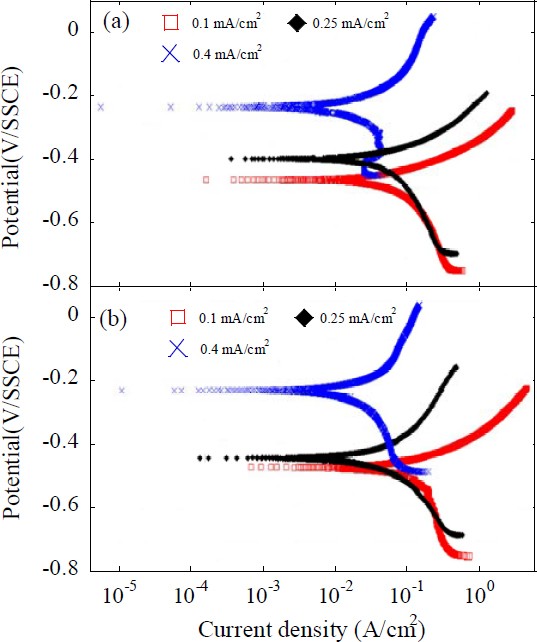
Anodic polarization curves of the calcareous films deposited for 12 h with the substrate roughness of (a) Ra 1.0 μm, (b) Ra 0.3 μm
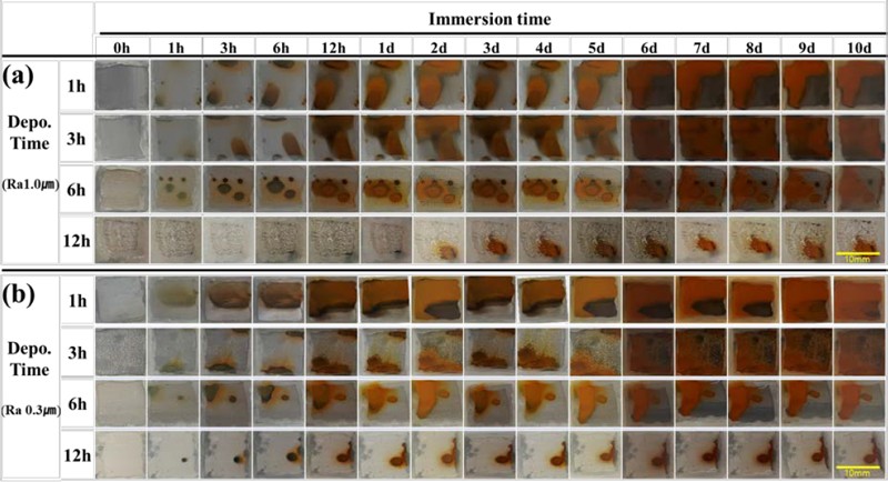
Figure 6 illustrates the progression of corrosion of the electrodeposited films in the 3% NaCl immersion test. The tests involved films electrodeposited on substrates with roughness values of 0.3 μm and 1.0 μm, as shown in Figure 6(a) and Figure 6(b), respectively. Electrodeposition was performed for 1 h, 3 h, 6 h, and 12 h at a current density of 0.40 mA/cm2 for each roughness value. Subsequently, an immersion experiment was conducted for a duration of 10 days. The results of the test indicated a gradual decrease in the amount of rust generated as the adsorption time increased under the same surface roughness and current conditions. Specifically, films coated on substrates with higher roughness exhibited superior corrosion resistance compared to films coated on substrates with lower roughness.
4. Conclusions
To investigate the characteristics of the calcareous film based on the surface roughness of the substrate, electrodepositions were performed on substrates with roughness values Ra of 1.0 μm and 0.3 μm. The electrodeposition experiment involved the formation of a calcium carbonate (CaCO3) film on a steel sheet surface using a cathodic anticorrosion method in a solution of calcium bicarbonate (Ca(HCO3)2) dissolved in oyster shells.
Visual inspection confirmed that as the current density and adsorption time increased, the density of the calcium carbonate film increased, resulting in a greater adsorption of the white calcium carbonate film on the specimen surface. It was observed that under identical conditions, the white calcium carbonate film with Ra of 1.0 μm exhibited greater adsorption on the surface.
Upon observing the SEM morphology of the calcium carbonate film surface, it was confirmed that the grain size was larger on the substrate with a roughness of 1.0 μm than that on the substrate with a roughness of 0.3 μm, and the grain density increased with electrodeposition time. The XRD analysis showed the formation of calcite-structured CaCO3 with a small amount of MgO, and the intensity of the calcite peak increased with prolonged deposition time.
The results of the 3% NaCl immersion test revealed a gradual decrease in rust generation with increasing adsorption time, while maintaining consistent surface roughness and current conditions. Notably, the films applied to substrates with higher roughness demonstrated superior corrosion resistance compared to those applied on substrates with lower roughness.
These findings are expected to provide valuable insights for the design of environmentally friendly protective films composed of calcium carbonate for use in seawater.
Acknowledgments
Following are results of a study on the “Leaders in INdustry-university Cooperation 3.0” Project, supported by the Ministry of Education and National Research Foundation of Korea
Author Contributions
Conceptualization, J. Yang and Y. Kim; Methodology, J. Yang; Software, J. -Y. Lee; Validation, J. Yang and Y. Kim; Formal Analysis, J. -Y. Lee; Investigation, J. -Y. Lee; Resources, J. Yang; Data Curation, J. -Y. Lee; Writing—Original Draft Preparation, J. Yang; Writing—Review & Editing, Y. Kim; Visualization, Y. Kim; Supervision, Y. Kim; Project Administration, J. Yang, Y. Kim; Funding Acquisition, Y. Kim.
References
-
P. Pedeferri, “Cathodic protection and cathodic prevention,” Construction and Building Materials, vol. 10, no. 5, pp. 391-402, 1996.
[https://doi.org/10.1016/0950-0618(95)00017-8]

-
U. M. Angst, “A critical review of the science and engineering of cathodic protection of steel in soil and concrete,” Corrosion, vol. 75, no. 12, pp. 1420-1433, 2019.
[https://doi.org/10.5006/3355]

-
L. Xu, Y. Xin, L. Ma, H. Zhang, Z. Lin, and X. Li, “Challenges and solutions of cathodic protection for marine ships,” Corrosion Communications, vol. 2, pp. 33-40, 2021.
[https://doi.org/10.1016/j.corcom.2021.08.003]

-
W. H. Hartt, C. H. Culberson, S. W. Smith, “Calcareous deposits on metal surfaces in seawater - A critical review,” Corrosion, vol. 40, no. 11, pp. 609-618, 1984.
[https://doi.org/10.5006/1.3581927]

-
J. M. Park, J. W. Kang, I. H. Choi, S. H. Lee, K. M. Moon, and M. H. Lee, “The characteristic analysis of calcareous deposit films formed on steel plate by cathodic current process in marine environment,” Journal of the Korean Institute of Surface Engineering, vol. 49, no. 2, pp. 166-171, 2016 (in Korean).
[https://doi.org/10.5695/JKISE.2016.49.2.166]

-
S. H. Lee, H. M. Kim, K. M. Lim, B. G. Kim, and M. H. Lee, “Adhesion and corrosion resistance of Mg(OH)2 films prepared by application principle of cathodic protection in natural seawater,” Journal of the Korean Institute of Surface Engineering, vol. 49, no. 1, pp. 1-8, 2013 (in Korean).
[https://doi.org/10.5695/JKISE.2013.46.1.001]

-
S. Verma, S. Mohanty, and S. K. Nayak, “A review on protective polymeric coatings for marine applications,” Journal of Coatings Technology and Research, vol. 16, pp. 307-338, 2019.
[https://doi.org/10.1007/s11998-018-00174-2]

-
P. A. Sørensen, S. Kiil, K. Dam-Johansen, and C. E. Weinell, “Anticorrosive coatings: a review,” Journal of Coatings Technology and Research, vol. 6, pp. 135-176, 2009.
[https://doi.org/10.1007/s11998-008-9144-2]

-
D. G. Lee and B. C. Kim, “Investigation of coating failure on the surface of a water ballast tank of an oil tanker,” Journal of Adhesion Science and Technology, vol. 19, no. 10, pp. 879-908, 2005.
[https://doi.org/10.1163/1568561054929946]

-
C. S. Lim, H. I. Lee, S. B. Shin, and K. K. Baek, “Evaluation of technical feasibility on applying calcareous deposit coatings to ship ballast tanks,” Corrosion Reviews, vol. 18, no. 2-3, pp. 181-194, 2000.
[https://doi.org/10.1515/CORRREV.2000.18.2-3.181]

-
Y. F. Yang, D. Scantlebury, and E. Koroleva, “Underprotection of mild steel in seawater and the role of the calcareous film,” Corrosion, vol. 68, no. 5, pp. 432-440, 2012.
[https://doi.org/10.5006/0010-9312-68.5.432]

-
P. Refait, M. Jeannin, R. Sabot, H. Antony, and S. Pineau, “Corrosion and cathodic protection of carbon steel in the tidal zone: Products, mechanisms and kinetics,” Corrosion Science, vol. 90, pp. 375-382, 2015.
[https://doi.org/10.1016/j.corsci.2014.10.035]

-
M. M. Kunjapur, W. H. Hartt, S. W. Smith., “Influence of Temperature and Exposure Time upon Calcareous Deposits,” Corrosion, vol. 43, no. 11, pp. 674–679, 1987.
[https://doi.org/10.5006/1.3583848]

-
C. S. Lee, J. Kang, and M. H Lee. “Properties analysis of environment friendly calcareous deposit films electrodeposited at various temperature conditions in natural seawater,” Journal of the Korean Society of Marine Engineering. vol. 39, no. 7, pp. 779-785, 2015 (in Korean).
[https://doi.org/10.5916/jkosme.2015.39.7.779]

-
S. Elbeik, A. C. C. Tseung, and A. L. Mackay, “The formation of calcareous deposits during the corrosion of mild steel in sea water,” Corrosion Science, vol. 26, no. 9, pp.669-680, 1986.
[https://doi.org/10.1016/0010-938X(86)90032-6]

-
P. Grosfils and J. F. Lutsko, “Impact of surface roughness on crystal nucleation,” Crystals, vol. 11, no. 1, p. 4, 2020.
[https://doi.org/10.3390/cryst11010004]


