A study to develop a linear quadratic controller for a ship central cooling system
Copyright © The Korean Society of Marine Engineering
This is an Open Access article distributed under the terms of the Creative Commons Attribution Non-Commercial License (http://creativecommons.org/licenses/by-nc/3.0), which permits unrestricted non-commercial use, distribution, and reproduction in any medium, provided the original work is properly cited.
Abstract
In this study, a linear quadratic (LQ) controller was developed and applied to maintain the desired freshwater outlet temperature, efficiently operate the seawater (SW) pump rotational speed, and effectively regulate the three-way valve opening in response to step disturbances. A mathematical model of the central cooling system was established to integrate the two controllers. The state-space equation of the mathematical model was linearized to facilitate controller development. The voltage frequency of the SW pump motor and three-way valve opening degree were selected as the two primary inputs of the system control. In contrast, the heat exchanger (HEX) and three-way valve outlet temperatures were the primary outputs of the control system. To design the LQ controller, the input control vector that minimized the performance index by incorporating specific weighting matrices was determined. The resulting LQ controller with an integrator was developed and tested through control performance simulations. The simulation results revealed that the proposed controller controlled the freshwater outlet temperature with minimal overshoot, efficiently controlled the SW pump rotational speed, and effectively controlled the three-way valve opening against step disturbances. The proposed LQ controller for central cooling systems offers a refined approach for efficiently controlling ship central cooling systems.
Keywords:
Integrated controller, LQ controller, Ship central cooling system, MISO system1. Introduction
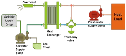
Control systems are essential for the safety and navigation efficiency of ships. Various control methods have been applied. A variable-speed control device that adjusts the voltage power frequency according to the freshwater (FW) temperature output from the central cooling system is applied to the cooling seawater (SW) pump motor to save energy. A typical central cooling system is shown in Figure 1.
The application of variable speed pumps to save electrical energy in ship central cooling systems has been researched extensively [1]-[4]. The application of variable speed motors to SW pumps [5] and the importance of using an integrated approach to reliably evaluate central cooling system retrofit solutions for variable speed SW pumps to maximize the fuel efficiency of ships have also been studied [6].
A data-based proportional-integral-derivative (PID) process controller was designed, and a variable-speed SW pump and controller were applied to an actual oil tanker; it was confirmed that the fuel consumption of the diesel generator was lower, compared with that of a constant-speed SW pump [7]. In addition, a feed-forward control method was applied [8]. The feedback position of the PI controller was changed to control the speed of the SW pump, and energy savings were confirmed through a simulation [9].
However, prior researchers focused on saving energy by using two controllers for the SW pump and a three-way valve, which are parts of the central cooling system. Applying the two controllers to a central cooling system requires proper tuning to achieve a good control performance with energy savings.
Therefore, a linear quadratic (LQ) controller was proposed in this study. First, a mathematical model was derived from the actual central cooling system. Then, the proposed LQ controller, which integrated two controllers for the central cooling system as a multi-input single-output system, was developed. It was used to prove the effective regulation of the FW output temperature through efficient control of the SW pump rotational speed and effective control of the three-way valve opening against step disturbances through simulations.
2. Mathematical Modeling of the Central Cooling System
A mathematical state–space model was required to develop the LQ controller. The modeling method was TY Jeon’s simulation model [9]. However, the developed mathematical state-space model applied two input variables: the electric voltage frequency of the SW pump and the opening of the three-way valve. This mathematical state–space model was linearized near the operating point. Table 1 lists the abbreviations used to derive the mathematical models.
2.1 Seawater Pump Modeling
The discharge amount (FC) of the SW pump is proportional to the rotational speed ω of the pump. The SW pump motor is an induction motor; therefore, it is linearized as shown in Equation (1)[10]-[12].
| (1) |
where kpv is the ratio of the change in the flow rate to the change in the pump rotational speed, fm is the input power frequency, and pm is the number of poles of the SW pump motor.
2.2 Three-way Valve Modeling
If the was Fhin and the opening volume to which the three-way valve opened toward the heat exchanger (HEX) was Ov, Ov had a value of 0 ≤ Ov ≤ 1. When Ov was zero, the valve was completely closed, the flow rate to the HEX became zero, and the flow rate bypassing the HEX reached a maximum. Conversely, when Ov = 1, it was fully open, the flow rate to the HEX reached a maximum, and the flow rate bypassing the HEX became zero. Therefore, the flow rate of the FW through the HEX (Fh) is as follows:
| (2) |
In contrast, the FW flow rate that bypassed the HEX (Fhby) can be described as shown in Equation (3) by applying Fhby instead of Fh and 1-Ov instead of Ov in Equation (2).
| (3) |
The FW outlet temperature of the three-way valve was the sum of the temperatures of Fh and Fhby by each flow rate. Therefore, the rate of change of the three-way valve outlet temperature can be expressed using Equation (4).
| (4) |
Where cph is the specific heat of FW, ρh is the density of FW, and m3wv is the mass of FW in the three-way valve.
2.3 Heat Exchanger Modeling
The temperature change rates of the SW and FW passing through the HEX can be expressed using Equations (5) and (6) [13]-[16].
| (5) |
| (6) |
2.4 Linearization of Modeling near the Operation Point
The mathematical model yielded by Equations (1) and (2) above were substituted into Equations (4), (5), and (6) and summarized in Equations (7), (8), and (9), respectively.
| (7) |
| (8) |
| (9) |
As shown in Equation (10), the SW pump motor power frequency fm and three-way valve opening degree Ov, which are the control inputs, were selected as the inputs u(t) of the central cooling system. As shown in Equation (11), the output variable and state variable x(t) selected the HEX outlet FW and SW temperatures Tho, Tco, and the three-way valve outlet FW temperature tout.
| (10) |
| (11) |
Finally, Equations (7), (8), and (9) for the central cooling system were linearized near the operating point and arranged in the form of a state-space equation, as in Equations (12) and (13) [17].
| (12) |
| (13) |
Matrices A, B, C, and D are given by Equations (14), (15), (16), and (17).
| (14) |
| (15) |
| (16) |
| (17) |
By substituting the parameters of the central cooling system in Table 2 into Equations (14) and (15), the system Equations (18) and (19) were obtained are as follows:
| (18) |
| (19) |
3. LQ Controller Development
If the optimal control vector for Equation (12) was equal to Equation (20),
| (20) |
a gain (K) that minimized the performance index(J) of Equation (21) was designed [18].
| (21) |
where Q is a positive-definite (or positive-semidefinite) Hermitian or real symmetric matrix, and R is a positive-definite Hermitian or real symmetric matrix. Matrices Q and R determine the relative importance of the error and expenditure of this energy, respectively.
In a central cooling system, the FW outlet temperatures of the three-way valve and HEX should be kept constant. Therefore, referring to Equation (11), the values of Matrix Q corresponding to Tho and tout were increased to 100 and 165, respectively, as shown in Equation (22). Matrix R was set as shown in Equation (23).
| (22) |
| (23) |
Equation (24) was obtained when Matrix K minimized the performance index J.
| (24) |
The control gain K was a 2 × 3 matrix. As shown in Figure 2, K1 was the SW pump power frequency, and u1 and K2 were connected to the opening input u2 of the three-way valve.
However, the developed mathematical model did not perfectly match the actual system. This implies that there is always an error. To eliminate this error, an integrator, which was 20% of K(2, 3) was added, as shown in Figure 2.
4. Simulation Results
The simulation test was conducted twice on a simulation model developed using MATLAB [9].
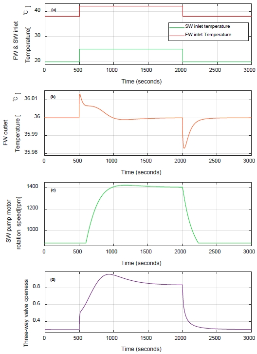
The first simulation was applied to the disturbance input. The FW and SW inlet temperatures were input as the step-up and step-down signals at 500s and 2000s, respectively, after the start of the simulation. The FW inlet temperature was input as 38°C, then 42°C, and finally 38°C, and the SW inlet temperature was input as 20°C, 25°C, and 20°C once again. After the step-up FW temperature was input, 25°C was maintained for 1500s.
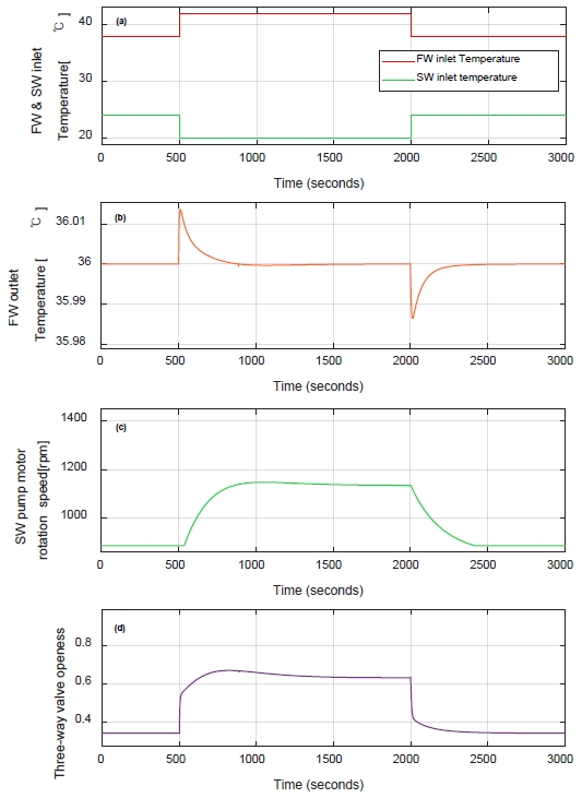
For the second simulation, the disturbance input was applied in the same manner as in the first. However, the SW inlet temperature was step-down input from 24°C to 20°C, then step-up input to 24°C again.
Through the simulation test, variations in the FW outlet temperature, SW pump rotational speed, and opening degree of the three-way valve were monitored and recorded to confirm the control performance.
The simulation results for the step-up and down disturbances of the FW and SW inlet temperatures are graphically represented in Figure 3 (a). Figure 3 (b) shows the variation in the FW output temperature. The overshoot was less than ±0.02℃. The settling time within ±0.01 ℃ was approximately 38s and 90s. As shown in Figure 3 (c), the rotational speed of the SW pump reached 1420 rpm and then decreased to 1403 rpm after the input of the step-up disturbance. The three-way valve opened to a maximum of 0.95 after the step-up disturbance, and then approached 0.83, as shown in Figure 3 (d).
Figure 4 shows the simulation results against the step input as per (a). The difference was that a step-down input of the SW inlet temperature preceded the step-up input. The overshoot was within ±0.02℃ as per the graph (b). Figure 4 (c) shows that the SW rotational speed increased to 1147 rpm and then settled at 1135 rpm. The three-way valve opened up to 0.67 and was fixed at 0.63.
5. Conclusion
The central cooling systemwas mathematically modeled to develop an LQ controller. The central cooling system modeled by the state–space equation was linearized near the operating point. Using a linearized model, a control gain K that minimized the performance index function J was obtained by assigning a state weight to the FW outlet temperatures of the HEX and three-way valve.
The developed LQ controller was applied to the simulation model to mitigate the step disturbance inputs of the FW and SW temperatures. The e of the LQ controller was validated through simulations. The FW outlet temperature was maintained at the desired value without significant overshoot, the SW pump rotational speed was efficiently controlled, and the three-way valve opening was effectively controlled. Thus, the good control performance of the integrated LQ controller developed in this study was established.
Author Contributions
Conceptualization, T. Jeon; Methodology, T. Jeon; Software, T. Jeon; Validation, T. Jeon; Formal Analysis, T. Jeon; Investigation, T. Jeon; Resources, T. Jeon; Data Curation, T. Jeon; Writing—Original Draft Preparation, T. Jeon; Writing—Review & Editing, T. Jeon; Visualization, T. Jeon.
References
- J. Oh, K. Jo, J. Kwak, S. Jin, J. Kim, and H. Lee, “A study on the energy saving system with the LabVIEW,” Proceedings of the Korean Society of Marine Engineers Conference, The Korean Society of Marine Engineering, pp. 250-251, 2005.
-
J. Lee, H. Yoo, Y. Kim, and J. Oh, “A study on the energy saving method by controlling capacity of sea water pump in central cooling system for vessel,” Journal of Advanced Marine Engineering and Technology, vol. 31, no. 5, pp. 592-598, 2007 (in Korean).
[https://doi.org/10.5916/jkosme.2007.31.5.592]

- Y. -H. Kim, “A study on suitable electric energy saving system for the cooling system of vessel,” Ph. D. Dissertation, Department of engineering, Korea Maritime & Ocean University, 2008.
-
Y. Kim, S. Bae, S. Jung, and J. Oh, “Study on the electric energy saving system in marine cooling system,” Journal of Advanced Marine Engineering and Technology, vol. 32, no. 8, pp. 1157-1163, 2008 (in Korean).
[https://doi.org/10.5916/jkosme.2008.32.8.1157]

- S. H. Hong, C. S. Kim, K. E. Hong, J. S. Oh, and J. U. Lee, “Application for RPM control of cooling sea water pump in central cooling system for ship,” Journal of the Korean Society of Marine Engineering, vol. 31, pp. 29-32, 2007.
-
E. G. Pariotis, T. C. Zannis, and J. S. Katsanis, “An integrated approach for the assessment of central cooling retrofit using variable speed drive pump in marine applications,” Journal of Marine Science and Engineering, vol. 7, no. 8, p. 253, 2019.
[https://doi.org/10.3390/jmse7080253]

-
S. V. Giannoutsos and S. N. Manias, “A data-driven process controller for energy-efficient variable-speed pump operation in the central cooling water system of marine vessels,” IEEE Transactions on Industrial Electronics, vol. 62, no. 1, pp. 587-598, 2014.
[https://doi.org/10.1109/TIE.2014.2317456]

-
C. Lee, T. Jeon, B. Jung, and Y. Lee, “Design of energy saving controllers for central cooling water systems,” Journal of Marine Science and Engineering, vol. 9, p. 513, 2021.
[https://doi.org/10.3390/jmse9050513]

-
T. Jeon, C. Lee, and J. Hur, “A study on the control solution of ship’s central fresh water-cooling system for efficient energy control based on merchant training ship,” Journal of Marine Science and Engineering, vol. 10, no. 5, p. 679, 2022.
[https://doi.org/10.3390/jmse10050679]

-
S. Chantasiriwan, “Performance of variable-speed centrifugal pump in pump system with static head,” International Journal of Power and Energy Systems, vol. 33, no. 1, pp. 15-21, 2013.
[https://doi.org/10.2316/Journal.203.2013.1.203-5073]

-
Y. Wang, H. Zhang, Z. Han, and X. Ni, “Optimization design of centrifugal pump flow control system based on adaptive control,” Processes, vol. 9, no. 9, p. 1538, 2021.
[https://doi.org/10.3390/pr9091538]

- T. Li, Q. Ren, and H. Zhao, “Research on optimal control of cooling water system in central air conditioning system,” 2013 Fourth International Conference on Intelligent Systems Design and Engineering Applications, pp. 511-514, 2013.
-
S. K. Al-Dawery, A. M. Alrahawi, and K. M. Al-Zobai, “Dynamic modeling and control of plate heat exchanger,” International Journal of Heat and Mass Transfer, vol. 55, no. 23-24, pp. 6873-6880, 2012. Available: https://www-sciencedirect-com.libproxy.kmou.ac.kr/science/article/pii/S001793101200525X, .
[https://doi.org/10.1016/j.ijheatmasstransfer.2012.06.094]

-
Y. Wang, S. You, W. Zheng, H. Zhang, X. Zheng, and Q. Miao, “State space model and robust control of plate heat exchanger for dynamic performance improvement,” Applied Thermal Engineering, vol. 128, pp. 1588-1604, 2018.
[https://doi.org/10.1016/j.applthermaleng.2017.09.120]

- I. Iu, N.A. Weber, P. Bansal, and D.E. Fisher, "DA-07-056 Applying the Effectiveness-NTU Method to Elemental Heat Exchanger Models", ASHRAE Transactions, vol. 113, no. 1, pp. 504-513, 2007.
-
D. M. Vega and H. G. Acevedo, “Advanced control system design for a plate heat exchanger,” 2020 IX International Congress of Mechatronics Engineering and Automation (CIIMA), pp. 1-6, 2020.
[https://doi.org/10.1109/CIIMA50553.2020.9290306]

- W.B. Bequette, Process control: modeling, design, and simulation, Prentice Hall PTR, 2003.
- K. Ogata, Modern control engineering, Fifth (International Edition) Edition, Upper Saddle River, NJ: Prentice Hall, 2009.


