Study of hydrodynamic analysis of eco-friendly buoys with biodegradable plastic materials
Copyright © The Korean Society of Marine Engineering
This is an Open Access article distributed under the terms of the Creative Commons Attribution Non-Commercial License (http://creativecommons.org/licenses/by-nc/3.0), which permits unrestricted non-commercial use, distribution, and reproduction in any medium, provided the original work is properly cited.
Abstract
The use of polystyrene (EPS) in ocean farming has recently changed to eco-friendly materials such as polyethylene (PE) and polypropylene (PP). However, despite this shift, PE and PP still contribute to microplastic generation owing to their vulnerability in marine environmental conditions and potential collisions with ships. Fragmented micro-plastics continue to occur due to the use of plastic materials without fundamental material conversion. Therefore, the development of an ocean farming buoys utilizing biodegradable materials such as polylactic acid (PLA) is in progress. As biodegradable materials have higher density than existing PPs and PEs, buoys crafted from PLA are heavier than those made from conventional materials. Accordingly, the buoys may sink and the buoyancy or productivity of farmed organisms may decrease. Therefore, in this study through hydrodynamic diffraction and response analysis, a weight of PP, PE, or PLA was applied to each buoy, and the kelp weight was assigned and compared to each buoy for analysis.
Keywords:
Eco-friendly buoys, Biodegradable plastic material, Microplastics, Finite element method, Hydrodynamic analysis1. Introduction
Recently, various studies have been conducted to reduce microplastics generated in the ocean [1][2]. Ocean farming has recently changed the usage of polystyrene (EPS) material (commonly known as Styrofoam) to an eco-friendly material composed of polyethylene PE and polypropylene PP [3]. However, PE and PP continue to generate microplastics due to ocean environmental conditions and ship collisions [4]. Fragmented microplastics persist due to the use of plastic materials without fundamental material conversion [5]. Therefore, the development of ocean farming buoys using biodegradable materials, such as polylactic acid (PLA), is in progress [6]. In contrast to existing PP and PE, biodegradable materials possess higher density, resulting in increased weight than existing buoys [7]. Consequently, the buoys may sink, decreasing the buoyancy or productivity of farmed organisms.
In this study, the suitability of the biodegradable buoy under development is reviewed by analyzing the wave motion characteristics of an existing buoy alongside the biodegradable variant.
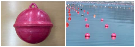
Figure 1 displays the developed biodegradable buoys and images depicting their actual installation in the sea. Biodegradable buoys exhibit similar shape as existing PE and PP buoys in appearance.
2. Model and analysis condition
2.1 Model
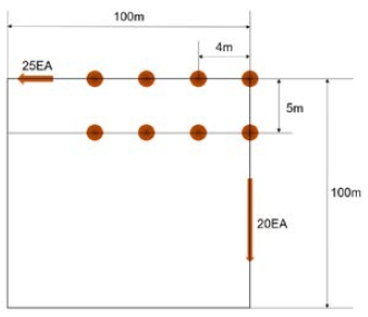
The focus of this study was a buoy designed for kelp farming. The aquaculture area measured 100 m × 100 m in width, accommodating a single row connected to 25 buoys horizontally, resulting in an approximate yield of 1.5 tons of kelp per row, as depicted in Figure 2. With twenty such rows installed vertically, the fish farm produced approximately 30 tons of kelp. Therefore, the weight of kelp per buoy is about 60 kg (1.5 tons/25 pieces = 60 kg).
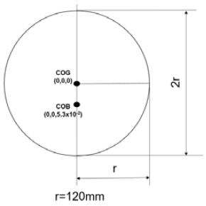
The basic specification of the target buoy is a sphere with a radius of 120 mm and a thickness of 2 mm, as shown in Figure 3.
Twenty-five horizontal directions were connected by strings, but each buoy was not completely constrained to perform six-degrees-of-freedom movements; therefore, in the horizontal direction, only four in the first and second rows were modeled.
A kelp weighing 60 kg was assigned to each buoy for analysis. The analysis was conducted by applying equal intervals between the buoys, spaced at 4 m horizontally and 5 m vertically. The model was utilized to review the interference and collision caused by horizontal and vertical buoyancy waves. The fish farm being studied was installed in the coastal sea and was secured with a rope to prevent it from floating away without using a separate mooring device. Therefore, the analysis was conducted by defining only the position such that it did not move by assigning boundary conditions without setting up a separate mooring device.
The PP, PE, and PLA models were analyzed according to their respective material properties, and each buoy was assigned a weight of PP 3.25 kg, PE 3.47 kg, and PLA 4.34 kg according to the physical properties. As mentioned above, it can be seen that PLA, a biodegradable material, weighs approximately 1 kg more than the existing PP and PE materials. Considering that approximately 500 buoys are installed throughout the fish farm, the total weight increased by approximately 500 kg. The densities and weights of each material are listed in Table 1.
2.2 Analysis Condition
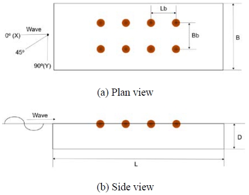
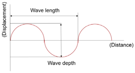
The ocean conditions for the hydrodynamic analysis were 50 m (L) × 50 m (B) × 10 m (D), as shown in Figure 4. As illustrated in Figure 5, wave conditions were simulated with a wave length, breadth, and period of 8.5 m, 0.7 m, and 5.7 s, respectively. The data was acquired from the Meteorological Data Opening Portal of the Meteorological Administration, specifically from Nohwa-do, Wando-gun, Jeollanam-do, which closely represents the actual buoy installation location.
In addition, three directions–0°, 45°, and 90°–were set, as shown in Figure 4 (b), and the floating characteristics of each material were reviewed. Hydrodynamic diffraction analysis was performed to review the characteristics of buoyancy according to ocean environmental conditions and to review the wave movement of buoyancy through hydrodynamic response analysis.
3. Hydrodynamic Analysis
3.1 Hydrodynamic Diffraction Analysis
Hydrodynamic diffraction analysis was performed using the ANSYS AQWA 2022R2 analysis software to review the wave motion in the buoy. Hydrodynamic diffraction analysis is based on the potential theory of Equation (1) [8].
| (1) |
Equation (1) denotes the Laplace equation, where the potential can be expressed as Equation (2), and the potential of the buoy represents the potential of the overlap.
| (2) |
In Equation (2), Φj represents the radiation potential Φω for buoy’s six degrees of freedom, and Φd represents the diffraction potential of the incident wave. Hydrodynamic diffraction analysis was performed using Equations (1) and (2): Two boundary conditions are applied: the pressure at the free surface of Equation (3) and the speed of wave motion at the seabed of Equation (4):
| (3) |
| (4) |
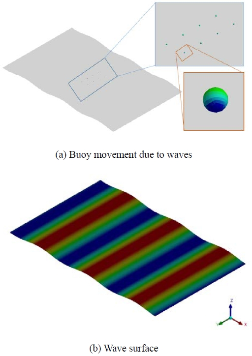
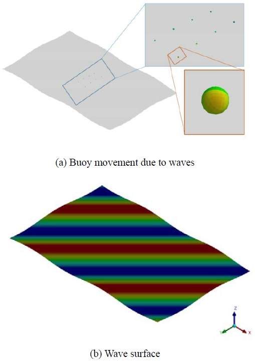
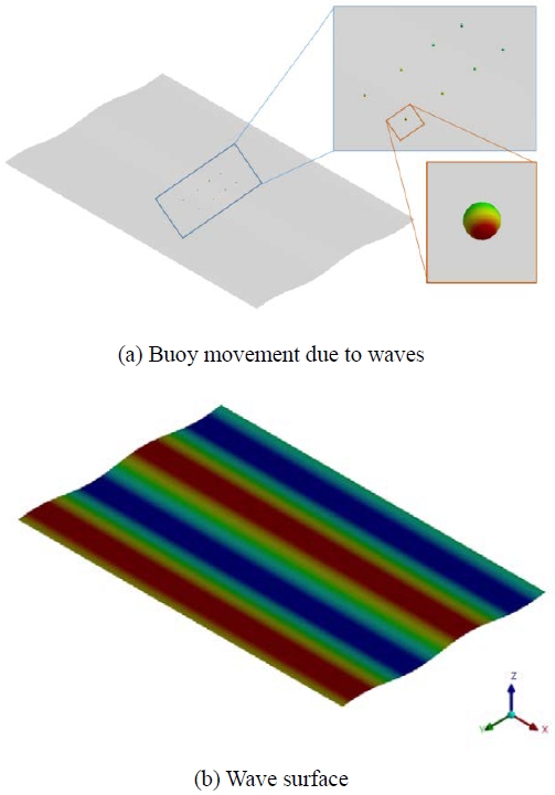
Figures 6-8 show the wave characteristics of the sea around the aquaculture buoy through hydrodynamic diffraction analysis according to the angle of incidence of the wave. Red and blue represents the rise and descent of the waves, respectively. Generally, floating bodies alter the flow of waves [9][10]; however, aquaculture buoys, being relatively small compared to the waves, tended to move in synchrony with the wave flow without significantly affecting it. The maximum wave height was 0.7 m, and it was confirmed that the load conditions were appropriately assigned. Figures 6-8 depict the results for 0°(X), 45°, and 90°(Y) directions, respectively. The figure subsection (a) demonstrates the movement of the buoy due to wave activity, and (b) represents the wave surface height at sea level.
3.2 Hydrodynamic Response Analysis
Hydrodynamic response analysis was performed based on the hydrodynamic diffraction analysis results. The analysis evaluated the wave motion characteristics at the center of gravity of the buoy for aquaculture, and the RAO of the buoy's response to the wave load was calculated using Equation (5).
| (5) |
In the equation, Ms, Mα, C, K, and F represent the structure mass, added mass, attenuation, hydrostatic stiffness, and incident load and diffraction load of the wave, respectively. The ocean environmental conditions used in the analysis was identical to those used in the hydrodynamic diffraction analysis.
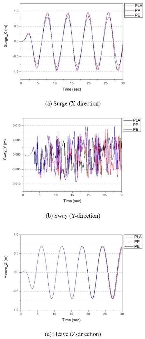
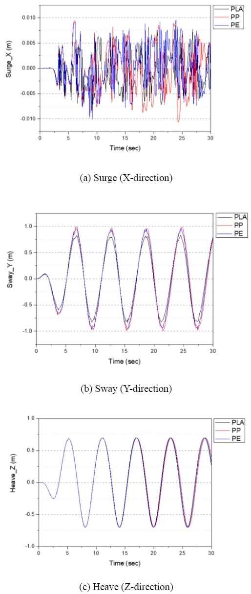
The interpretation was performed for 30 s. Figures 9-11 show the analysis results for three incident angles. A comparative graph was generated, illustrating the floating performance of the farming buoy in the X-, Y-, and Z-directions, categorized according to the material properties.
Thus, the hydrodynamic response analysis of the wave at 0°(X), PP, PE, and PLA were 0.975 m, 0.949 m, and 0.838 m, respectively, indicating wave movement in the surge (X) direction. In the sway (Y) direction, all three materials indicated minimal movement, with curves showing vibrations of less than 0.01 m. In the Heave (Z) direction, PP, PE, and PLA were 0.697 m, 0.698 m, and 0.699 m, respectively, depicting analysis results similar to a wave height of 0.7 m.
As a result of the hydrodynamic response analysis of the wave at 45°, PP, PE, and PLA were 0.708 m, 0.677 m, and 0.582 m, respectively, indicating waves movement in the Surge (X) direction. In the Sway (Y) direction, PP, PE, and PLA were 0.708 m, 0.677 m, and 0.582 m, respectively, which represents movement by waves. In the Heave (Z) direction, PP, PE, and PLA were 0.697 m, 0.698 m, and 0.699 m, respectively, depicting analysis results similar to a 0.7 m wave height. At 45°, movement occurred in X and Y, unlike at 0° and 90°.
As a result of the hydrodynamic response analysis of waves at 90° (Y), all three materials displayed graph curves indicating vibrations of less than 0.01 meters due to minimal wave movement in the Surge (X) direction. In the Sway (Y) direction, PP, PE, and PLA was 0.993 m, 0.962 m, and 0.833 m, respectively, representing the movement of waves. In the Heave (Z) direction, PP, PE, and PLA was 0.697 m, 0.698 m, and 0.699 m, showing analysis results similar to a wave height of 0.7 m.
As a result of the hydrodynamic response analysis of the three material properties, it was confirmed that the displacement of PLA, in the surge direction at 0° angle, the surge and sway direction at 45°, the sway direction at 90°, was about 0.1 to 0.15 m smaller than PP and PE. It was predicted that an increase in weight would result in decreased movement.
However, the analysis of the heave direction indicated a movement almost equivalent to the 0.7 m wave height, showcasing sufficient buoyancy to reflect the wave's movement characteristics. Therefore, despite the decrease in movement in the surge and sway directions due to increased weight, the floating performance of the buoy is expected to remain unaffected by this weight increase.
4. Conclusion
As a result of hydrodynamic analysis considering the marine environmental conditions of kelp farms and comparing PLA, a biodegradable material, with previously used materials, PP and PE, the following results were obtained:
- 1) First, the PP, PE, and PLA models were analyzed according to the material properties of the buoy. Each buoy was equipped with weights of PP, PE, and PLA, with individual kelp weights assigned for comprehensive examination. Ocean conditions for the hydrodynamic analysis were 50 ×50 × 10 m. Wave parameters, including a wavelength of 8.5 m, a wave depth of 0.7 m, and a wave period of 5.7 s, were applied to simulate conditions at the actual buoy installation site. Additionally, three directions (0°, 45°, and 90°) were set, and the floating characteristics of each material were reviewed.
- 2) Hydrodynamic diffraction analysis was conducted considering the incident angle of the waves. Generally, floating bodies change the flow of waves; however, aquaculture buoys, being relatively diminutive structures in comparison to waves, exhibit movement concurrent with the flow of waves without significantly affecting them.
- 3) Based on the hydrodynamic response analysis of the three material properties, it was confirmed that the displacement of PLA was smaller than that of PP and PE. However, when looking at the analysis results for the heave direction, it was confirmed that it had almost the same value as the wave height. Sufficient buoyancy was ensured to demonstrate wave movement characteristics. Therefore, despite increased weight, the aquaculture buoy's floating performance is anticipated to remain unaffected.
- 4) In the further research, buoys will be installed in actual fish farms to review the floating performance of buoys applied with biodegradable materials will be conducted through simulation comparison of results.
Acknowledgments
This research is the result of Rural and fishing village Problem-Solving Support Project ‘Development of eco-friendly buoys for fish-farming using biodegradable plastic materials’ funded by Jeonnam Technopark, Korea.
Author Contributions
Conceptualization, J. S. Jo; Methodology, J. S. Jo; Software,J. S. Jo; Validation, J. S. Jo; Formal Analysis, J. S. Jo; Investigation, J. S. Jo; Resources, J. S. Jo; Data Curation, J. S. Jo; Writing—Original Draft Preparation, J. S. Jo; Writing—Review & Editing, J. S. Jo.
References
-
M. Jang, W. -J. Sim, G. -M. Han, M. Rani, Y. -K. Song, and S. -H. Hong, “Widespread detection of a brominated flame retardant, hexabromocyclododecane, in expanded polystyrene marine debris and microplastics from South Korea and the Asia-Pacific coastal region,” Environmental Pollution, vol. 231, part. 1, pp. 785-794, 2017.
[https://doi.org/10.1016/j.envpol.2017.08.066]

- K. -S. Kim, “A study on Domestic Implementation of G20 Action Plan on Marine Litter,” The Korean Association of Ocean Science and Technology Societies, pp. 87, 2018 (in Korean).
- T. -H. Yoon, J. -W. Hong, J. -S. Hwang, J. -S. Kim, J. -S. Kim, and H. -Y. Kim, “FE analysis validation of three-point bending test about grazing treatment effect in outer surface of EPP hollowed buoy,” ICIC Express Letters Part B: Applications, vol. 9, no. 6, pp. 515-523, 2018.
-
S. -M. Kim, S. -H. Back, Y. -S. Han, T. Davaadorj, B. -H. Go, and H. -S. Jeon, “Current research trends for treatment of microplastics,” Journal of Korean Institution of Resources Recycling, vol. 29, no. 5, pp. 15-17, 2020 (in Korean).
[https://doi.org/10.7844/kirr.2020.29.5.15]

- S. -M. Kim, H. -I. Lee, H. -S. Jeong, and Y. -J. Jeon, “Recent trends in the production of Polyhydroxyalkanoates using marine microorganisms,” Journal of Life Science, vol. 33, no. 8, pp. 680-691, 2023 (in Korean).
-
J. -S. Jo, J. -S. Kim, and S. -J. Choi, “Evaluation of impact resistance and material properties of eco-friendly buoys with biodegradable plastic materials,” Journal of Advanced Marine Engineering and Technology, vol. 46, no. 5, pp. 230-236, 2022.
[https://doi.org/10.5916/jamet.2022.46.5.230]

-
L. Suarez, Z. Ortega, F. Romero, R. Paz, and M. -D. Marrero, “Influence of giant reed fibers on mechanical, thermal, and disintegration behavior of rotomolded PLA and PE composites,” Journal of Polymers and the Environment, vol. 30, pp. 4848-4862, 2022.
[https://doi.org/10.1007/s10924-022-02542-x]

- ANSYS, ANSYS AQWA User's manual, 2010.
- D. -H. Lee and J. -Y. Jeong, “Integrated analysis of hydrodynamic motions and structural behavior of large-scaled floating structures using AQWA-ANSYS coupling,” The Korean Society of Automotive Engineers, vol. 24, no. 6, pp. 601-608, 2011 (in Korean).
-
Y. -C. Oh, O. -S. Gim, and J. -Y. Ko, “Hydrodynamic-structural response coupling analysis to a rectangle floating structures,” Journal of the Korean Society of Marine Environment & Safety, vol. 18, no. 6, pp. 577-583, 2012 (in Korean).
[https://doi.org/10.7837/kosomes.2012.18.6.577]


