A study on carbon dioxide emissions reduction in marine diesel engines using a chemical carbon absorber
Copyright © The Korean Society of Marine Engineering
This is an Open Access article distributed under the terms of the Creative Commons Attribution Non-Commercial License (http://creativecommons.org/licenses/by-nc/3.0), which permits unrestricted non-commercial use, distribution, and reproduction in any medium, provided the original work is properly cited.
Abstract
The shipping industry is responsible for a considerable portion of global carbon dioxide (CO2) emissions, and reducing these emissions is crucial to mitigate the impacts of climate change. In this study, a chemical carbon absorber (CCA) was used to reduce CO2 emissions from marine diesel engines, and an experiment was performed to determine the efficiency of the method and quantify the reduction achieved. The experiment consisted of injecting 30% and 100% of aqueous CCA into the exhaust gas pipeline via the nozzle of a selective catalytic reduction system. The CO2 concentration in the exhaust gas before and after the CCA injection point was measured to monitor the CO2 emission reduction. The results showed that using CCA can reduce CO2 emissions from the exhaust gas of marine diesel engines. However, further research is needed to optimize the process and improve its efficiency. Three potential areas for future research include installing reductions within the exhaust pipe to increase reaction contact time, recycling waste heat energy from the engine to increase reaction temperature, and improving mixing units to enhance reaction efficiency at higher engine loads. Overall, the results of this study confirm that using CCA technology can reduce CO2 emissions from marine diesel engine.
Keywords:
CO2 capture, Marine diesel engines, KOH based metal, Selective catalytic reduction, Carbon capture absorber1. Introduction
Global warming and climate change have become a global issue, leading to various problems such as rising of sea levels, more frequent and severe extreme weather events, and risks to biodiversity and human health. The international community has recognized the gravity of the situation and taken efforts to improve it. Despite the growing concerns, annual emissions from the shipping industry are close to 1 billion tons of carbon dioxide (CO2), representing approximately 3% of global emissions [1], and continue to increase owing to the rising demand for maritime trade, with projections indicating that emissions will reach 2–3 billion tons by 2050 [2]. To address this issue, the international maritime organization (IMO) has established targets to reduce 40% of CO2 emissions by 2030 and reach net zero greenhouse gas emissions by 2050, in comparison to 2008 levels, in which international shipping was responsible for emitting 794 million tons of CO2 [3]-[5]. As the engines of ships are the primary source of CO2 emissions in shipping industries, the application of CO2 capture technology to marine diesel engines has emerged as a viable solution.
CO2 capture technology has already been effectively employed in various industries, such as power plants, and has been found to considerably reduce CO2 emissions from marine diesel engines. The integration of CO2 capture technology into marine diesel engines is critical for the long-term sustainability and profitability of the industry, particularly under the pressure of IMO regulations like the energy efficiency existing ship index [6] and carbon intensity indicator [7]. Furthermore, considering the increasing public demand for a sustainable shipping industry, companies that do not achieve CO2 emission reductions are expected to eventually lose space in the market. To address these challenges, this study aimed to perform an applied test employing a chemical carbon absorber (CCA) for the exhaust gas of ship internal combustion engines. The three primary CO2 capture systems for commercial use encompasspre-combustion, oxy-fuel combustion, and post-combustion methods [8]-[10]. Among these, post-combustion CO2 capture is the preferred industrial system, as it can treat substantial flue gas volumes and serves as an appealing end-of-pipe solution [9]-[11]. In this experiment the post-combustion method was implemented using the selective catalytic reduction (SCR) equipment, which is already installed on existing commercial ships, to confirm whether SCR components including injection nozzle and dosing unit can be utilized.
In this experiment, CCA was injected in concentrations of 30% and 100% into the exhaust gas pipeline through SCR nozzles to confirm the efficiency of CO2 absorption by the reaction of CCA with exhaust gases. To monitor CO2 emissions, the emission rate of CO2 in the exhaust gas before and after the CCA injection point was measured. The CO2 emission reduction rate was determined and the amount of CO2 emission was quantified.
This experiment enabled to verify the potential of using CO2 capture technology in shipping industries [12].
2. Overall system description
2.1 Marine diesel engine
The experiment was conducted under the following conditions. The experiment was aimed to confirm the actual reduction rate of CO2 by applying CCA to commercially used engines for maritime shipping. CCA, selected as the experiment subject, is an aqueous solution capable of reducing CO2 by trapping and converting it into sodium carbonate or potassium carbonate, as described in the following chemical reactions [13].
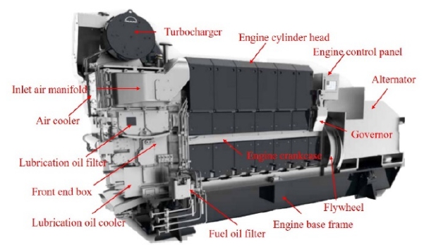
The marine diesel engine used in the experiment was an STX-MAN engine (6 cylinder, in-line type), as shown Figure 1, which is mainly used in cargo ships, tankers, Ro-ro vessels, and tug-boats. This engine can use multiple types of fuel including marine gas oil, marine diesel oil, and heavy fuel oil, and it emits approximately 100 tons of exhaust gas per hour. The specifications of the diesel engine and fuel are listed in Table 1 [14].
2.2 Measurement of CO2 capture ratio
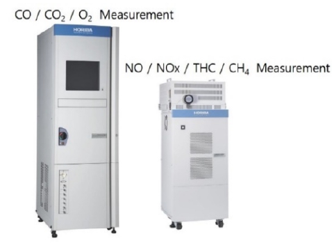
Horiba MEXA (Figure 2), a widely used measurement tool in the maritime field, was selected for the analysis of exhaust gas emissions. The equipment was used to measure the carbon ratio in the generated exhaust gas. The substances measured from the exhaust gas are NOx, CO2, O2, and total hydrocarbons (THC) [15]. Based on the measurement results, the influence of other environmental pollutants in addition to CO2 can be confirmed.
2.3 Measuring and injection equipment
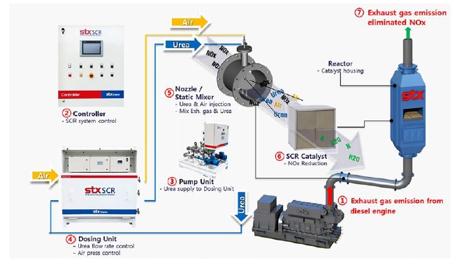
Many ships have SCR systems installed to reduce NOx emissions considering environmental factors. The principle of SCR systems to reduce NOx is the chemical reaction between urea/catalyst and NOx in the exhaust gas to change from NOx to Nx and H2O. The STX-SCR system consists of SCR controller, pump unit, dosing unit, mixer, nozzle, catalyst, and reactor, as shown in Figure 3. The SCR operation sequence is as follows:
①Exhaust gas emission from engine → ② SCR controller→ ③ Pump unit → ④ Dosing unit → ⑤ Nozzle & mixer → ⑥ Catalyst → ⑦ Elimination of NOx from the emission exhaust gas
⑤step in Figure 3 is the chemical reaction to produce ammonia from N, N2 in the exhaust gas as follows [16]:
(NH2)2CO → (NH2)2CO (s) + H2O
(NH2)2CO → NH3 (g) + HNCO
HNCO (g) + H2O → NH3 (g) + CO2
⑥step in Figure 3 is the chemical reaction to produce Nx,H2O from ammonia as follows [16]:
4NO + 4HN3 + O2 → 4N2 + 6H2O
2NO + 2NO2 + 4NH3 → 4N2 + 6H2O
2NO2 + 4NH3 + O2 → 3N2 + 6H2O
Through steps ⑤ and ⑥, NOx becomes Nx and H2O. Exhaust gas analysis (utilizing MEXA equipment in Figure 2 is conducted in step ⑦ to confirm NOx elimination from the exhaust gas.
For this experiment, the STX-SCR system in Figure 3 was installed with STX-MAN diesel engine and urea was replaced by CCA to confirm the CO2 capture rate. The reactor was also replaced by a straight pipe 500 A, as a catalyst was not required, and utilized for NOx reduction.
The applicability of the nozzle for injecting urea and the dosing unit in SCR systems for controlling the injection amount were also examined. Two types of flow meter of the dosing unit were evaluated: electromagnetic type and gear type, whose specifications are listed in Table 2. These two types of flow meter were sequentially installed in the dosing unit to check the conductivity of the fluid and confirm the flow detection range. The experiment results indicated that the gear type had a measurement range of 0.1–50.0 L/h, whereas the electromagnetic type had a measurement range of 30.0–120 L/h. Therefore, the electromagnetic type flow meter was selected as the experiment equipment to be installed in the existing dosing unit.
The expected CCA (Concentration: 100% and 30%) consumption at each engine load, as described in Table 3, was calculated assuming a CO2 capture amount of 30%. The spray condition was not an issue.
Equations (1) and (2) represent the calculation formulas for consuming 100% and 30% CCA, respectively.
| (1) |
Equation (1) was used to calculate the expected CCA consumption rate considering a CO2 emission reduction from exhaust gas of 30% when the CCA was diluted to 100%. The non-dimensional conversion factor, Cf [17], is the ratio of the fuel consumption [g] and CO2 emission [g] based on the carbon content of the fuel. In this case, the Cf had a value of 3.151040. Based on the result of the experiment, the CCA consumption rate was estimated to be 15% when CO2 emissions in the exhaust gas were reduced by 30%. Thus, the expected CCA consumption rate to CO2 emission reduction was calculated by multiplying the fuel consumption by 15%. The final CCA consumption rate was estimated by applying the CCA flow uniformity coefficient of 1.1, which is a factor that accounts for the uneven distribution of CCA in the exhaust gas.
| (2) |
Equation (2) was used to calculate the expected CCA consumption rate to a CO2 emission reduction from the exhaust gas of 30% when the CCA was diluted to 30%. The non-dimensional conversion factor, Cf, was the ratio of the fuel consumption [g] and CO2 emission [g], based on the carbon content of the fuel. In this case, Cf had a value of 3.151040. Previous Equation (1) indicated that the CCA consumption rate was estimated to be 15% when CO2 emissions in the exhaust gas were reduced by 30%, based on the result of the experiment. Equation (2) is different from Equation (1) in that it considers the dynamic viscosity of CCA (9.4 mPa.s). This means that to achieve the same effect of reducing CO2 by 15%, 2.9256 times more diluted CCA must be injected. The expected CCA consumption rate to CO2 emission reduction was calculated by multiplying the CCA consumption rate (15%). The final CCA consumption rate was estimated by applying the CCA flow uniformity coefficient of 1.1.
The selection of the flow meter was based on a thorough assessment of the available range of flow supply, calculated CCA consumption rate in Table 3, CCA viscosity, and visual inspection of the spray state.
Furthermore, the experiment was conducted considering the flow allowance range of the existing SCR equipment utilized for NOx reduction. The maximum detection range of the electro-magnetic flowmeter considering the error tolerance (±2%) confirmed that it can be applied to an engine load of up to 10%. Consequently, the CO2 capture experiment was conducted with a maximum engine load set at 10%.
2.4 Experimental diesel engine configuration
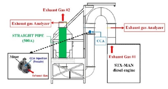
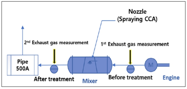
The configuration of the experiment system was same as that of the pre-existing SCR system installed in ships. This system configuration consists of engine, pipe lines, mixer, nozzle, and exhaust gas analyzer, as shown in Figure 4.
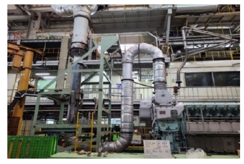
The actual experiment facility, assembled engine, and SCR unit excluding the reactor are shown in Figure 5. Figure 6 shows the simplified flow for the CO2 capture system in this experiment, indicating the exhaust gas flow and measuring locations before and after CCA injection. The exhaust gas coming from the engine first traverses an exhaust duct, wherein the CO2 content under-goes initial analysis (referred to as 'Exhaust Gas #1' in Figure 4).
The value derived from this analysis serves as the reference for emissions. Subsequently, the exhaust gas is directed through a mixer. Despite inducing an increase in back pressure, the mixer ensures uniform distribution within the exhaust pipe, facilitating the required chemical reactions. Upon the atomization of the CCA in a vaporized state via a nozzle within the mixer, the CO2 capture process is initiated. In sequence, the exhaust gas passes through a 500A pipe before being expelled externally. Prior to this discharge, the CO2 content undergoes a secondary analysis (referred to as 'Exhaust Gas #2' in Figure 4) within the mixer. The CO2 capture rate is determined by comparing the primary and secondary analyses values.
3. Experimental conditions and results
3.1 Experiment conditions to measure CO2 capture rate
The first experiment, as detailed in Table 4, was designed to measure the amount of CO2 captured by the system under different injection amounts of 100% CCA and 30% CCA. During this experiment, the engine was maintained at a load of 0% and the amount of CCA injected into the system was gradually increased. The conditions were set to confirm the CO2 capture rate according to the change in the amount of CCA.
The second experiment, as detailed in Table 5, was conducted to measure the amount of CO2 captured when a fixed amount of CCA was injected under gradually increasing engine load conditions up to 10%. The conditions were set to confirm the CO2 capture rate according to the change in the load condition from 0% to 5% and to 10%.
3.2 Experiment result of CO2 reduction
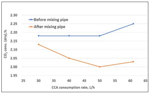
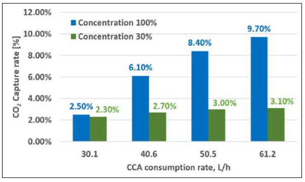
The first experiment shown in Figure 7 was conducted to measure the CO2 capture rate at no load. Case 1 refers to the application of CCA in a concentration of 100% and measurement of the CO2 emission before and after the mixing pipe.
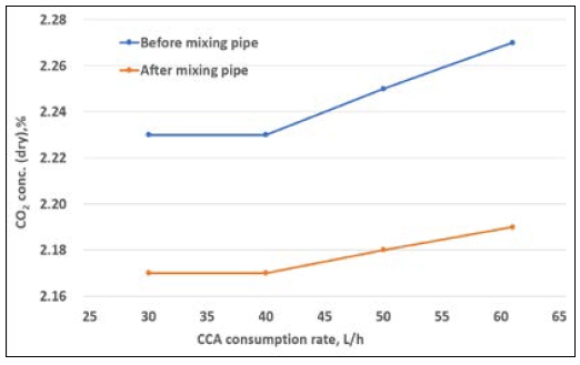
The CO2 capture rate was gradually increased with the increase of the CCA injection amount from 31.0 L/h to 61.2 L/h. As shown in Figure 7, the CO2 emission decreased as the injection volume increased. Case 2 refers to the application of CCA in a concentration of 30% and measurement of the CO2 emission before and after the mixing pipe. As observed in Figure 8, the CO2 capture rate did not considerably change even when the injection quantity increased from 30.1 L/h to 61.2 L/h.
Table 6 lists the CO2 capture rates when the injection amount for each CCA concentration tested (case 1 – 100% and case2 – 30%) was changed at a fixed load. The CO2 capture rate in case 1 gradually increased up to 9.7%, whereas that in case 2 did not considerably improve. Figure 9 shows that the carbon capture rate increased as the CCA injection rate increased under 0% engine load with relatively low exhaust gas volume. In addition, considering CCA concentrations of 100% and 30% (CCA diluted in water), the CO2 capture rate relatively increased as the CCA injection rate increased for a concentration of 100%, whereas it slightly changed for a concentration of 30%. This means that the CCA concentration and injection amount are important factors to obtain better CO2 capture efficiency. Based on these results, the CCA injection amount and concentration are key factors for achieving an optimized CO2 capture rate in future investigations or experiments. To further enhance the CO2 capture efficiency, a pumping control system in the dosing unit could be implemented. This system could utilize a proportional–integral–derivative control with a feedback mechanism to optimize the injection process.
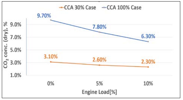
Cases 3 and 4 in Table 7 were expanded from Cases 1 and 2, respectively. Experiments were conducted on CO2 reduction by sequentially increasing the load to 0%, 5%, and 10%. Figure 10 is a schematic of the CO2 reduction amount, confirming that the reduction amount depends on the load.
As shown in Figure 11, the CO2 capture rate was higher for 100% CCA compared to the case with 30% CCA for all engine loads tested. Based on the experiment results, as the engine load increased, the exhaust gas volume increased proportionately.
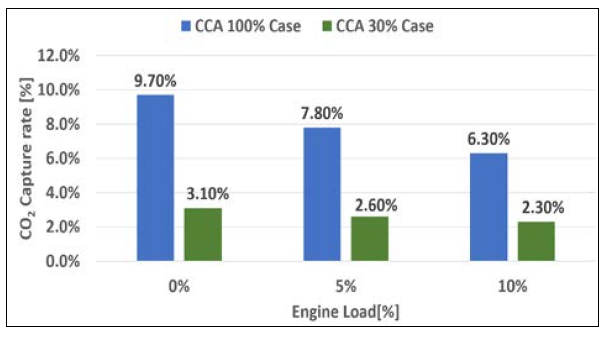
CO2 capture efficiency according to engine load (0%, 5%, and 10%) and CCA concentration (100% and 30%)
Therefore, a larger injection volume is required to achieve an optimal CO2 capture efficiency. Additionally, a higher CO2 capture rate can be expected as the CCA concentration increases.
4. Conclusion
In this study, CCA was investigated as a CO2 capture agent for the exhaust gas of a marine diesel engine. The experiment was conducted under conditions that closely resemble those of a currently operating engine of a ship, without the use of additional devices or equipment to increase CO2 capture.
The results indicated that the CO2 capture rate increased as the CCA concentration and injection flow rate increased. The maximum capture rate achieved using 100% concentration of CCA was 9.7% at 0% load, 7.8% at 5% engine load, and 6.3% at 10% engine load. However, the results also indicated that the reaction time between CCA and the exhaust gas decreased as the engine load increased, leading to a decrease in CO2 capture efficiency.
By addressing these study areas, the CO2 capture efficiency of marine diesel engines could be improved, contributing to reducing greenhouse gas emissions from shipping.
Future research can include improving the mixing unit to extend the reaction time for more efficient reactions between exhaust gas and CCA at higher engine loads. It could also include research on capturing the chemical reaction products of CCA, such as potassium carbonate and H2O, and using them as ballast water or desiccants on ships.
Acknowledgments
Author Contributions
Conceptualization, K. S. Ko; Methodology, Y. G. An; Formal Analysis, Y. G. An; Investigation, K. S. Ko; Resources, Y. G. An; Data Curation Y. G. An; Writing-Original Draft Preparation, K. S. Ko; Writing-Review & Editing, Y. D. Son; Visualization, Y. G. An; Supervision, Y. D. Son.
References
- C. Lo, Onboard carbon capture: dream or reality, Ship Technology, April 24, 2013. [Online]. Available: https://www.ship-technology.com/features/featureonboard-carbon-capture-dream-or-reality/, .
-
N. V. D. Long, D. Y. Lee, C. Y. Kwag, Y. M. Lee, S. W. Lee, V. Hessel, and M. Y. Lee, “Improvement of marine carbon capture onboard diesel fueled ships,” Chemical Engineering and Processing-Process Intensification, vol. 168, 2021. [Online]. Available: https://doi.org/10.1016/j.cep.2021.108535.
[https://doi.org/10.1016/j.cep.2021.108535]

- International Marine Organization, Greenhous gas study, Forth IMO GHG Study 2021, 2021. [Online]. Available: https://nextgen.imo.org/news/28, .
- IEA, World Energy outlook 2022, International Energy Agency, 2022. [Online]. Available: https://www.iea.org/reports/world-energy-outlook-2022, .
- International Maritime Organization, 2023 IMO strategy on reduction of GHG emissions from Ships, 7 July 2023. [Online]. Available: https://www.imo.org/en/MediaCentre/MeetingSummaries/Pages/MEPC-80.aspx, .
- International Maritime Organization, “2021 guidelines on survey and certification of the attained Energy Efficiency Existing Ship Index(eexi)”, June 17, UK, 2021.
- C. Bryan, Including estimates of black carbon emissions in the Fourth IMO GHG Study, International Council of Clean Transportation (ICCT), March, 2019.
-
T. A. Adams, L. Hoseinzade, P. B. Madabhushi, and I. J. Okeke, “Comparison of CO2 capture approaches for fossil-based power generation: Review and meta-study,” Processes, vol. 5, no. 3, p. 44, 2017. [Online]. Available: https://doi.org/10.3390/pr5030044.
[https://doi.org/10.3390/pr5030044]

-
D. Y. C. Leung, G. Caramanna, and M. Mercedes Maroto-Valer, “An overview of current status of carbon dioxide capture and storage technologies,” Renewable and Sustainable Energy Reviews, vol. 39, pp. 426-443, 2014. [Online]. Available: https://doi.org/10.1016/j.rser.2014.07.093.
[https://doi.org/10.1016/j.rser.2014.07.093]

-
M. Kanniche, R. Gros-Bonnivard, P. Jaud, J. Valle-Marcos, J. Amann, and C. Bouallou, “Pre-combustion, post-combustion and oxy-combustion in thermal power plant for CO2 capture,” Applied Thermal Engineering, vol 30, no. 1, pp. 53-62, 2010. [Online]. Available: https://doi.org/10.1016/j.applthermaleng.2009.05.005.
[https://doi.org/10.1016/j.applthermaleng.2009.05.005]

-
P. Mores, N. Rodríguez, N. Scenna, and S. Mussati, “CO2 capture in power plants: Minimization of the investment and operating cost of the post-combustion process using MEA aqueous solution,” International Journal of Greenhouse Gas Control, vol. 10, pp. 148-163, 2012. [Online]. Available: https://doi.org/10.1016/j.ijggc.2012.06.002.
[https://doi.org/10.1016/j.ijggc.2012.06.002]

-
L. Yang, J. Heinlein, C. Hua, R. Gao, S. Hu, L. Pfefferle, and Y. He, “Emerging dual-functional 2D transition metal oxides for carbon capture and utilization: A review,” Fuel, vol 324, Part B, 2022. [Online]. Available: https://doi.org/10.1016/j.fuel.2022.124706.
[https://doi.org/10.1016/j.fuel.2022.124706]

-
F. Isa, H. Zabiri, N. K. S. Ng, A. M. Shariff, “CO2 removal via promoted potassium carbonate: A review on modeling and simulation techniques,” International Journal of Green-house Gas Control, vol. 76, pp. 236-265, 2018. [Online]. Available: https://doi.org/10.1016/j.ijggc.2018.07.004.
[https://doi.org/10.1016/j.ijggc.2018.07.004]

- MAN Energy Solution, Project Guide - Marine Four-stroke GenSet compliant with IMO Tier Ⅱ, MAN-Diesel & Turbo, 2015.
-
IMO Organization, MEPC 70/18/Add.1, Annex 9, IMO, 2016.
[https://doi.org/10.1007/978-3-476-05431-9_1]

-
L. Wei, H. Zhang, C. Sun, and F. Yan, “Simultaneous estimation of ammonia injection rate and state of diesel urea-SCR system based on high gain observer,” ISA Transactions, vol. 126, pp. 679-690, 2022. [Online]. Available: https://doi.org/10.1016/j.isatra.2021.08.002.
[https://doi.org/10.1016/j.isatra.2021.08.002]

-
S. H. Jeong, H. M. Kim, H. J. Kim, O. H. Kwon, E. Y. Park, E. Y. Kim, and J. H. Kang, “Predictions of the reduction of exhaust gas on an Urea-SCR system according to the injection direction,” Transactions of the Korean Society of Automotive Engineers, vol. 29, no. 1, pp. 67-73, 2021 (in Korean).
[https://doi.org/10.7467/KSAE.2021.29.1.067]


