Performance analysis in water-gas shift reactor for hydrogen yield improvement
Copyright © The Korean Society of Marine Engineering
This is an Open Access article distributed under the terms of the Creative Commons Attribution Non-Commercial License (http://creativecommons.org/licenses/by-nc/3.0), which permits unrestricted non-commercial use, distribution, and reproduction in any medium, provided the original work is properly cited.
Abstract
This study aimed to produce hydrogen using unused natural gas generated from the fuel storage tank of a liquefied natural gas-powered ship. As natural gas and steam pass through steam–methane reforming (SMR) and water-gas shift (WGS) reactors, carbon monoxide, carbon dioxide, and reformed gases such as hydrogen are produced. In particular, carbon monoxide produced in an SMR reactor reacts with steam while passing through a WGS to increase the production of hydrogen and its conversion to carbon dioxide. In this study, the carbon monoxide–steam reaction mechanism occurring in a WGS reactor was analyzed, and performance variations in the WGS reactor were investigated through changes in variables, such as temperature and pressure. During the WGS reaction, as the temperature decreased, the conversion rate of carbon monoxide (WCO) increased, regardless of pressure. As the amount of carbon monoxide decreased, the conversion rate of carbon dioxide (WCO2) increased.
Keywords:
Boil-off gas, Fuel cell, Hydrogen production, Steam–methane reforming, Water-gas shift1. Introduction
The world is aware of the seriousness of environmental pollution, such as air and water pollution, resource wastage, global warming, and climate change, caused by the indiscriminate use of coal fuels. Efforts have been made to reduce the emission of environmental pollutants by measuring the amount of carbon dioxide emitted and offsetting it to revive nature using clean energy, such as solar and wind power, or by using new and renewable energy.
The Paris Agreement, a system in which both developed and developing countries can participate, was agreed upon to replace the Kyoto Protocol, which expired in 2020. Efforts are being pursued to maintain the global average temperature rise, which is significantly lower than 2 ℃, compared to before industrialization and to limit it to 1.5 ℃ or lower. Energy conversion for decarbonization is essential because a global stock-take is being conducted to evaluate the possibility of implementing the Paris Agreement and achieving long-term goals every five years from 2023 [1][2]. Hydrogen, an ecofriendly energy source that can replace petroleum and coal, is a clean energy source that does not emit greenhouse gases. Researchers in various fields have actively investigated hydrogen as a clean energy source [3][4].
Hydrogen production methods include steam reforming of natural gas, utilization of by-product hydrogen, and water electrolysis using renewable energy [5]. Currently, most hydrogen is produced using a natural-gas-reforming method that extracts hydrogen from natural gas composed of carbon and hydrogen using high-temperature steam generated from coal fuels [6].
In vessels, it is difficult to use clean energy to reduce environmental pollution and to supply and demand clean energy for stable green hydrogen production [7]. Therefore, it is advantageous to apply a technology capable of capturing carbon dioxide through a carbon capture system (CCS) using a blue hydrogen generation method.
Wang et al. [7] conducted an experiment on the methane–steam-reforming reaction in a microchannel catalyzed by Wang et al. Cheon et al. [8] examined the properties of a methanol–steam reformer using the latent heat of steam. Lee [9] conducted various studies on steam reforming, such as analyzing the characteristics of a reformer to apply a hydrogen-fue cell system to a liquefied natural gas (LNG)-powered ship.
The purpose of this study is to install a water–gas shift (WGS) reactor after the reforming reaction in a steam-methane reforming reactor (SMR) and vary the temperature and pressure of the SMR and WGS reactors, which are variables of the transition reaction, in various ways to generate hydrogen. This study attempts to determine the best approach to improve H2 yield.
2. Methane–steam reforming process
Methane–steam reforming is a process in which forward and reverse reactions occurs. SMRs, WGSs, and direct steam reforming cause chemical reactions with reactants on the catalyst surface.
The reforming process involves the production of hydrogen through a chemical reaction between methane and steam and is called steam–methane reforming. This reaction primarily uses LNG, a representative hydrocarbon, and the number of moles of gas increases, corresponding to an endothermic process. Water gas generated during the reaction inside the SMR is introduced into the WGS reactor. The water gas generated in the reformer with a high carbon monoxide generation rate is converted into carbon dioxide and hydrogen through a water-gas shift reaction because the generation rate of carbon monoxide is higher than that of hydrogen. That is, the water-gas shift reaction, which can reduce catalyst poisoning attributed to CO and produce additional hydrogen gas during the SMR, is accompanied by the conversion of carbon dioxide, which corresponds to an exothermic process.
Carbon accumulates on the surface of the catalyst by the CO generated during the SMR, resulting in a rapid decrease in catalyst activity. Coke formation and carbon deposition occur, resulting in decreased hydrogen production efficiency.
The use of a catalyst is essential in facilitating the above methane-steam reforming reaction. The chemical formula for the main thermodynamic and kinetic reactions of the steamme-thane-reforming reaction on the catalyst surface during the reforming process is as follows [10].
r1: Steam-Methane reforming reaction
| (1) |
r2: Water gas shift reaction
| (2) |
r3: Direct steam reforming reaction
| (3) |
These three chemical reactions produce and reduce methane (CH4), carbon monoxide (CO), carbon dioxide (CO2), and hydrogen (H2). Each reaction is reversible, and the equilibriums of the SMR and WGS reactions are determined with respect to the temperature, pressure, and reactant concentration, which affect the progress of the reaction [11].
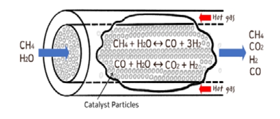
Figure 1 shows the mechanism of the reforming reaction and the chemical transition process of the WGS reaction occurring in the SMR. Methane and water vapor are mixed and introduced into the SMR, and the catalysts inside the SMR facilitate the chemical reaction in which hydrogen is synthesized.
Various types of catalysts are used in the reforming reactions; however, Ni/Al2O3 catalysts are widely used because of their low cost and high activity [12][13].
The details of the major reaction mechanisms occurring in the reformer and its design can be found in Lim et al. [14].
3. WGS process
CO is converted into CO2 to produce additional hydrogen while passing through the WGS to reduce catalyst poisoning caused by the CO in the gas passing through the SMR. This process is known as the WGS reaction.
The process of converting CO into CO2 and producing additional hydrogen while passing through the WGS is called the WGS reaction. The WGS is an exothermic reaction in terms of reaction equilibrium, and its reaction rate is thermodynamically fast at low temperatures. The reaction rate equation in the WGS is as follows [15]:
rCO: WGS reaction
| (4) |
| (5) |
| (6) |
| (7) |
where Pi is the partial pressure of each component, Ke is the equilibrium constant, E is the pre-exponential factor, R is the gas constant, and exponents n and m are variables that depend on the type of catalyst and reactant. In this study, a ICI-CuZnO/Al2O3 catalyst was used.
The performance of the WGS reactor can be analyzed using the CO conversion rate (WCO), hydrogen yield (YH2), and selectivity (S), which are defined as follows.
| (8) |
| (9) |
| (10) |
| (11) |
| (12) |
| (13) |
| (14) |
| (15) |
| (16) |
| (17) |
| (18) |
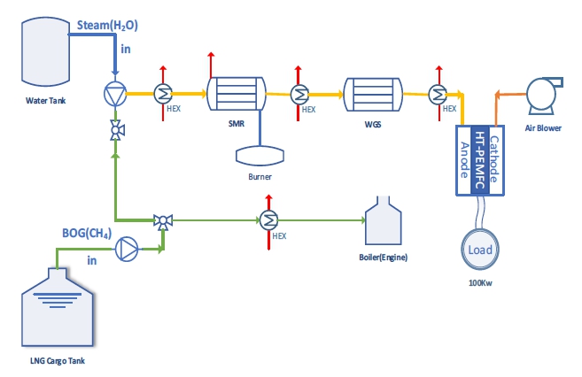
The mechanism for obtaining additional power using the hydrogen generated in the MSR and WGS reactions is shown in Figure 2.
Figure 2 shows the process of producing hydrogen using methane and steam, and obtaining auxiliary power for a ship using a fuel cell. Some of the boil-off gas generated from the LNG cargo tank is used as fuel for ship propulsion and mixed with steam to induce a reforming reaction in the SMR reformer. The reformed gas that has passed through the SMR passes through the WGS again to produce additional hydrogen through the WGS reaction. The reformed gas then flows into the fuel cell to generate auxiliary power for the ship.
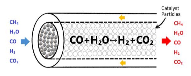
Figure 3 shows the chemical mechanism of the chemical reaction between the catalyst and reactor in the WGS.
Because the WGS is an exothermic reaction, the lower the temperature, the more active the reaction. The reaction results vary, depending on the type of catalyst used.
4. Results and discussion
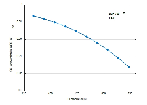
The analysis was based on the case where the pressure of the SMR was 1 bar, and the temperature was 700 °C. The reformed gas from the SMR outlet was introduced into the WGS, and the CO conversion rates in the WGS were compared and analyzed by varying the temperature and pressure.
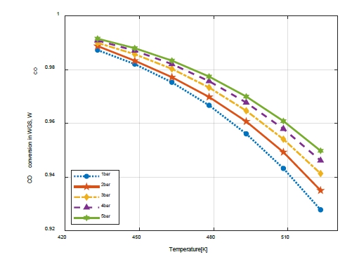
Figure 4 shows the variation in the CO conversion rate with the WGS temperature. The temperature of the WGS varied between 160 and 250 ℃ of the low-temperature WGS reactor. The CO conversion rate in the WGS decreased as the temperature increased.
Figure 5 shows the CO conversion rate as a function of the temperature and pressure in the WGS.
The higher the pressure, the higher the CO conversion rate; however, the range of pressure change was 0.9873–0.9915, indicating a slight difference in value that does not require the consideration of WCO with pressure variation.
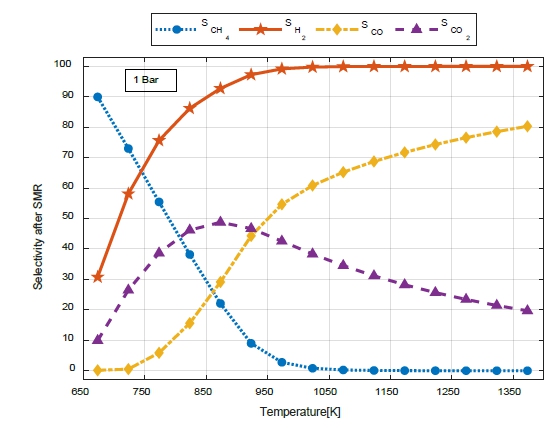
Figure 6 shows the selectivity (S) for CH4, H2, CO, and CO2 with respect to the temperature change at the SMR outlet at 1 bar.
The selectivity (SCH4) decreased owing to an increase in the reaction rate as the temperature increased. Because methane is almost completely converted at 800 K or higher, a value close to zero appeared.
The selectivity (SH2) increased as the temperature of the SMR increased. SCO2 increased up to 600 K and then gradually decreased.
At the SMR outlet, the selectivity (SCO) increased as the temperature increased, compared to that at the WGS outlet. As selectivity (SCO2) increased, selectivity (SCO) increased steeply; however, as selectivity (SCO2) began to decrease, the increase tended to decrease gradually.
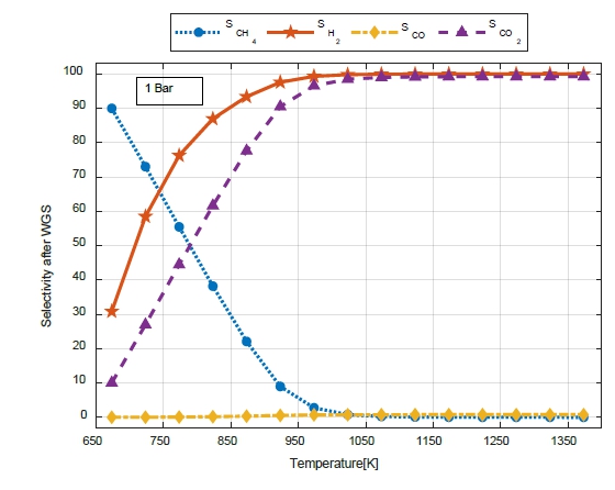
Figure 7 shows the variations in selectivity (S) for CH4, H2, CO, and CO2 with temperature during the SMR when the pressure at the WGS outlet was 1 bar. Because SCH4 does not react at the WGS, it appears to have the same selectivity tendency at the SMR outlet.
In the WGS, SCO was significantly different from that during the SMR. Because CO is smoothly transformed into CO2 through a WGS reaction, the amount of CO decreased over the entire temperature range, and SCO2 increased as the SMR temperature increased.
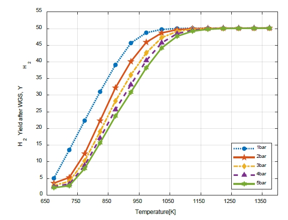
Figure 8 shows the H2 yield (YH2) at the WGS outlet. YH2 increased as the SMR temperature increased. If the reaction occurs at WGS more than only during SMR, the hydrogen yield (YH2) increases as the SMR temperature increases, and the H2 yield (YH2) increases by up to 22.1% compared to that at the SMR outlet.
As the pressure decreased, YH2 increased; however, above 900 K, there was minimal change in YH2 with pressure.
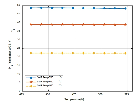
Figure 9 shows the variation in the H2 yield (YH2) with WGS temperature. When the SMR was 700℃, even when the temperature of the WGS was changed, the H2 yield (YH2) did not differ significantly (from 48.75 to 48.34). However, the higher the SMR temperature, the higher the H2 yield (YH2). It is possible to increase the H2 yield (YH2) via a high-temperature reforming reaction. Therefore, CO reduction and H2 can be obtained via the WGS reaction to reduce catalyst poisoning owing to CO generated during the reforming reaction.
5. Conclusion
By installing a WGS reactor, a WGS reaction separate from the reforming reaction can occur. Because of the nature of the WGS reaction, which is a strong exothermic reaction, it is possible to maintain a low temperature, unlike in the high-temperature reformer. In addition, the carbon monoxide conversion rate can be increased to produce additional hydrogen and convert it into carbon dioxide. By varying the variables, such as the temperature and pressure, the following conclusions can be drawn.
(1) The selectivity (S) values of CH4, H2, CO, and CO2 varied significantly, depending on the temperature when passing through SMR. In particular, the selectivity for CO2(SCO2) increased from 48.8 to 99.99%, and the selectivity for CO(SCO) sharply decreased from 80.3 to 0.76. The WGS reaction rate for the SMR rapidly decreased as the temperature increased. However, the separate installation of the WGS reactor increased the reaction rate of CO, resulting in increased CO2 and H2 selectivities and H2 yield.
(2) The installation of a WGS reactor is effective for converting CO into CO2, rather than obtaining hydrogen.
(3) The CO conversion rate can be increased by adding a WGS reactor that performs an exothermic reaction, and the converted CO2 can reduce environmental pollution by installing a CCS.
(4) When the SMR was introduced into the WGS reactor after reacting at 800–900 K, the CO conversion rate in the WGS reactor was the highest, and the CO conversion rate increased as the temperature of the WGS reactor decreased.
(5) During the WGS reaction, as the pressure changed from 1 to 5 bar, the CO conversion rate increased as the pressure increased from 0.9873 to 0.9915. However, an additional power unit was unnecessary for achieving a separate pressure increase.
Nomenclature
| E : | activation energy (kJ/mol) |
| k : | rate constant (1/s) |
| k0 : | pre-exponential factor |
| Keq : | equilibrium constant |
| : | mass flow rate (kg/h) |
| : | molar flow rate (kmol/h) |
| P : | partial pressure (bar) |
| R : | gas constant = 8.314 J/Kmol |
| r : | reaction rate |
| S : | selectivity |
| T : | temperature (K) |
| W : | conversion rate |
| Y : | hydrogen yield |
Subscripts
| m : | concentration exponent of H2O |
| n : | concentration exponent of CO |
Acknowledgments
Author Contributions
Conceptualization, D. H. Hwang and T. W. Lim; Methodology, D. H. Hwang and T. W. Lim; Software, D. H. Hwang; Validation, T. W. Lim and Y. S. Choi; Formal Analysis, D. H. Hwang and Y. S. Choi; Data Curation, D. H. Hwang; Writing—Original Draft Preparation, D. H. Hwang; Writing—Review & Editing, T. W. Lim; Supervision, T. W. Lim.
References
-
S. M. Seyed Mahmoudi, N. Sarabchi, M. Yari, and M. A. Rosen, “Exergy and exergoeconomic analyses of a combined power producing system including a proton exchange membrane fuel cell and an Organic Rankine Cycle,” Sustainability, vol. 11, no. 12, p. 3264, 2019.
[https://doi.org/10.3390/su11123264]

-
S. Marandi, N. Sarabchi, and M. Yari, “Exergy and exergoeconomic comparison between multiple novel combined systems based on proton exchange membrane fuel cells intergrated with Organic Rankine Cycles, and hydrogen boil-off gas subsystem,” Energy Conversion and Management, vol. 244, 2021.
[https://doi.org/10.1016/j.enconman.2021.114532]

-
H. B. Im, S. J. Kwon, C. K. Byun, H. S. Ahn, K. Y. Koo, W. L. Yoon, and K. B. Yi, “Effect of support geometry on catalytic activity of Pt/CeO2 nanorods in water gas shift reaction,” Transactions of the Korean Hydrogen and New Energy Society, vol. 25, no. 6, pp. 577-585, 2014 (in Korean).
[https://doi.org/10.7316/KHNES.2014.25.6.577]

-
F. X. Chiron, G. S. Patience, and S. Rifflart, “Hydrogen production through chemical looping using NiO/NiAl2O4 as oxygen carrier,” Chemical Engineering Science, vol. 66, no. 24, pp. 6324-6330, 2011.
[https://doi.org/10.1016/j.ces.2011.03.060]

-
S. Z. Abbas, V. Dupont, and T. Mahmud, “Kinetics study and modelling of steam methane reforming process over a NiO/Al2O3 catalyst in an adiabatic packed bed reactor,” International Journal Of Hydrogen Energy, vol. 42, no. 5, pp. 2889-2903, 2017.
[https://doi.org/10.1016/j.ijhydene.2016.11.093]

-
R. L. Keiski, T. Salmi, P. Niemisto, J. Ainassaari and V. J. Pohjola, “Stationary and transient kinetics of the high temperature water-gas shift reaction,” Applied Catalysis A, General 137, pp.349-370,1996.
[https://doi.org/10.1016/0926-860X(95)00315-0]

-
Y. Wang, Y. H. Chin, R. T. Rozmiarek, B. R. Johnson, Y. Gao, J. Watson, A. Y. L. Tonkovich, and D. P. Vander Wiel, “Highly active and stable Rh/MgOAl2O3 catalysts for methane steam reforming,” Catalysis Today, vol. 98, no. 4, pp. 575-581, 2004.
[https://doi.org/10.1016/j.cattod.2004.09.011]

- U. Cheon, K. S. Ahn, and H. K. Shin, “Study on the characteristics of methanol steam reformer using latent heat of steam,” Transactions of Korean Hydrogen and New Energy Society, vol. 29, no. 1, pp. 19-24, 2018.
-
Y. H. Lee, “Analysis of the characteristics of reformer for the application of hydrogen fuel cell systems to LNG fueled ships”,Journal of the Korean Society of Marine Environment & Safety, Vol. 27, No. 1, pp. 135-144,2021(in Korean).
[https://doi.org/10.7837/kosomes.2021.27.1.135]

-
J. Xu and G. F. Froment, “Methane steam reforming, methanation and water-gas shift: I. Intrinsic kinetics,” AIChE Journal, vol. 35, no. 1, pp. 88-96, 1989.
[https://doi.org/10.1002/aic.690350109]

- H. J. Lee, and et al. “Kinetic model of steam-methane reforming reactions over Ni-Based catalyst,” Korean Chemical Engineering Research, vol. 56, no. 6, pp. 914-920, 2018 (in Korean).
-
W. H. Cassinelli, L. S. F. Feio, J. C. S. Araújo, C. E. Hori, F. B. Noronha, C. M. P. Marques, and J. M. C. Bueno “Effect of CeO2 and La2O3 on the activity of CeO2 La2O3/Al2O3-supported Pd catalysts for steam reforming of methane,” Catalysis Letters, vol. 120, pp. 86-94, 2008.
[https://doi.org/10.1007/s10562-007-9253-z]

-
J. R. Rostrup-Nielsen, J. Sehested, and J. K. Norskov, “Hydrogen and synthesis gas by steam- and CO2 reforming,” Advanced in Catalysis, vol. 47, pp. 65-139, 2002.
[https://doi.org/10.1016/S0360-0564(02)47006-X]

-
T. -W. Lim, “Performance analysis and design of steam methane reforming reactor for hydrogen production,” Journal of Fisheries and Marine Sciences Education, vol. 34, no. 5, pp. 902-910, 2022 (in Korean).
[https://doi.org/10.13000/JFMSE.2022.10.34.5.902]

-
R. L. Keiski, O. Desponds, Y. F. Chang, and G. A. Somorjai, “Kinetics of the water-gas shift reaction over several alkane activation and water-gas shift catalysts,” Applied Catalysis A: General, vol. 101, no. 2, pp. 317-338, 1993.
[https://doi.org/10.1016/0926-860X(93)80277-W]


