A Study on Effects of Partial Shading on PV System applied to the Offshore Plant
Copyright © The Korean Society of Marine Engineering
This is an Open Access article distributed under the terms of the Creative Commons Attribution Non-Commercial License (http://creativecommons.org/licenses/by-nc/3.0), which permits unrestricted non-commercial use, distribution, and reproduction in any medium, provided the original work is properly cited.
Abstract
Unlike photovoltaic systems installed on land, photovoltaic systems applied to the offshore plant have the characteristic that is installed in a limited space. For single point mooring plant, it is advantageous in terms of a reliable power supply to be installed in different directions of photovoltaic panels, because it is not possible to identify the position of the sun by rotation of the plant itself. Differences of installation angle between photovoltaic panels make a difference of the intensity of radiation irradiated on each photovoltaic panel, and it brings loss of generation quantity due to the partial shading. In order to provide a photovoltaic system suitable for offshore plant, the modeling which contains multiple photovoltaic panels controlled by single controller is performed. Then, it was examined how the output characteristics of the photovoltaic system change about the difference of the intensity of radiation that varies depending on the altitude of the sun. Finally, through the simulation, a development model of the photovoltaic system which is suitable for offshore plant is suggested.
Keywords:
Solar photovoltaic system, Photovoltaic modeling, Partial shading, Maximum power point, Offshore plant1. Introduction
Interest in Offshore plant market is rapidly increasing because resources mined on the land become depleted. Installation sea area of offshore plant is moving more and more to deep sea, requirement performance associated with this is increased, and the required power is also increasing.
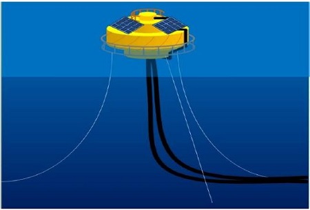
As the marine environment regulations is recently strengthen, renewable energy such as solar cells is being used to generate power. In particular, SPM (Single point mooring) system is supplied power primarily through the battery, and some products is also possible to generate the power with solar cells. Figure 1 shows the PV system applied to SPM.
But, the solar power system applied offshore plant, unlike the solar power system installed on land, there are constraints that must be installed in a limited area. The case of SPM system, the directions for receiving sunlight are possible to be varied by being rotated.
In terms of installation and stable power supply, panels of solar power system applied to offshore plant is set in several directions. However, when placed in the several directions of solar panels, the difference of the amount of light between panels makes partial shading problems. This would reduce the output of the solar system.
In this paper, the output characteristic is simulated when the solar power system sets in several directions applied to a SPM systems. And the configuration of solar power system suitable for offshore plants has been proposed.
2. Solar Power Generation Modeling
2.1 Solar Cell Model
Many equivalent circuits have been proposed in the literature in order to assess the behaviour of the PV cell. The most commonly used equivalent circuits are the single diode models. These models are assumed that there is no recombination loss in the depletion region. But, real solar cell, the recombination loss represents a substantial loss, especially at low voltages. In the high voltage, diode ideality factor is 1 and in the low voltage, diode ideality factor is 2. So, consideration of this loss can draw a more precise model known as the two-diode model.
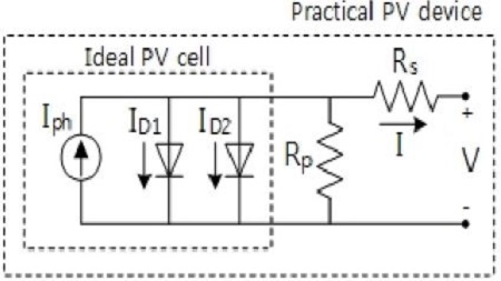
Figure 2 shows the equivalent circuit for solar cell based on two diode model. Using Kirchhoff’s first law, the output current of the cell is given by Equation (1).
| (1) |
Iph is proportional to the sun irradiance and the cell temperature, and it can be given by Equation (2)
| (2) |
Isc is the light-generated current at 25℃ and 1000W/m2 irradiation. Tref is Nominal temperature at 25℃. Gn , the nominal irradiation, is 1000W/m2. Isc , KI and Tref can be obtained from the PV cell data sheet.
ID1 is the current dut to the diode action (corresponds to the diode D1), and ID2 is the recombination process in the depletion region (corresponds to the diode D2). These are following Equation (3), (4) and (5).
| (3) |
| (4) |
| (5) |
To simplify this, some researchers assumed that α1 =1 and α2 =2. These values are approximation of the Schokley – Read - Hall recombination in the space charge layer of the photodiode.
Equation (6) can be expressed by diode saturation current of the temperature variations.
| (6) |
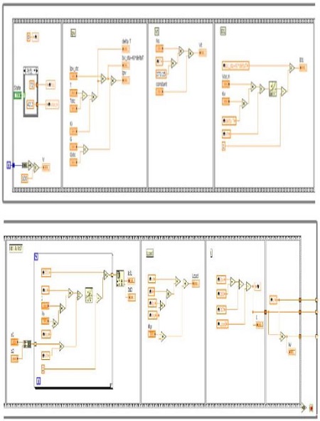
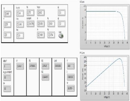
Figure 3 and Figure 4 show a block diagram and front panel of solar cell by LabVIEW respectively.
2.2 Solar Array Model
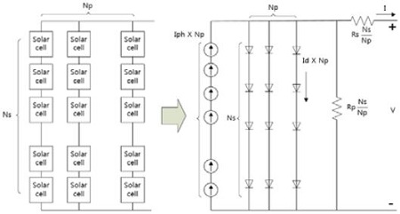
In the typical PV generation system, the modules are configured in a series-parallel structure as shown Figure 5.
In this case, the output current can be given by Equation (7).
| (7) |
Ns and Np are the number of series and parallel connected in solar cells in a array, respectively.
2.3 Partial Shaded Module in Series
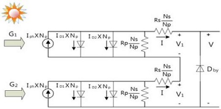
In the marine environment, solar generation system is installed in different directions. Differences of installation angle between PV panels make a difference of the intensity of radiation irradiated on each PV panel, and it brings loss of generation quantity due to the partial shading effect. Figure 6 shows the series configuration of two PV modules that receive irradiance of G1 and G2 respectively.
The output current and voltage in partial shaded module can be obtained by solving the following formula Equation (8), Equation (9)
| (8) |
| (9) |
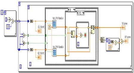
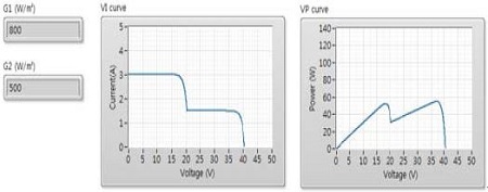
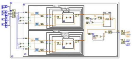
Figure 7 and 8 show a block diagram and front panel of solar array by LabVIEW respectively.
2.4 Irradiation Modeling
In order to simulate the reliable power characteristics of the solar power system, solar irradiation data measured for a long time is required. However, in order to measure these data, there is a difficulty in equipment management, compensation, cost, etc. If the measurement is difficult, the calculating models of the amount of solar irradiation is made. These models have been used for studies such as the tilt angle and azimuth angle of the solar panels. In this chapter, a daily model of the solar irradiation which can be applied to the model of the solar power system is provided.
Hour angle is a value converted by moves of sun each times, and it moves 15° every time. it has negative values in the morning, positive values in the afternoon, and becomes 0° at noon. Hour angle can be derived by the following equation.
| (10) |
Local solar time is shown by correcting local time, by applying the number of days, earth's axis and longitude of the measurement position.
Decline angle is occurred by tilting of earth's axis, 23.5°. It can be calculated by the following formula Equation (11).
| (11) |
Decline angle will change depending on the season, and is the maximum at 23.45° at summer solstice, is the lowest at -23.45° in the winter solstice, and becomes 0° at the autumnal equinox and the vernal equinox.
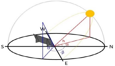
Elevation angle refers to the height of the sun measured from the horizontal line. There is a zenith angle in a similar concept, and is calculated by (90°-elevation angle).
| (12) |
Azimuth angle is the angle between the due north direction and directions that sunlight comes from. Azimuth angle varies with the date of the year and latitude of measurement position in general.
| (13) |
When the elevation angle and azimuth angle of solar is determined, and the tilted angle and azimuth angle of solar panel is given, the amount of light irradiated on the solar panel can be represented by the following formula.
| (14) |
3. Simulation
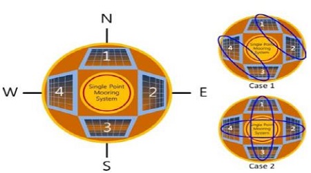
The solar power system applied offshore plant, unlike the solar power system installed on land, there are constraints that it must be installed in a limited area. The case of SPM system, the directions of solar panel for receiving sunlight are installed in 4 directions by being rotated. It is shown at Figure 10.
To analyze the partial shading effect on the output of the proposed configuration, two case studies are considered as Case 1, Case 2.
Case1 is consist of No. 1 and No. 2 connected by series and No. 3, No. 4 connected by series, respectively. And they are connected in parallel. Case2 is consist of No. 1, No. 3 connected by series and No. 2, No. 4 connected by series, respectively. And they are connected in parallel. Figure 11 is the block diagram of each cases.
3.1 Environmental condition
At first, we selected PV panel and examine specification. Table 1 shows the specifications for the BP MSX 60.
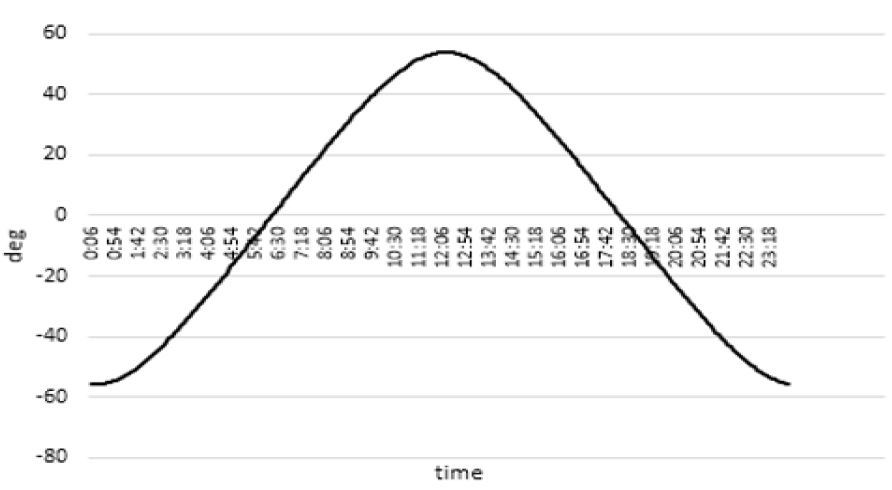
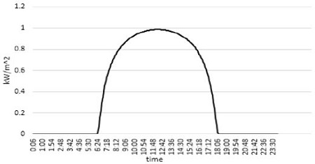
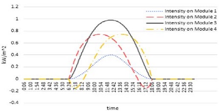
Figure 12, 13 and 14 show the elevation angle, solar irradiation and intensity on modules, respectively. Negative value means that the sun is located below the horizon. It was simulated in the autumn equinox (September 23).
3.2 Result Analysis
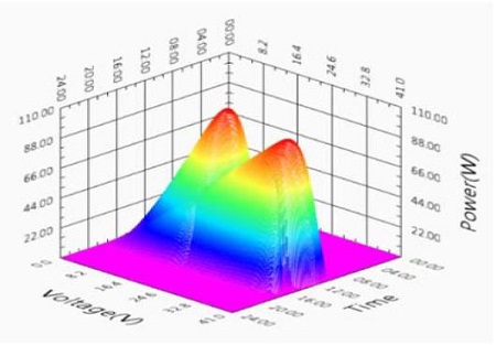
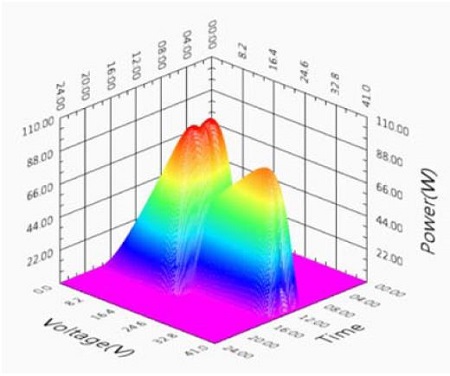
The output characteristic will be results in three dimensional characteristic shown in Figure 13 and 14. In this figure, x axis is the time (September 23), y axis is the output voltage of the solar array, and z axis is the output power of the solar array, respectively.
In the results of case 1, the maximum power points are located in region 1 and 2. But, in the result of case 2, the maximum power points are located in region 1.
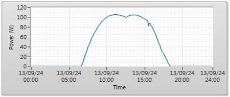
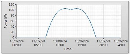
In the Figure 15 and 16, the graph of the maximum generated power are approximately similar to case 1 and case 2.
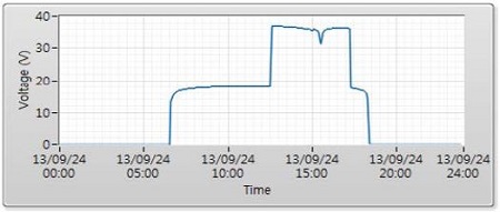
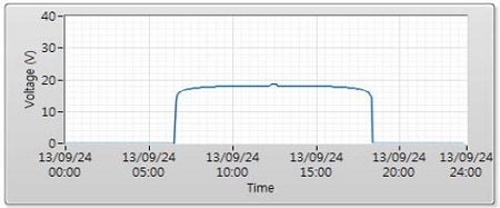
Figure 17 and 19 are maximum power and voltage at maximum power point in Case 1. Figure 18 and Figure 20 are maximum power and voltage at maximum power point in Case 2. It means that Case 2 (the opposite-side panel connected by series) is better than Case 1 (the close-side panel connected by series) from a control perspective.
4. Conclusions
In this paper, PV system simulator by LabVIEW based on two-diode model is proposed. To comparison of the effect of partial shading by PV system configuration in the marine environment (installed in 4 directions by being rotated), it was simulated using a range of irradiance levels for one day.
As a conclusion, the opposite-side panel connected by series is better than the close-side panel connected by series on the same irradiation.
Nomenclature
| Iph : | Short circuit current due to sunlight [A] |
| ID1 : | Current shunted through the No.1 diode [A] |
| ID2 : | Current shunted through the No.2 diode [A] |
| Rp : | Parallel resistance of cell [Ω] |
| Rs : | Series resistance of cell [Ω] |
| ISC : | The light generated current at the nominal condition [A] |
| KI : | Short circuit current/temperature coefficient [I/K] |
| Tc : | Current shunted through the No.2 diode [A] |
| Tref : | Nominal temperatures [K] |
| G : | The irradiation on the device surface [W/m2] |
| Gn : | The nominal irradiation [W/m2] |
| I01 : | Diode 1 saturation current [A] |
| I02 : | Diode 2 saturation current [A] |
| V : | Cell output voltage [V] |
| α1 : | Diode 1 ideal constant |
| α2 : | Diode 2 ideal constant |
| VT : | Thermal voltages [V] |
| K : | Boltzmann constant (1.38×10⁻²³J/K) [J/K] |
| q : | Electron charge (1.602×10⁻¹⁹C) [C] |
| Isc,n : | Short circuit current [A] |
| Voc,n : | Open circuit voltage [V] |
| KV : | Short circuit voltage/temperature coefficient [V/K] |
| Ns : | Number of series connected in PV |
| Np : | Number of parallel connected in PV |
| HA : | Hour angle [deg] |
| TLS : | Local solar time [min] |
| d : | Day of year (1~365) |
| h : | Elevation angle of solar |
| δ : | Decline angle [deg] |
| La : | Latitude |
| SPV : | Amount of light incident on the solar panel |
| Sdirect : | Amount of light in a plane perpendicular to the light of the sun |
| θ : | Tilted angle of solar panel |
| α : | Azimuth angle of solar |
| β : | Azimuth angle of solar parnel |
| Pmax : | Maximum Power [W] |
| Vmp : | Voltage at Pmax [V] |
| Imp : | Current at Pmax [A] |
Acknowledgments
This paper is extended and updated from the short version that appeared in the Proceedings of the International Symposium on Marine Engineering and Technology (ISMT 2014), held at BEXCO, Busan, Korea on October 17-19, 2014.
References
-
K. Ishaque, Z. Salam, and H. Taheri, “Accurate MATLAB simulink PV system simulator based on a two-diode model,”, Journal of Power Electronics, 11(2), p179-187, (2011).
[https://doi.org/10.6113/JPE.2011.11.2.179]

-
A. Islam, and I. B. Chowdhury, “A Simulink based generalized model of PV cell/array,”, Developments in Renewable Energy Technology (ICDRET), (3), p1-5, (2014).
[https://doi.org/10.1109/ICDRET.2014.6861683]

- N. Belhaouas, M. S. A. Cheikh, A. Malek, and C. Larbes, “Matlab-simulink of photovoltaic system based on a two-diode model simulator with shaded solar cells,”, Journal of Revue des Energies Renouvelables, 16(1), p65-73, (2013).
- R. Ramaprabha, and B. L. Mathur Dr. , “Impact of partial shading on solar PV module containing series connected cells,”, International Journal of Recent Trends in Engineering, 2(7), p56-60, (2009).
-
H. Patel, and V. Agarwal, “Maximum power point tracking scheme for PV systems operating under partially shaded conditions,”, IEEE Transactions on Industrial Electronics, 55(4), p1689-1689, (2008).
[https://doi.org/10.1109/TIE.2008.917118]

-
M. Seyedmahmoudian, S. Mekhilef, R. Rahmani, R. Yusof, and E. T. Renani, “Analytical modeling of partially shaded photovoltaic systems,”, Energies, 6(1), p128-144, (2013).
[https://doi.org/10.3390/en6010128]

-
Y. Jiang, J. A. A. Qahouq, and M. Orabi, “Matlab/Pspice hybrid simulation modeling of solar PV cell/module,”, Proceedings of the Applied Power Electronics Conference and Exposition (APEC), p1244-1250, (2011).
[https://doi.org/10.1109/APEC.2011.5744752]

-
K. S. Tey, and S. Mekhilef, “Modified incremental conductance algorithm for photovoltaic system under partial shading conditions and load variation,”, IEEE Transactions on Industrial Electronics, 61(10), p5384-5392, (2014).
[https://doi.org/10.1109/TIE.2014.2304921]

- K. S. M. Raza, H. Goto, and H. Guo, “An improved and very efficient MPPT controller for PV systems subjected to rapidly varying atmospheric conditions and partial shading,”, Power Engineering Conference, (1), p1-6, (2009).
- M. Sarvi, M. H. Tabatabaee, and I. Soltani, “A fast maximum power point tracking for mismatching compensation for PV systems under normal and partially shaded conditions,”, Journal of Mathematics and Computer Science, 8(8), p52-74, (2014).
-
H. Altas, and A. M. Sharaf, “A photovoltaic array simulation model for Matlab-Simulink GUI environment,”, Proceedings of the International Conference on Clean Electrical Power, 7(1), p341-345, (2007).
[https://doi.org/10.1109/ICCEP.2007.384234]

-
M. G. Villalva, J. R. Gazoli, and E. R. Filho, “Comprehensive approach to modeling and simulation of photovoltaic arrays,”, IEEE Transactions on Industrial Electronics, 24(5), p1198-1208, (2009).
[https://doi.org/10.1109/TPEL.2009.2013862]


