A Study on Power Performance of a 1kW Class Vane Tidal Turbine
Copyright © The Korean Society of Marine Engineering
This is an Open Access article distributed under the terms of the Creative Commons Attribution Non-Commercial License (http://creativecommons.org/licenses/by-nc/3.0), which permits unrestricted non-commercial use, distribution, and reproduction in any medium, provided the original work is properly cited.
Abstract
Recently, tidal current energy conversion is a promising way to harness the power of tides in order to meet the growing demands of energy utilization. A new concept of tidal current energy conversion device, named Vane Tidal Turbine (VTT), is introduced in this study. VTT has several special features that are potentially more advantageous than the conventional tidal turbines, such as propeller type tidal turbines. The purpose of this study on VTT is to analyze the possibility of extracting the hydrokinetic energy of tidal current and converting it into electricity, and evaluate the performance of turbines for various numbers of blades (six, eight and twelve) using Computational Fluid Dynamics (CFD). At various tip-speed ratios (TSR), the six-bladed turbine obtains the highest power and torque coefficients, power efficiency is up to 28% at TSR = 1.89. Otherwise, the twelve blade design captures the smallest portion of available tidal current energy at all TSRs. However, by adding more blades, torque extracted from the rotor shaft of twelve-bladed turbine is more uniform due to the less interrupted generation of force for a period of time (one revolution).
Keywords:
Vane tidal turbine, Computational fluid dynamics, Power coefficient, Tidal current energy, Torque coefficient1. Introduction
In order to meet the human's aspiration for energy security, reducing dependence on finite and polluting fossil fuels and to struggle against the climate change, the available natural and sustainable resources all over the world were exploited. The oceans, which cover more than two-thirds of our planet, offer an incredible store of energy. One of the forms of energy within the oceans is that resulting from the gravitational effects of the planetary motions of the Earth, the Moon and the Sun, which produce the tides that drive strong marine currents. Tides possess both potential and kinetic energy. Tidal energy can be utilized by capturing potential energy i.e., by means of tidal barrage and tidal fence, or by capturing kinetic energy i.e., by means of tidal current turbines. This study is focused on a vane type tidal current turbine that captures kinetic energy. The research on tidal energy is underway around the globe [1]-[3], and the technology has been tested in many countries [4]-[6]. At present, there are many kinds of tidal current energy conversion devices which have been powerfully developing by researchers from many countries all over the world, such as propeller type turbines, Darrieus types turbines, and so on.
Recently, there is a study on water wheel turbines using computational fluid dynamics simulation [7], which was done for two kinds of blade design in shape (triangle and rectangle), the influence of number of blade (four and six) is also taken into account. This research on water wheel turbines indicated that the triangular blade design show weak performance compared to rectangular one (about 30% reduction in efficiency). Derived from the similar concept, we have been developing a new type of horizontal axis turbines that is optimized for tidal applications. This turbine is named Vane Tidal Turbine (VTT) and is planned to be installed in areas with high potential of tidal energy, such as banks, estuaries and so on.
Originally, VTT was designed with twelve blades and was carefully analyzed in previous studies [8][9]. It is found that generated power was unexpectedly low at 1m/s cut-in velocity of water flow and 10 rpm rotational speed of the rotor. Thus, in this study, the scope is broadened to discover VTT’s capability for different numbers of blades (six, eight and twelve). As a result, by analyzing the power coefficient and torque coefficient values, a solution for VTT design can be found.
2. Vane Tidal Turbine
2.1 Turbine Classifications
According to classifications of the turbines [10][11], there are two main configurations: horizontal (axial-flow) and vertical axis turbines. The alignment of rotor axis with respect to water flow can be categorized into two: one category classifies turbines into two types including horizontal axis and cross flow turbine whose cross flow is divided into two types of in-plane and vertical axis, and another category classifies turbines into three types: horizontal axis, vertical axis and cross flow turbine.
Axial-flow (alternatively called horizontal axis) turbines have axis parallel to the fluid flow and employ propeller type rotors. The cross-flow turbines have rotor axis which is orthogonal to the water flow but parallel to the water surface. They can be divided into vertical axis (axis vertical to water plane) and inplane axis (axis on the horizontal plane of the water surface). The in-plane turbines are generally drag based devices (the blade speed is less than water speed) and said to be less efficient than their lift-based counterparts (the blade is faster than the water) [12]. Conventionally, the forces on an approximately two-dimensional body such as a turbine blade are decomposed into the component parallel to the fluid flow, known as “drag”, and the component perpendicular to the relative fluid flow, known as “lift”. Rotor designs employ either the drag force (with negligible lift) or the lift force (with minimal drag) to generate all or most of the torque [13].
2.2 Turbine Design Parameters
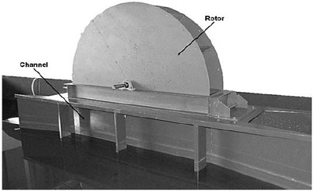
From the features mentioned in the turbine classifications above, the VTT can be classified in the group of in-plane turbines. Figure 1 shows the experimental model in test bed. VTT has just one moving part (it can be called by “wheel” or “rotor”) which rotates around a horizontal axis. The wheel has two major components:
- The central hub: This is a horizontal cylinder which is connected to the driven shaft of the current conversion equipment.
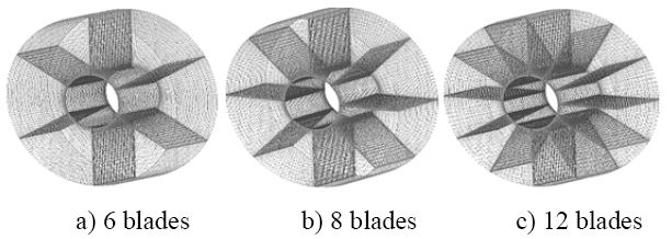
- Rotor blades: The blades are the surfaces on which the water's energy is extracted. These thin rectangular blades are arranged in radial position from the hub. There are three types of blade numbers (six, eight and twelve) which are designed for simulation testing.
Additionally, stationary part is equipped with auxiliary and supporting machineries, including:
- Conversional equipment: This is connected to the shaft located in the central hub through a belt transmission and a gear box. It is used to convert the hydrokinetic energy of the tidal streams into electricity.
- Channel: It provides a mounting for the wheel bearings and other parts. The inlet of the channel is narrowed to concentrate the water flow and accelerate the inflow velocity based on De Laval’s law. The outlet of the channel also has the same geometry as the inlet.
The design parameters for modeling in computational simulation are summarized as shown in Table 1.
3. Theory and Numerical Method
3.1 Theory
At a depth of water, d with density, ρ of water, under the influence of gravity, g, the pressure P can be defined as follows [14]:
| (1) |
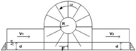
Referring to Figure 2, consider a simple vertical plate which is submerged in water with the depth, d. The triangles represent the hydrostatic pressure. The force acting on either sides of this plate (its width, w), F[14], is defined as follows:
| (2) |
If it is now imagined that the plate moves laterally with velocity, V, the power at the plate available from water flow, Pa, is:
| (3) |
Where A is the cross section area of the plates submerged in water under consideration (m2):
| (4) |
The water wheel converts a part of this power to the shaft’s power, Pshaft[9]:
| (5) |
Where CP is the power coefficient of the wheel and represents the ratio between the power output from the wheel and power available in the water. Not all of the available power is converted into the shaft power by the wheel. Leaving water should have sufficient kinetic energy to continue its way outside the wheel. The above equations show that the power output from the wheel depends on the power available in the water and the efficiency of the wheel.
In order to conveniently analyze and evaluate performance of the turbine at different rotational speeds, the runner’s velocity is normalized by the incoming water velocity and a nondimensional parameter, called “tip-speed ratio” (λ), is used and defined as follows [15]:
| (6) |
Where R is rotor’s radius (mm), ω is rotational speed (rad/s), Vin is inflow velocity (m/s). Tip speed ratio is related to the efficiency, and in this paper, the study is carried out with a range of TSR by fixing the rated cut-in velocity at 2 m/s and varying the rotational speed, as shown in Table 2.
In addition to power coefficient CP, this study also uses torque coefficient CQ to evaluate the torque extraction from the wheel’s shaft. This non-dimensional parameter, which is depended on the value of TSR, is calculated and expressed in Equation (7) below:
| (7) |
Where T is torque extracted from the shaft of rotor (Nm). It is produced by the rotation of the wheel due to the water flow acting on the blade’s surface.
3.2 Modeling and meshing
A three-dimensional model of this turbine and its flow field are designed and numerically discretized in computational simulation. Power performance and characteristics of VTT are analyzed using CFD commercial code, ANSYS 14. Meshing is done using ICEM CFD. Hexahedral grid is applied and results in mesh size of 313,000 nodes for the stationary part (inlet, outlet, bedplate, side walls).
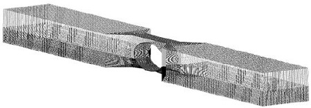
All three types of this turbine’s runner are resulted in relatively similar mesh size, about 530,000 nodes despite of difference in number of blades. This is enough for the given computational problem and assures accurate results according to the previous numerical study [16]. Figure 3 illustrates mesh formation for the three configurations of the rotor. Figure 4 shows mesh illustration for stationary frame of the calculation domain, including inlet, outlet, bed plane, side walls, and opening parts.
3.3 Calculation domain and boundary conditions
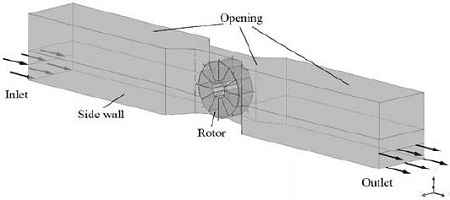
The computational domain is shown in Figure 5. Two ends of the channel (inlet and outlet) are lengthened ten times as many as the runner’s width. This is sufficient for computational simulation and capable of capturing the wake characteristics. Inlet boundary is set to “Cartesian velocity components”, outlet boundary is average static pressure, and opening boundary condition is “Opening pressure and direction”. The blades, hub, channel, bedplate and side walls are all no-slip wall boundaries. The mesh connection between the rotating and stationary frame is general connection interface boundary, and is set to “Transient rotor stator”. The working fluids are defined as sea water and air at 25oC. Turbulence model is shear stress transport (SST), with turbulence intensity set to 5% for the whole flow-field. Simulation is done in transient by ANSYS CFX Solver.
Time dependent behavior for transient simulation in CFD is specified through time duration and time step. The time-step option provides a way to track the progress of real time during the simulation, whereas time duration is a user-specified limit on the length of real time the simulation is to run. In order to save computational resources and be convenient to compare the turbine efficiency among three kinds of VTT, but still ensure to achieve the accurate simulation results, this study uses sufficiently long revolutions of the rotor, since the torque generation will be stable from the initial revolution onwards. Time dependence is set based on the values of rotational speed to effectively get convergence.
4. Results and Discussions
4.1 Averaged pressure contours and velocity vectors
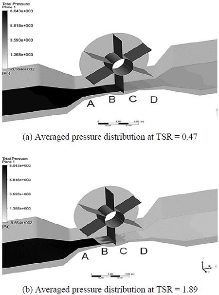
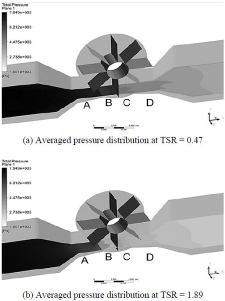
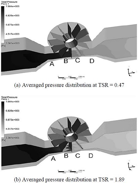
Analysis of simulation results was post-processed using a relatively advanced hardware system, which is comprised of 8 Intel CPUs (Quad-core of 3.1 GHz). Visualizations of averaged pressure distribution for VTT with three kinds of blade numbers at different TSRs are shown from Figure 6 to Figure 8. These figures present the surfaces of averaged pressure contours which are distributed over the length of the channel from inlet to outlet. In all cases, the view of averaged pressure distribution is oriented from the left (high pressure side, expressed by darker color) to the right (low pressure side, expressed by lighter color), the area with grey scale illustrates the variance of fluid pressure between the highest pressure and the lowest pressure. The averaged pressure contours plane is marked as four regions: A, B, C, D. Region A illustrates the pressure value distributed from the inlet of the channel to the entrance of rotor, where water is about to contact to the blades. Regions B and C show the pressure distribution of water stream in the spaces between two adjacent blades. And the last one, region D, is a position where water flows out of the rotor and keep flowing to the outlet of the channel.
Figure 6 shows averaged pressure distribution for six-bladed type at highest and lowest TSRs. At TSR = 0.47 (lowest rotational speed, 10 rpm), it is obvious that the difference in pressure color for water flow among four regions is relatively small, especially regions A and B. It means that the hydrokinetic energy of water flow after passing through the rotor is still large. However, in cases of the higher values of TSR (higher rotational speed), the difference in pressure between regions A and D is more distinguished and the water current energy is extracted more effectively than that at TSR = 0.47.
Figure 7 and 8 show the averaged pressure contours of eight-bladed and twelve-bladed turbines, respectively. In both cases, the averaged pressure distributions at regions A, B, C and D are similar to the case of six-bladed turbine. In the other words, at higher TSRs (higher rotational speeds), the pressure color in regions B, C and D is much different in comparison with region A at TSR = 0.47. It proves that at higher rotational speed of the rotor, the possibility of power extraction for all types of VTT is better and more effective.
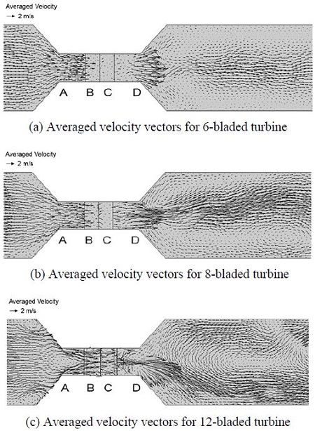
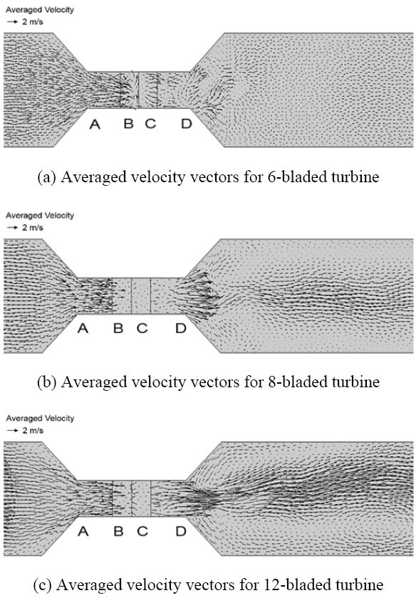
Figure 9 and 10 illustrate averaged velocity vectors for three types of VTT at different TSRs. In general, the averaged velocity vectors at each TSR express the change of hydrokinetic energy inside water flow that is analyzed and evaluated similarly to the change of pressure when the water flows through the wheel. At TSR = 0.47, compared to region A, the magnitude of averaged velocity vectors of twelve-bladed turbine at downstream locations (the regions B, C and D) is still large and there is no considerable change. In comparison with six-bladed and eight-bladed turbines, the averaged velocity vectors of water flow for twelve-bladed type at region B, C and D have higher magnitudes than those of two other types of VTT. Additionally, the direction of the averaged velocity vectors of the water flow in region B, C and D of twelve-bladed turbine is more turbulent and the quantity of vectors is denser than that of six-bladed and eight-bladed types. In most cases of TSR, the magnitude of averaged velocity vectors for six-bladed type gets the lowest rate at the region B, C and D; it means that this design of VTT has the highest energy absorption rate among given configurations. Conversely, the twelve-bladed type utilized the flow’s energy at least. Consequently, the extracted power and the power coefficient of six-bladed turbine have the highest value, and the twelve-bladed type produces the lowest power output as well as power coefficient.
In short, from the visualizations of pressure contours at various TSRs, at 2 m/s inflow velocity and 40 rpm rotational speed of the wheel (corresponding to TSR = 1.89), all three types of VTT has ability to absorb the highest kinetic energy of the water current comparing to the other values of TSR.
4.2 Turbine efficiency
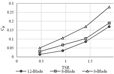
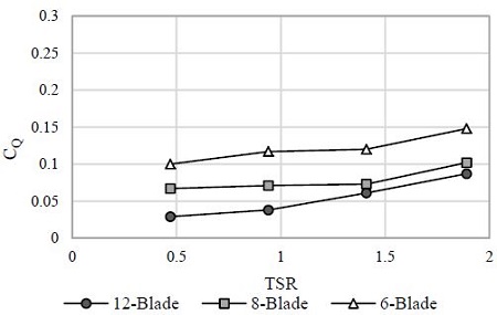
Power performances of VTT are evaluated by power coefficient CP and torque coefficient CQ which are expressed in Figure 13 and 14, respectively. The figures express CP and CQ as a function of TSR and show the performances of three configurations of VTT with different blade numbers (six, eight and twelve blades). The study is carried out with several TSRs by varying the rotational speed from 10 to 40rpm within given revolutions of the rotor.
Both CP and CQ show the same patterns which are inclined to rise up from the lowest to the highest TSRs. According to the results depicted in Figure 13, the power coefficient of sixbladed type achieves the highest value compared to the others in all cases of TSRs. At TSR = 1.89, the six-bladed type reaches up to 28% power coefficient which is about six times as much as the value at TSR = 0.47. For twelve-bladed turbine, it generates the lowest of power coefficient in comparison with those at the other TSRs.
Similar to the power coefficient chart, as shown in Figure 14 of torque coefficient that is a similar non-dimensional analysis for the torque [10], the six-bladed turbine keeps showing its predominant performance comparing to the others with various TSRs, meaning that the torque extracted from the rotor’s shaft of this turbine always gets higher than two other kinds of VTT. On the contrary, it is clearly seen that the tidal current energy conversion capability of the twelve-bladed type is the smallest compared to the others at the same TSR, since the generated torque coefficient of this kind only attains 8.7%, which is a half as low as that of six-bladed type, at the highest rotational speed (TSR = 1.89).
All these results of turbine efficiency are reasonable and can be explained by the characteristics of flow patterns, including averaged pressure contours and velocity vectors distribution as discussed above, where high efficiency is found at the cases with obvious change in averaged pressure distribution of water flow before and after the rotor, and the lower averaged velocity magnitude of fluid when running out of the rotor.
In summary, from the curves of power coefficient CP and torque coefficient CQ, the six-bladed turbine shows the best performance at all TSRs, especially at TSR = 1.89 (corresponding to 2m/s inflow velocity and 40rpm rotational speed of the rotor). Its greatest values at TSR = 1.89 can be explained by the change of averaged pressure distribution as well as the display of averaged velocity vectors from the Figure 6 to Figure 12, when compared to the other TSRs.
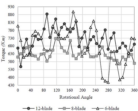
As shown in Figure 15, it illustrates the variation of torque extracted at the rotor’s shaft due to the water flow acting on the blades at TSR = 0.47 for all three kinds of VTT within one revolution of the rotor. The six-bladed results show that when submerged in the water, one blade needs to be inclined with at least 18 degrees angle to start contributing to the torque’s generation. The blade contributes by producing torque until about 54 degrees; after that, the contribution becomes negative. That means the blade will be active for 36 degrees of the 90 degrees inside the water. Meanwhile, with the same 90 degrees of one blade submerged in the water, the twelve-bladed turbine just needs 9 degrees angle starting to produce the positive torque until 27 degrees. However, it is clearly seen that in one revolution of the rotor, the six-bladed turbine only has six times for generating the positive torque. In contrast, the twelve-bladed type has twelve times contributing to the positive torque. Thus, by adding more blades, torque generated from the turbine will be improved by contributing to the positive torque [3]. The torque generation in one revolution of the wheel (corresponding to 360 degrees rotational angle) for twelve-bladed type is more continuous, and the number of blades takes part into generating torque is more than the other types of VTT, although the power coefficient and torque coefficient are lower.
5. Conclusions
We carried out a computational evaluation of a new tidal current conversion device with a variety of blade numbers (six, eight and twelve blades), which has several obvious advantages, such as: simple structure, easy to manufacture, convenient to maintain and repair. To sum up, the following conclusions are given.
1) The six-bladed turbine shows its predominant performance comparing to the other types of VTT in this study. At various TSRs, the six-bladed type obtains the highest power coefficient and torque coefficient, especially reaching up to 28% power coefficient and 14.8% torque coefficient at TSR = 1.89.
2) The twelve-bladed turbine captures the lowest tidal current energy in comparison with the six and eight-bladed designs at all TSRs. However, by adding more blades, the torque extracted from the shaft of twelve-bladed turbine is more continuous.
The capability of VTT with different number of blades in this paper has not been fully comprehended yet, since various factors were excluded, i.e. impacts of flow rates or water level, shape of channel and blades, comparison between the experimental and computational results, etc. These parameters should be investigated and taken into account in future work in order to evaluate the optimal design for VTT. Nevertheless, the results of this study will be contributing to the present development of tidal current energy conversion devices as well as the promising method of tidal energy conversion to serve the future growing demands of renewable energy.
Acknowledgments
This research was a part of the project titled “Interaction Study for Optimal Tidal Farm,” funded by the Ministry of Oceans and Fisheries, Korea.
This paper is extended and updated from the short version that appeared in the Proceedings of the International Symposium on Marine Engineering and Technology (ISMT 2014), held at BEXCO, Busan, Korea on October 17-19, 2014.
References
- T. Setoguchi, K. Kaneko, M. Maeda, T. W. Kim, and> M. Inoue, “Impulse turbine with self-pitch controlled guide vanes for wave power conversion : Performance of monovane type,”, International Journal Offshore Polar Engineering, 3(1), p73-78, (1993).
-
T. Setoguchi, S. Santhakumar, H. Maeda, M. Takao, and K. Kaneko, “A review of impulse turbines for wave energy conversion,”, Journal of Renewable Energy, 23(2), p261-292, (2001).
[https://doi.org/10.1016/S0960-1481(00)00175-0]

-
R. E. Vijayakrishna, R. Natarajan, and S. Neelamani, “Experimental investigation on the dynamic response of a moored wave energy device under regular sea waves,”, Journal of Ocean Engineering, 31(5-6), p725-743, (2004).
[https://doi.org/10.1016/j.oceaneng.2003.09.001]

-
U. A. Korde, “Development of a reactive control apparatus for a fixed two-dimensional oscillating water column wave energy device, Journal of Ocean Engineering, 18(5), p465-483, (1991).
[https://doi.org/10.1016/0029-8018(91)90026-M]

- V. H. Osawa, Y. Washio, T. Ogata, Y. Tsuritani, and Y. Nagata, “The offshore floating type wave power device “Mighty Whale” open sea tests – Performance of the prototype,”, Journal of International Offshore and Polar Engineering, 12(12), p595-600, (2002).
-
A. Clement, P. McCullen, A. Falcao, A. Fiorentino, F. Gardner, K. Hammarlund, G. Lemonisa, T. Lewish, K. Nielseni, S. Petroncinij, M. T. Pontesk, P. Schildl, B. O. Sjöströmm, H. C. Sørensenn, and T. Thorpeo, “Wave energy in Europe: Current status and perspectives,”, Journal of Renewable and Sustainable Energy Revolution, 6(5), p405-431, (2002).
[https://doi.org/10.1016/S1364-0321(02)00009-6]

- A. A. Sam, Water Wheel CFD Simulations, Master Thesis, Division of Fluid Mechanics, Lund University, Sweden, (2010).
- M. H. Nguyen, A. D. Hoang, C. J. Yang, “Tidal turbine of vane type - a novel tidal current energy conversion device”, Proceedings of the 37th Korean Society of Marine Engineering Fall Conference, p103-105, (2013), (in Korean).
- M. H. Nguyen, A. D. Hoang, and C. J. Yang, “A study on Vane tidal turbine – from concept to application,”, Proceedings of the 38th Korean Society of Marine Engineering Spring Conference, p1-3, (2014).
- K. Sornes, Small-scale Water Current Turbines for River Applications, http://www.zero.no/publikasjoner/smallscale-water-current-turbines-for-river-applications.pdf, Accessed June 22, 2014.
-
M. J. Khan, G. Bhuyan, and M. T. Iqbal, “Hydrokinetic energy conversion systems and assessment of horizontal and vertical axis turbines for river and tidal applications,”, Journal of Applied Energy, 86(86), p1823-1835, (2009).
[https://doi.org/10.1016/j.apenergy.2009.02.017]

- Hydro Volts Institute Power Technical Labs, In-stream Hydrokinetic Turbines, http://hydrovolts.com/wpcontent/uploads/2011/06/In-Stream-Hydrokinetic-White-Paper2.pdf, Accessed June 22, 2014.
- P. B. Johnson, Hydrodynamics of Tidal Stream Energy Devices with Two Rows of Blades, Doctoral Thesis, Division of Mechanical Engineering, University College, London, U.K, (2012).
- J. Senior, P. Wiemann, G. Müller, The Rotary Hydraulic Pressure Machine for Very Low Head Hydropower Sites, http://www.hylow.eu/knowledge/all-downloaddocuments/2%20J%20Senior.pdf, Accessed July 10, 2014.
- N. Mehmood, Z. Liang, and J. Khan, “Diffuser augmented horizontal axis tidal current turbines,”, Research Journal of Applied Sciences, Engineering and Technology, 4(18), p3522-3532, (2012).
- A. M. Jones, D. M. O’Doherty, C. E. Morris, T. O’Doherty, C. B. Byrne, P. W. Prickett, R. I. Grosvenor, I. Owenb, S. Tedds, R. J. Poole, “Non-dimensional scaling of tidal stream turbines”, Integration and Energy System Engineering Journal, 44(1), p820-829, (2012).

