A Study on the Measurement and Analysis of Whirling Vibration Behavior of Marine Propulsion Shafting System using Gap-sensors
Copyright © The Korean Society of Marine Engineering
This is an Open Access article distributed under the terms of the Creative Commons Attribution Non-Commercial License (http://creativecommons.org/licenses/by-nc/3.0), which permits unrestricted non-commercial use, distribution, and reproduction in any medium, provided the original work is properly cited.
Abstract
Recently, as a result of the application of large and multi-blade propellers with high efficiency for large vessels, the vertical bending stiffness of propulsion shafting system tends to be declined. For some specific vessels, the shaft arrangement leads to the forward stern tube bearing to be omitted, decreasing vertical bending stiffness. In this respect, decreased vertical bending stiffness causes the problem which is the blade order resonance frequency to be placed within the operational rpm range of propulsion shafting system. To verify whirling vibration, the measurement should be carried out covering from operating rpm up to target rpm, however, the range is un-measurable generally. In order to resolve the measurement issue, this study shows the measuring method and the assessment method of relevant natural frequency of whiling vibration by using measured harmonic order component of whirling vibration.
Keywords:
Whirling vibration, Natural frequency, Vibration mode, Order, Propulsion shafting system1. Introduction
General propulsion shafting vibration occurred in a merchant vessel can be divided into three types or modes which are torsional, axial coupled by torsional and whirling vibration. Of these, whirling vibration is not considered in design stage normally. However the whirling is root cause of damage such as fatigue, abrasion of aft stern tube bearing and oil leakage at the sealing and causes other problems to arise such as propeller shaft, stern tube bearings and stern tube sealing device. Especially, in some cases, the whirling can progress local hull vibration at aft part of vessel.
Recently, the blade order in whirling has been getting lower to nearly operating rpm range of propulsion shafting in consequence of increasing moment of inertia and mass of propeller due to bigger and lager vessel. Besides, the forward stern tube bearing is omitted frequently in order to secure flexibility related to shaft alignment in certain bulk carrier and hence the vertical supporting stiffness is decreases. Consequently, shafting system failures related to whirling have been increasing.
In about 1950, Panagopulos [1] began in earnest the research on the whirling and after that time a theoretical approach regarding whirling vibration field was built by Jasper [2][3]. These results of the study have enabled to estimate natural frequency and resonance avoidance of blade order. However, excitation analysis of propeller due to whirling is still difficult and unclear. Therefore general whirling vibration estimation methods are that the calculated blade order of whirling has sufficient margin according to design criteria or not.
Normally rotational vibration measurement uses rpm sweep test to find resonance point within operating rpm range on that account it is not applicable if a target resonance point is out of range. However the natural frequency of whirling in welldesigned shafting system is outside of operating rpm range.
Therefore, in this study the evaluable method regarding results of whirling vibration measurement is suggested though the natural frequency is outside the range using gap-sensors which are one of non-contact sensors.
2. Whirling Vibration Measurement
Authors In rotor vibration measurement, generally the noncontact sensor due to vibration behavior characteristic is used and gap-sensor is one of the widest used sensors. The gapsensor is generally called “an eddy current displacement sensor”. A high-frequency current is supplied to the coil inside the sensor head to generate a high-frequency electromagnetic field. When the target (a conductive or magnetic substance) approaches this electromagnetic field, an eddy current is generated on the surface of the target and the sensor coil impedance is changed. The sensor system detects the change in oscillation strength resulting from this phenomenon to identify the relationship between displacement and voltage. When rotor vibration is carried out the two gap sensor is installed at intervals of 90 degree to each measured section in order to measure rotor orbit. In this study only one gap-sensor is installed since the orbit is not need to check to find natural frequency.
2.1 Appropriate Location for Measuring
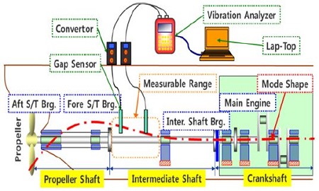
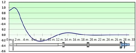
Although vibration measuring point is normally recommended at more apparent section of shafting system, it is only ideal approach since the highest amplitude of whirling is occurred in way of center of gravity of propeller. Hence optimal location of gap-sensor needs to define considering measurable range and measurement place. To define the optimal location, the mode shape of whirling vibration shall be investigated first of all. As shown in Figure 1, the red short dash line is the first mode shape and the gap sensor can be installed at aft part of intermediate shaft considering amplitude ratio.
2.2 Measurement Analysis System
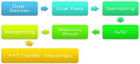
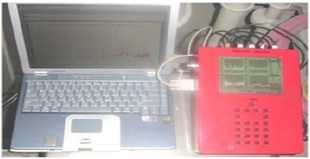
Measurement system is composed of gap-sensors, A/D convertor, vibration analyzer, etc as Figure 1 and the system flow chart is illustrated simply in Figure 2. Gap-sensor detects vertical distance deviation by shafting rotation and vibration analyzer assesses resonance frequency by order tracking using time delay of transferred signal to the sensor. In whirling vibration measurement using at least two gap-sensors is recommended to secure reproducibility of measured signal and to avoid measurement error.
3. Applications to Vessel for Comparison on Analysis and Measurement
Before carrying out measurement the whirling vibration analysis theoretically is conducted and after that the measurement is carried out based on the analysis results such as natural frequency and vibration mode shape. Based on these research results, much more accurate ways for assessment of natural frequency of whirling vibration is suggested in this chapter.
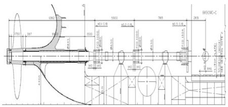
The vessel information applied to comparison on analysis results and measurement results is Table 1 and Figure 3 shows a general arrangement of the vessel shafting system.
3.1 Results of Whirling Vibration Analysis
Theoretical analysis of whirling vibration uses Jeon’s program [4][5] which is based on the Jasper theory by using transfer matrix method. As shown in Figure 3 the propulsion shafting system is quite complicated hence the shafting system needs to use simplified modelling such as Table 2. Although the Table 2 is simplified the analysis results is almost same as before and the deviation of analysis results is ignorable. In the simplified modelling the crankshaft part is omitted however the moment of inertia and mass of turning wheel is considered since the factors are affected to whirling vibration.
In the analysis, the propeller added mass theory which is Table 3 due to entrained water follows lows of Jasper and bearing stiffness including oil film, bearing and pedestal follows general recommended range refer to Table 4.
The analyzed natural frequency of whirling vibration is shown in Table 5.
3.2 Results of whirling vibration measurement
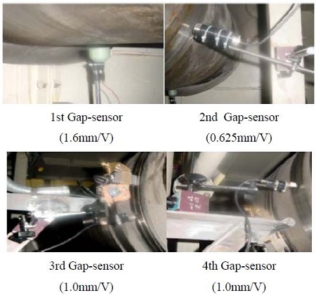
In order to reduce failure ratio for measurement total four gap-sensors are installed to in way of aft side of intermediate shaft since the part is bigger amplitude as shown in Figure 4 and the location is applicable this whirling vibration measurement. Figure 4 is gap-sensors installed on board and Figure 5 is vibration analyzer to analysis measured signal.
Instrumentation of Measuring Equipment
- 1) Displacement Sensor : 1.6mm/V 1set
0.625mm/V 1set
1.0mm/V 2sets - 2) Tachometer : 1 pulse/rev
- 3) Analyzer : Wartsila AA8
- 4) Program : WinVa supported by Wartsila
Measuring Procedure
- 1) Measurements are normally done within a sweep of the engine. A sweep is a steady raise of the engine from slow speed up to full speed. With the values measured and recorded during the sweep, Engineer is able to evaluate and recalculate the torsional vibration.
- 2) Standard values for speed increase
- Normal speed range : 2 rpm / 1 min
- Measurement time : twice (Increasing & decreasing rpm)
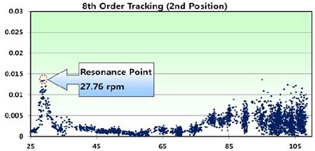
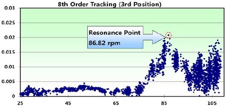
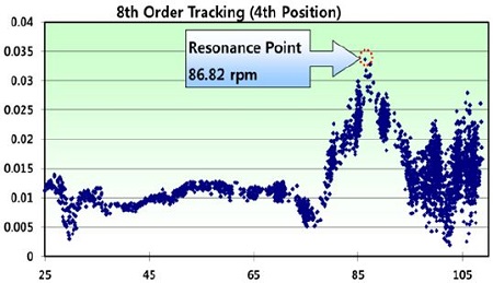
The results of whirling vibration is shown as order tracking plot which is that the horizontal axis is operating rpm and the vertical axis is displacement (mm). The displacement data measured by gap-sensors is too small to detect as a whole. However one resonance frequency, 86.82 rpm is 8th order component found in synthesis signal measured at 3rd and 4th gap-sensors.
1) 1st Gap-sensor
The sensor installed to flange casing is affected by noise occurred local vibration at flange casing, as a result, no order signal is detected in 1st sensor.
2) 2nd Gap-sensor
In Figure 7, there is one resonance point, 27.76 rpm at the 8th order tracking signal and the resonance point is not component of whirling vibration. The resonance point is progress by torsional vibration and the main resonance of torsional vibration is located at 28rpm. The gap sensor is installed at the position of 120 mm fore edge of the aft flange on the intermediate shaft.
3) 3rd Gap-sensor
In Figure 8, the measured resonance point is found as 86.82 rpm though the detected distance is very low and the gap sensor is installed at the position of 250 mm fore edge of the aft flange on the intermediate shaft.
4) 4th Gap-sensor
In Figure 9, the measured resonance point is found as 86.82 rpm though the detected distance is very low and the gap sensor is installed at the position of 260 mm fore edge of the aft flange on the intermediate shaft.
Main concerns are whirling vibration is natural frequency and dynamic behavior due to propeller and these are mainly occurred in 1st mode shape of whirling and the blade order of whirling vibration is main criteria in propulsion shafting system.
An example of blade order is 1st natural frequency divided by blade number, i.e., if the calculated 1st natural frequency is 400 cpm and blade number is 4 then the blade order frequency is calculated as 100 cpm.
In Section 3.2.2 the measured whirling resonance is 86.62 rpm at 8th order and based on the results the 1st natural frequency is assessed at 694.46 cpm. Furthermore using the assessed 1st natural frequency the blade order which is 5th order of whirling can be calculated and the 5th order is 138.91 cpm.
Finally deviation between analysis results and the measurement results using the assessed 5th order is confirmed as Table 6. Therefore this research has confirmed that the natural frequency of whirling vibration is able to measure as sweep test though the measuring range does not reach to target rpm, blade order.
4. Conclusions
Whirling vibration analysis of propulsion shafting system is carried out generally to make sure that the concerned natural frequency of whirling keeps a margin more than 20% compared to continuous operation rpm, MCR. Because making an accurate estimate regarding propeller induced excitation force is very difficult and in order to assess the excitation force shall be considered in many of factors such calculable and incalculable.
To verify the rotor vibration such as torsional, axial normally sweep test is used and the measurement method is limited for whirling vibration because the method is only available within operating rpm range. Hence whirling vibration requires other measurement to verify the natural frequency.
In this study assessment method of natural frequency of whirling vibration is suggested that the measured harmonic order component is used instead of target frequency which is blade order based on the sweep test within operating rpm range in 3.2.2. The results of the research are summarized below.
1) Since propeller induced excitation force due to propeller design property is difficult to define, calculating natural frequency of whirling vibration and mode shape are studied.
2) It is confirmed that the results of analyzed natural frequency nearly correspond with assessed measurement results.
3) It is eventually considered that the deviation between analyzed results and measured results is able to resolve by investigation regarding application of effect of entrained water of propeller and stiffness including oil film, pedestal of stern tube bearing.
4) The suggested assessment method of relevant natural frequency of whirling vibration is listed below.
i. Characteristics of whirling vibration are figured out based on theoretical background.
ii. Whirling vibration measurement using sweep test is carried out from minimum rpm to continuous operation rpm, MCR. (Standard values for speed increase are recommended as 2 rpm/min)
iii. Major natural frequency is calculated using measured harmonic order component of whirling vibration.
| (1) |
iv. Based on the assessed major natural frequency, the relevant blade order is calculated and confirmed that the blade order is out of continuous operating rpm according to relevant criteria.
| (2) |
Acknowledgments
This research is financially supported by Korea Ministry of Oceans and Fisheries (Development of OWC Wave Energy Utilization System). All the support is gratefully acknowledged.
This paper is extended and updated from the short version that appeared in the Proceedings of the International Symposium on Marine Engineering and Technology (ISMT 2014), held at BEXCO, Busan, Korea on October 17-19, 2014.
References
- E. Panagopulos, “Design-Stage Calculations of Torsional, Axial and Lateral Vibrations of Marine Shafting,”, Transactions of Society of Naval Architects and Marine Engineers, 58, p329-384, (1950).
- N. H. Jasper, A Theoretical Approach to the Problem of Critical Whirling Speeds of Shaft-Disk Systems, DTMB Report 890, David Taylor Model Basin Washington D. C., America, (1954).
- N. H. Jasper, A Design Approach to the Problem of Critical Whirling Speeds of Shaft-Disk Systems, DTMB Report 890, David Taylor Model Basin Washington D. C., America, (1954).
- H. J. Jeon, Whirling Vibration Problem for Propulsion Shafting System, Korea Ship Safety Technology Authority Report, 7th Edition, Korea Maritime & Ocean University, Korea, (2001).
- H. J. Jeon, Ship Propulsion Transmission Equipment, Taehwa Publishing Company, (1986).

