A study on performances of SOFC integrated system for hydrogen-fueled vessel
Copyright © The Korean Society of Marine Engineering
This is an Open Access article distributed under the terms of the Creative Commons Attribution Non-Commercial License (http://creativecommons.org/licenses/by-nc/3.0), which permits unrestricted non-commercial use, distribution, and reproduction in any medium, provided the original work is properly cited.
Abstract
Hydrogen is a bright future energy carrier with high energy content and an environmentally friendly, sustainable source of energy for end-use. Regarding maritime applications, hydrogen can be utilized in fuel cells. Researchers have recognized the solid oxide fuel cell (SOFC) for converting the chemical energy of hydrogen into electricity at a better efficiency than previous technologies. The SOFC has a high working temperature of 700°C to 900°C and is easy to combine with the waste heat recovery cycles to increase output power and thermodynamic performances as well. In this work, the conceptual design of a hydrogen supply system for SOFC combined with an Organic Rankine Cycle (ORC) and a refrigeration system is proposed and presented. The designation is aimed to target training ships that use electric propulsion. The integrated system's energy and exergy efficiencies are 66.56% and 56.8%, respectively. The ORC's energy and exergy efficiencies are 10.11% and 15.31%, respectively. The parametric analysis revealed that the ORC's turbine input temperature, current density, fuel utilization factor, and are the main factors influencing system performance.
Keywords:
Liquefied hydrogen, SOFC, Waste heat recovery, Cold energy, Refrigeration system1. Introduction
In Resolution MEPC.304 (72) of the Marine Environmental Protection Committee (MEPC) adopted in April 2018, the International Maritime Organization (IMO) set high goals for decarbonizing the world fleet. Targets outlined in the IMO initial strategy are to reduce at least a 40% in average carbon dioxide (CO2) emissions per transport work from 2008 levels by 2030 and a 70% reduction by 2050. By 2050, these goals also aim to cut the total yearly greenhouse gas (GHG) emissions from shipping by at least 50%. There are several methods under consideration to lower shipping's carbon footprint. The IMO GHG reduction objective for 2050 can be achieved by using low- to non-carbon fuels, one of which is hydrogen (liquefied H2 –LH2 or gaseous H2-GH2).
Being the most prevalent element in the universe, hydrogen possesses the highest energy efficiency and ecologically benefit. In nature, hydrogen is frequently found in mixtures with either methane or water. To achieve pure hydrogen, the compounds must be taken out. Under atmospheric conditions, hydrogen is a colorless, odorless, tasteless, harmless gas with a wide range of flammability that is also largely non-reactive. With the top energy content per mass of 120.2 MJ/kg, hydrogen performed as the chemical fuel with the greatest performance when compared to other marine fuels. Its mass energy is 2.8 times more than that of marine gasoil and 5–6 times greater than that of methanol. Hydrogen fuel can thereby increase an engine's real efficiency and assist reduce specific fuel usage [1]. The density of hydrogen in liquid or cryogenic form is significantly higher than the density of hydrogen in gasoline. As a result, the volumetric energy density increases significantly. According to J. O. Abe et al.,[2], liquid hydrogen can have a density of about 71 g/L at -253°C, which corresponds to 8 MJ/L H2 in terms of energy density [3][4]. Liquid hydrogen has no corrosive properties. Stainless steel and aluminum alloys with enough insulation are excellent materials for cryogenic storage because of this property of the fluid. At atmospheric pressure, hydrogen exists as a liquid at -253°C (-423°F). Contact with materials at this low temperature can cause frostbite and cryogenic burns. Personal protective equipment (PPE) to protect against accidental exposure is needed. In addition, fuel used in the system is kept insolated to the surroundings by tank and pipelines to eliminate the dangers of low temperature LH2.
Fuel cells are an innovative and practical approach to decarbonizing the maritime sector. Depending on their operating temperature and electrolyte, several fuel cell types are available for use, such as solid oxide fuel cells (SOFC), alkaline fuel cells (AFC), proton exchange membrane fuel cells (PEMFC), and phosphoric acid fuel cells (PAFC). The SOFC appears to be the fuel cell that is best suited to use hydrogen for marine vessels [5] because (i) energy and heat from SOFCs can be recovered, reused, and used in other cycles to increase the system's overall energy and efficiency [6]; (ii) the SOFCs are highly durable, and their high power energy makes them more appropriate for ship applications. As a result, manufacturers and researchers paid more attention to the hydrogen SOFC system.
Recent attention has been paid to liquefied hydrogen cold energy utilization. Liquefied hydrogen is pre-heated to the appropriate temperature before being fed to the anode side of the SOFC because it is often kept at a very low temperature (-253°C) under atmospheric pressure. If the cold energy is released to the sea water during pre-heating process, it will be regarded as waste heat (waste of thermal energy). Onboard hydrogen supply systems for SOFC were proposed by Yang targeted for heavy-duty hybrid trucks [7]. The cold energy from liquid hydrogen (LH2) was utilized in the adsorption cycles, which also contain a heater, two heat exchangers, and a pump before being supplied to SOFC. The cold energy of LH2 in the evaporation process is directly used for cooling the input air of the compressor and the coolant of the accessories cooling system using a vaporizer to decrease used power, such as the power needed by the air compressor, water pump, and radiator fan. When compared to the prior LH2 system without cold energy usage, the new technology may result in power savings when the ambient temperature was 25°C. The most power that could be saved was 1.8 kW or about 15% of the total power. The intercooler heat load may also be decreased, which has the added benefit of making the intercooler smaller. A unique integrated hydrogen liquefaction system using SOFC, and cold energy-recovering photovoltaic panels was proposed by Taghavi et al., [8]. This integrated structure generates 1,028 kg/h of liquid hydrogen in Yazd's climatic conditions by ingesting 60.79 kg/h of natural gas and 5.559 MW of electricity from solar panels. The specific energy consumption and the efficiency of the SOFC are 5.955 kWh/kg LH2, 62.96%, respectively. The efficiency of the cycle for producing power from carbon dioxide are calculated to be 44.06%. To connect the refrigeration structure, hot and cold composite diagrams were employed. The most exergy destruction is seen in solar panels (81.37%), heat exchangers (7.60%), and turbines (4.73%), according to the exergy evaluation.
Additionally, researchers and manufacturers are paying close attention to the waste heat recovery from hydrogen SOFC. The integrated SOFC system for marine vessels was suggested by Duong et al., as the intended application [9]. According to the study, the exergy and energy efficiencies of the system may be increased by combining the gas turbine (GT), steam Rankine cycle (SRC), and exhaust gas boiler (EGB) as waste heat recovery cycles of SOFC. The combined cycles increased energy efficiency by 10.57% as compared to a SOFC stand-alone system and produced 1020.6 kW more output power, which went into the propulsion plant's overall power generation. The SOFC combine heat, hydrogen, and power system at small-scale application objectives were created and investigated by Perna et al., [10]. The combined heat, hydrogen and power (CHHP) plant's capacity to create 100 kg of hydrogen per day was a crucial need in order to supply small-scale hydrogen refueling stations. Two different design concepts that differ in terms of the size and functionality of the power generating portion have been considered.
According to the aforementioned literature evaluations, researchers have studied and assessed the idea of a hydrogen supply system for SOFC with a number of system proposals. In addition to enhancing the system's power production, the integrated system also improves thermal efficiency. The integrated system must be chosen, nevertheless, with each individual target application and target design, taking into account accessibility, cost, installation space, and operational friendliness. Regarding applications for small-scale vessels, the concepts include combining the use of cold energy from LH2 stored at -253°C and 1atm with the recovery of waste heat from the SOFC exhaust stream, which typically ranges from 700°C to 1000 °C. The new integrated system possesses three outstanding characteristics:
- • Firstly, the proposed system is targeted for small-scale power generation vessel which consume hydrogen as fuel.
- • Secondly, integrating the bottoming cycles (ORC and GT) will result in a higher system efficiency by using the waste heat recovery from SOFC.
- • Thirdly, hydrogen is used in the proposed SOFC-GT-ORC unified power system as the heat sink for refrigeration system and ORC and finally supply fuel for the SOFC.
In this work, energy and exergy studies are used as the main research approaches to examine an integrated power system. The integrated power system is introduced first, followed by a discussion of the key simulation ideas. Results of the simulation, an examination of the exergy, and parametric study are depicted and analyzed.
2. System description
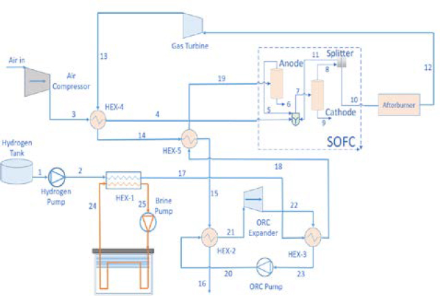
The suggested system is designed for an existing training ship of Vietnam Maritime University named Sao Bien (Figure 1). The detail parameters of the training ship are list in Table 1 [11]. The author’s purpose is to design a new system that utilizes a hydrogen-powered electric propulsion system (520kW). The power generated from SOFCs is used for the main propulsion system, and the auxiliary machinery and lighting system utilized power generated by a GT and an SRC. The planned multiple-generation system is made up of three primary components: (i) a SOFC technology that produces the majority of the power, (ii) a refrigeration system that uses liquefied hydrogen, and (iii) waste heat that is recovered through bottoming cycle. Figure 1 shows the proposed system's schematic.
Refrigeration system: Liquefied hydrogen (1) is initially pumped to required pressure, and then preheated by the condenser (HEX-1) in the refrigeration system. At this stage, the cold energy of liquefied hydrogen is used as the cold source of the condenser in the system. In this work, a brine refrigerant-based indirect refrigeration system was employed to exploit LH2 cold energy. In heat exchange number 1 (HEX-1), the LH2's temperature dropped as heat was transferred from the working fluid of the refrigeration system to it. The indirect refrigeration system has the benefits of being straightforward, compact, simple to maintain, and having minimal investment costs as compared to a direct cooling system. Furthermore, since there is no chance of leaking during the compression and expansion operations, food products keep their freshness longer and are more stable in the refrigerator. High specific heat, low specific gravity, low viscosity, and low freezing point should all be characteristics of brine refrigerants used in refrigeration systems. Ethyl alcohol, a brine refrigerant frequently utilized in settings with temperatures below -50 °C, was selected for this investigation.
ORC: Organic Rankine Cycle is installed using the cold energy of LH2 as cold source and recover waste heat from SOFC-GT system as hot source. The hydrogen gas is preheated through heat exchanger 3 (HEX-3) of the ORC and then heat exchanger 5 before supplied to SOFC system. Different working fluids includes toluene, cyclohexane, R123, R601, and R141b are analyzed to find the best matching working fluid for the system. Among them, R141b presents best performance to be a proper refrigerant of the ORC.
SOFC: After the refrigeration and ORC, hydrogen is continuously heated through heat exchanger 5 (HEX-5) before being supplied to the anode side of the SOFC. HEX-5 is necessary for the fuel cell to accomplish its required operational temperature which ranges from 700-900°C. After being compressed by an air compressor to attain the expected pressure, air receives waste heat from the gas turbine to reach the suitable temperature before being fed to the cathode side of SOFC. Input air (Oxygen), hydrogen, and a part of unreacted hydrogen returning back from the splitter are mixed before all the components are fed to SOFC. The splitter ensures the complete reaction of hydrogen as fuel in SOFC to generate maximum electricity. The electrochemical reaction will take place in the fuel cell to generate power.
Afterburner - Gas turbine: After reacting in the fuel cells, two exhaust streams are generated. The foremost stream is provided to the afterburner. Otherwise, the exhaust of water and remaining oxygen from the cathode is discharged. The afterburner burns the unused hydrogen and oxygen to produce high-pressure, high-temperature exhaust gas. This exhaust gas is then supplied to the turbine to generate more electricity. Then, the exhaust gas enters through heat exchanger four (HEX-4) and heat exchanger five (HEX-5) sequentially to heat the supplied air and hydrogen to support them to gain the operating temperature of SOFC. Then this exhaust gas is discharged into the environment.
3. Material and methodology
3.1 Operating data performances and assumptions
With assistance from ASPEN-HYSYS V12.1 (Aspen Tech, Massachusetts, USA), the author simulated the integrated SOFC system that utilize hydrogen as a direct fuel. Chemical and physical characteristics of heterogeneous mixtures at various operating pressures and temperatures are provided by comprehensive thermodynamic databases of the Aspen-HYSYS program with a single fluid package. With the help of this chemical process simulator, it is possible to simulate complicated processes with several streams. Aspen HYSYS defines hydrogen as the pure component; as a result, all components' thermodynamic characteristics and operational parameters are estimated using the Peng-Robinson (PR) equations of state.
The common assumptions listed below are used to simplify models and analysis:
- • This simulation is carried out in a thermodynamic equilibrium and steady state;
- • All pipe have negligible pressure losses;
- • At 29.85 C, and 101.3 kPa, the supplied air is composed of N2 at 79% and O2 at 21% in molecular;
- • It is assumed that the pressure losses on the shell and tube sides of the heat exchanger (HEX) are 6.895 and 3.447 kPa, respectively [9];
- • At the SOFC's input and output, the temperature of the air and fuel flowing through them is constant and the same as the SOFC's operating temperature.
Table 2 contains a list of the simulation study's boundary conditions [9][12].
3.2 SOFC model
The chemical and thermodynamic relationships between system components are used in the system modeling process and are explicated for each sub-system. In SOFCs, the fuel's chemical energy is converted into electricity. The cathode produces oxygen ions and these ions move across a membrane to the anode. Electrical current is produced as a result of the anode-created electrons moving into the cathode after crossing an external circuit [13]. Accordingly, the cathode and anode undergo the following electrochemical processes:
| (1) |
| (2) |
The total reaction can be given:
| (3) |
Typically, the cell is supplied with more hydrogen than is necessary for the process in order to decrease polarization losses caused by hydrogen concentration at the electrode. Utilization of fuel (hydrogen) is defined as following [14]:
| (4) |
Where hydrogen react and hydrogen input stand for the molar flow of hydrogen that is reacting and the molar flow of hydrogen that is given to the fuel cells, respectively.
Since air is assumed to have a constant mixture of 21% oxygen and 79% nitrogen in molecular, the air utilization may also be calculated as the ratio of oxygen supply to usage:
| (5) |
Air in (kg/h) is the molar flow of the inlet air.
The oxygen molar flow rate can be identified as follow:
| (6) |
The molar flow rates of oxygen and hydrogen needed for the fuel cells, respectively, are represented by the numbers nO2 and nH2.
The component stack may be used to calculate the net power output of a SOFC system, as follow [15]:
| (7) |
Where a is the surface area (m2), i is the current density (A/m2), and Vc is the actual voltage of the stack (V).
| (8) |
| (9) |
Where n is the number of electrons that are transferred by each oxygen atom during the electrochemical process, which in this instance equals 2; qH2 is the hydrogen molar flow rate (mol/s); F stands for the Faraday constant, 96,485 C/mol; Ncell and A cell stand for the number of cells and cell area (m2), respectively.
The I-V curve is used to calculate the stack's actual voltage [10][12][16].
| (10) |
The energy efficiency of the fuel cell can be calculated as following:
| (11) |
Where mH2 and LHVH2 stand for the low heating value of H2 (KJ/kg) and the mass flow rate of H2 (kg/h), respectively.
3.3 Refrigeration system model
The proposed system is designed for a training ship equipped with one refrigeration warehouse with a total food gross tonnage of 3000 kg. The conditions preparing for the brine refrigerants should be large specific heat, have low viscosity, specific gravity, freezing point, and low corrosion resistance to metal. In this study, referring to the study of Ryu Bo Rim and his research group, the brine refrigerant for cooling the freezer of hydrogen fuel-powered refrigeration carrier was selected as ethyl alcohol (C2H5OH) [17].
The brine flow rate (Q) for transporting the freezing reservoir of about -13˚C to the unloading area with a total food gross tonnage of 3000 kg at -18˚C can be calculated due to the total cold heat required for cooling the freezer, the temperature change of the working fluid, the density and specific heat of the working fluid, as shown in the following equation:
| (12) |
The amount of frozen heat to ship 1kg of food rapidly cooled to about -13˚C and maintain it at about -18˚C can be computed as below:
| (13) |
The total amount of cold heat required for the cargo tank to transfer freezing reservoirs of about -13˚C to the unloading area can be determined in ft3 by the volume of one ton of frozen food when loading cargo in the cargo warehouse. Considering that the average food specific heat is 0.85 kcal/kg˚C (meet, vegetables and fruits) [27], it is calculated in Table 3:
The total amount of cold heat required is about 531.25 kcal/h, the density and the specific heat of ethyl alcohol is 789(kg/m3) and 0.5(kcal/kg˚C), respectively. The flow rate of the brine refrigerant is calculated to be 0.03367(m3/h) when discharged from the heat exchanger at a brine inlet temperature of -2˚C and out let temperature of -30˚C.
3.4 ORC model
The formula for the ORC turbines' energy balance is:
| (14) |
The ORC's HEX-2's absorption of waste heat:
| (15) |
The ORC power output can be calculated as following:
| (16) |
The energy and exergy efficiency of the ORC can be given:
| (17) |
| (18) |
3.5 Gas turbine model
Once the hot gaseous mixture leaves the combustion chamber and reaches the gas turbine, it expands and generates usable mechanical power. The SOFC-GT subsystem energy efficiency can be calculated as:
| (19) |
Exergy efficiency is determined as:
| (20) |
3.6 System energy and exergy efficiency
The system's exergy serves as a visual representation of the maximum amount of operating capacity that was lost during the process. The second law of thermodynamics is applied to calculate the energy efficiency of the main parts of the system. The total energy and energy efficiency of the integrated system are displayed as [9][18]:
| (21) |
Where Welec,overall denotes the overall net value of the system's power generation and consumption:
| (22) |
LHVhydrogen is the lower heating value of hydrogen (kJ/kg).
According to the second law of thermodynamics, the total exergy is equal to the sum of the chemical, physical, potential, and kinetic exergy. The potential and kinetic exergy are minimal in this study. The exergy efficiency of the system is given as below:
| (24) |
4. Results and discission
4.1 Energy and exergy efficiency of the system
Thermodynamic characteristics and state points for each node of the proposed integrated power system are listed in Table 4.
Table 5 provides information on the performance of the system's key parts. The results show that recovering the SOFC-GT exhaust gas via the ORC increased the proposed system's total electrical efficiency to about 66.56%. Parameter adjustment can lead to additional gains.
The target ship needs 520 kW of electricity for its primary propulsion system, plus more for auxiliary equipment, lighting, and crew needs. While maintaining a suitable reactant concentration and fuel cell efficiency, the fuel cell should be run at its optimum fuel usage factor. The SOFC's energy efficiency is 50.71% for a utilization factor of 0.95. According to the thermodynamic models created in Section 3, the combined output power of the integrated system is 682.458 kW, which is sufficient to run the vessel and its auxiliary systems. The power generated from waste heat recovery bottoming cycles, which account for nearly all of the 217.13 kW excess above the ship's power need (about 31.9% of total electrical output), show that the subsystem was essential for the operation of auxiliary systems. The suggested system has total energy and exergy efficiency of 66.56% and 56.8%, respectively. Table 6 includes the whole system's energy and exergy efficiencies as well as those of each subsystem.
Compared to the same developed designation that applies fuel cells technology for propulsion plant, the novel SOFC-GT-ORC integrated system achieved acceptable results. Duong et al., proposed such system that uses ammonia as fuel. Their system gained 60.4% energy efficiency and 57.3% exergy efficiency of the total system [28]. On the other hand, when LNG is used as fuel of the system, researchers found that the system could achieve better performance in energy efficiency. Xiaoyu Yang et al., suggested a LNG-fueled SOFC integrated system which possessed 79.14% in energy efficiency [29]. This high result is due to the surplus of about 15% in energy efficiency by including the energy for the fuel preheating process, which is not considered in our research.
4.2 ORC working fluid selection
Organic Rankine Cycle utilizes the waste heat from SOFC as hot source and LH2 as cold source. The choice of working fluids has a significant impact on the ORC system's performance and economics since it influences the system's efficiency, component sizes, expansion machine design, stability, safety, and environmental considerations [19][20][21]. There are two key factors that make choosing the working fluid for ORC systems more challenging than choosing the working fluid for other thermodynamic cycles like the compression refrigeration cycle and the Kalina cycle (working fluid composition is set although mass fractions vary).
There are many different working environments and heat source types for ORC, ranging from low-temperature heat sources of 80°C (such as geothermal and plate-type solar collectors) to high-temperature heat sources of 500°C (e. g. biomass); Hundreds of substances, such as hydrocarbons, aromatic hydrocarbons, CFCs, alcohols, ethers, and siloxanes, etc., can be used as working fluid candidates of ORC, with the exception of some substances whose critical temperatures are too low or high.
Bao and his research group found that with the range of heat source greater than 202°C, R123, R601, and R141b can be chosen to be suitable working fluid for ORC [22]. Moreover, cyclohexane and toluene, which have high critical temperature present a good thermal match with high-temperature heat source [23]. In this study, the above-mentioned working fluid are applied and analyzed to find the best match for the requirement of ORC.
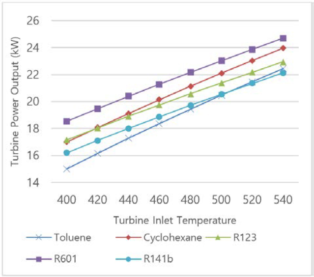
The intake temperature of the exhaust gas is set and assumed to be a constant value of 540°C in order to examine the influence of the turbine inlet temperature. Figure 3 show the variation of the ORC turbine power output with the turbine inlet temperature. As turbine inlet temperature increases, the turbine power output for all working fluids increases since the greater pressure at the turbine intake caused by higher temperature. Similarly, at the same turbine inlet temperature, R601 shows the highest turbine inlet power output.
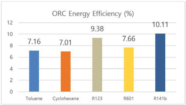
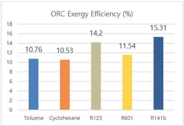
Figure 4 and Figure 5 shows the exergy and energy efficiency of organic Rankine cycle. For both efficiencies, R141b presents the best performance of 10.11% and 15.31%, respectively. Though the turbine power out of this refrigerant is lower than that of other analyzed working fluid (as shown in Figure 2), the difference is smaller than 5 kW, which is a negligible quantity compared to overall system power output. Furthermore, R141b satisfies environmental friendly requirements with Global Warming Potential (GWP) of 700 and Ozone Depletion Potential (ODP) of 0.086 [26]. Due to these reasons, R141b is chosen to be the proper working fluid in this study.
4.3 Influence of the key parameters on the system’s performance
To gauge the integrated system's overall performance, a parametric analysis based on the first and second laws of thermodynamics was carried out. Performance of the combined SOFC-GT-ORC system is affected by many factors. Although estimating the waste-heat recovery of the SOFC-GT system utilizing ORC to deliver electricity to the target vessels' propulsion plants and other auxiliary electrical equipment is the study's main objective, it is secondary to that objective. A refrigeration system for storing frozen food is one of the secondary system outputs.
The parametric research looked at how changing the fuel utilization factor, current density and turbine inlet temperature influenced the system's overall energy and energy efficiency.
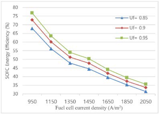
With fuel utilization factors (Uf) of 85%, 90%, and 95%, respectively, the performance of the SOFC system has been investigated. Figure 5 illustrates how Uf influences the SOFC and integrated system's performance. It is demonstrated that system efficiency increases with fuel utilization ratio when the concentration polarization is not noticeably bigger than other polarizations. When cells run at low current densities, the influence of the fuel usage ratio becomes significant. The energy efficiency of the combined cycle increases when the SOFC-GT operates at lower current densities. This is because the output power declines more quickly than the mass flow rate of the fuel entering the system. The findings of the thermodynamic modeling reported in the references concur with the computed values for the SOFC-energy GT's efficiency [24][25].
The system's energy efficiency reaches its peak value with the Uf value of 0.95. This is due to the SOFC stack's increased hydrogen consumption as the Uf is raised, which simultaneously raises the current density and lowers the voltage due to internal irreversibility. Moreover, Lowering the SOFC and afterburner outlet temperatures also reduces the GT's intake temperature and power output.
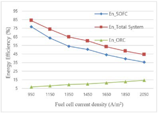
The current density is one of the most crucial performance metrics for the fuel cells and the entire system. Figure 6 illustrates how the system's and other significant components' energy efficiency is impacted by the current density. Densities at the moment range from 950 A/m2 to 2050 A/m2. The working pressure and temperature of the cell are 4 bar and 803.2 °C, respectively. It can be shown that while the energy efficiency of the ORC slightly rises with an increasing in current density. The energy efficiency of the SOFC-GT subsystem and the total system declines as current density increases.
The net electrical cycle efficiency ranges from 44.4% at 2050 A/m2 to 83.9% at 950 A/m2. With an increase in current density, the SOFC system's energy efficiency decreases. Due to the higher current density, more oxygen ions must be supplied by increasing air flow. Moreover, the gain in chemical energy that results from reduced efficiency generates heat that needs to be expelled at the air intake in order to maintain the cells' working temperature. Efficiency is higher while operating at low current densities. More capital (more cells) are required for low-current-density operation to generate the same quantity of power as high-current-density operation.
4. Conclusion
The system's energy and exergy performances were assessed using the first and second laws of thermodynamics. The first law assesses electrical efficiency, power, power density, current density, voltage, and exergy efficiency; the second law assesses exergy losses and exergy efficiency.
In the current work, waste heat from a SOFC system is recovered using an ORC and a GT. An increase in power of 98.617 kW was forecast by a thermodynamic analysis as a result of the ORC and GT. The ORC presents performance with energy and exergy efficiency of 10.11% and 15.31%, respectively. An indirect refrigeration system is installed to utilize the cold energy from LH2 to store freezing food as the ship’s cargo.
Moreover, a parametric analysis revealed that the ORC's turbine input temperature, current density, fuel utilization factor, and are the main factors influencing system performance. Further conclusions include:
- • As turbine inlet temperature increases, the ORC turbine power output for all working fluids increases since the greater pressure at the turbine intake caused by higher temperature.
- • For ORC, R141b is chosen to be the proper working fluid for its highest energy efficiency, exergy efficiency, and environmental friendly satisfaction.
- • Because of the SOFC's higher fuel consumption, the energy efficiency of the cycle drops as the current density rises. When efficiency falls, more unconverted chemical energy is converted into heat, which raises the need for inlet air cooling to keep the modules' operating temperature constant.
- • The efficiency of the system rises as the fuel utilization factor rises. The hybrid system's and combined cycles' energy efficiency is optimum within the testing range at the Uf value of 0.95. On the other hand, when the fuel utilization factor rises, the cycles' net output power drops.
Combination cycles provide higher energy efficiency as compared to the SOFC stand-alone system, which encourages the implementation of the proposed combination cycles.
Acknowledgments
This research was supported by Korea Institute of Marine Science & Technology Promotion (KIMST) funded by the Ministry of Oceans and Fisheries, Korea (20200520).
Author Contributions
Formal analysis, Q. H. NGUYEN; Investigation, P. A. DUONG, B. R. RYU; Methodology, Q. H. NGUYEN; Supervision, H. K. KANG; Writing—original draft, Q. H. NGUYEN; Writing—review and editing, P. A. DUONG; H. K. KANG. All authors have read and agreed to the published version of the manuscript.
References
- ABS, Hydrogen as Marine Fuel Whitepaper, https://absinfo.eagle.org/acton/media/16130/hydrogen-as-marine-fuel-whitepaper, , Accessed February 28, 2023.
-
J. O. Abe, A. P. I. Popoola, E. Ajenifuja, and O. M. Popoola, “Hydrogen energy, economy and storage: Review and recommendation, International Journal of Hydrogen Energy,” vol. 44, no. 29, pp. 15072-15086, 2019.
[https://doi.org/10.1016/j.ijhydene.2019.04.068]

-
D. J. Durbin and C. Malardier-Jugroot, “Review of hydrogen storage techniques for on board vehicle applications,” International Journal of Hydrogen Energy, vol. 38, no. 34, pp. 14595-14617, 2013.
[https://doi.org/10.1016/j.ijhydene.2013.07.058]

-
H. Barthelemy, W. Weber, and F. Barbier, “Hydrogen storage: Recent improvements and industrial perspectives,” International Journal of Hydrogen Energy, vol. 42, no. 11, pp. 7254-7262, 2017.
[https://doi.org/10.1016/j.ijhydene.2016.03.178]

-
O. Siddiqui and I. Dincer, “Analysis and performance assessment of a new solar-based multigeneration system integrated with ammonia fuel cell and solid oxide fuel cell-gas turbine combined cycle, Journal of Power Sources, vol. 370, pp. 138-154, 2017.
[https://doi.org/10.1016/j.jpowsour.2017.10.008]

-
A. Perna, M. Minutillo, E. Jannelli, V. Cigolotti, S. W. Nam, J. Han, “Design and performance assessment of a combined heat, hydrogen and power (CHHP) system based on ammonia-fueled SOFC,” Applied Energy, vol. 231, pp. 1216-1229, 2018.
[https://doi.org/10.1016/j.apenergy.2018.09.138]

-
M. Yang, S. Hu, F. Yang, L. Xu, Y. Bu, and D. Yuan, “On-board liquid hydrogen cold energy utilization system for a heavy-duty fuel cell hybrid truck,” World Electric Vehicle Journal, vol. 12, no. 3, p. 136, 2021.
[https://doi.org/10.3390/wevj12030136]

-
M. Taghavi, H. Salarian, and B. Ghorbani, “Thermodynamic and exergy evaluation of a novel integrated hydrogen liquefaction structure using liquid air cold energy recovery, solid oxide fuel cell and photovoltaic panels,” Journal of Cleaner Production, vol. 320, 128821, 2021.
[https://doi.org/10.1016/j.jclepro.2021.128821]

-
P. A. Duong, B. Ryu, C. Kim, J. Lee, and H. Kang, “Energy and exergy analysis of an ammonia fuel cell integrated system for marine vessels,” Energies, vol. 15, no. 9, pp. 1-22, 2022.
[https://doi.org/10.3390/en15093331]

-
A. Perna, M. Minutillo, E. Jannelli, V. Cigolotti, S. W. Nam, J. Han, “Design and performance assessment of a combined heat, hydrogen and power (CHHP) system based on ammonia- fueled SOFC,” Applied Energy, vol. 231, pp. 1216-1229, 2018.
[https://doi.org/10.1016/j.apenergy.2018.09.138]

- Tau huan luyen sao bien Dai Hoc Hang Hai Viet Nam, http://qttb.vimaru.edu.vn/tau-huan-luyen-sao-bien, , Accessed March15, 2023.
-
K. H. M. Al-Hamed and I. Dincer, “A novel ammonia solid oxide fuel cell-based powering system with on-board hydrogen production for clean locomotives,” Energy, vol. 220, 119771, 2021.
[https://doi.org/10.1016/j.energy.2021.119771]

-
M. Irshad, K. Siraj, R. Raza, A. Ali, P. Tiwari, B. Zhu, A. Rafique, A. Ali, M. K. Ullah, and A. Usman, “A brief description of high temperature solid oxide fuel cell’s operation, materials, design, fabrication technologies and performance,” Applied Sciences, vol. 6, no. 3, p. 75, 2016.
[https://doi.org/10.3390/app6030075]

-
G. Cinti, L. Barelli, and G. Bidini, “The use of ammonia as a fuel for transport: Integration with solid oxide fuel cells,” AIP Conference Proceedings, vol. 2191, no. 1, 020048, 2019.
[https://doi.org/10.1063/1.5138781]

-
M. Song, Y. Zhuang, L. Zhang, W. Li, J. Du, and S. Shen, “Thermodynamic performance assessment of SOFC-RC-KC system for multiple waste heat recovery,” Energy Conversion Management, vol. 245, 114579, 2021.
[https://doi.org/10.1016/j.enconman.2021.114579]

-
Q. Ma, R. Peng, L. Tian, and G. Meng, “Direct utilization of ammonia in intermediate-temperature solid oxide fuel cells,” Electrochemistry Communications, vol. 8, no. 11, pp. 1791-1795, 2006.
[https://doi.org/10.1016/j.elecom.2006.08.012]

-
B. Ryu, D. P. Anh, Y. H. Lee, and H. K. Kang, “Study on LNG cold energy recovery using combined refrigeration and ORC system: LNG-fueled refrigerated cargo carriers, Journal of Advanced Marine Engineering and Technology, vol. 45, no. 2, pp. 70-78, 2021.
[https://doi.org/10.5916/jamet.2021.45.2.70]

-
E. Gholamian and V. Zare, “A comparative thermodynamic investigation with environmental analysis of SOFC waste heat to power conversion employing Kalina and Organic Rankine Cycles,” Energy Conversion Management, vol. 117, pp. 150-161, 2016.
[https://doi.org/10.1016/j.enconman.2016.03.011]

-
S. Quoilin, S. Declaye, B. F. Tchanche, and V. Lemort, “Thermo-economic optimization of waste heat recovery Organic Rankine Cycles,” Applied Thermal Engineering, vol. 31, no. 14-15, pp. 2885-2893, 2011.
[https://doi.org/10.1016/j.applthermaleng.2011.05.014]

-
A. Stoppato, “Energetic and economic investigation of the operation management of an Organic Rankine Cycle cogeneration plant, Energy, vol. 41, no. 1, pp. 3-9, 2012.
[https://doi.org/10.1016/j.energy.2011.09.033]

-
A. Schuster, S. Karellas, E. Kakaras, and H. Spliethoff, “Energetic and economic investigation of Organic Rankine Cycle applications,” Applied Thermal Engineering, vol. 29, no. 8-9, pp. 1809-17, 2009.
[https://doi.org/10.1016/j.applthermaleng.2008.08.016]

-
J. Bao and L. Zhao, “A review of working fluid and expander selections for Organic Rankine Cycle, Renewable and Sustainable Energy Reviews, vol. 24, pp. 325-342, 2013.
[https://doi.org/10.1016/j.rser.2013.03.040]

-
H. Tuo, “Energy and exergy-based working fluid selection for organic Rankine cycle recovering waste heat from high temperature solid oxide fuel cell and gas turbine hybrid systems,” International Journal of Energy Research, vol. 37, no. 14, pp. 1831-1841, 2012.
[https://doi.org/10.1002/er.3001]

-
E. Baniasadi and I. Dincer, “Energy and exergy analyses of a combined ammonia-fed solid oxide fuel cell system for vehicular applications, International Journal of Hydrogen Energy, vol. 36, no. 17, pp. 11128-11136, 2011.
[https://doi.org/10.1016/j.ijhydene.2011.04.234]

-
M. Ni, D. Leung, and M. Leung, “Thermodynamic analysis of ammonia fed solid oxide fuel cells: Comparison between proton-conducting electrolyte and oxygen ion-conducting electrolyte, Journal of Power Sources, vol. 183, no. 2, pp. 682-686, 2008.
[https://doi.org/10.1016/j.jpowsour.2008.05.022]

- Rhodia, Chemicals Ltd. United Kingdom, Refrigerant Gases, HCFC, Briton Refrigerant R141B. https://www.rhodia-refrigerants.co.uk/refrigerant-gases/hcfc/briton-refrigerant-r141b-gas/, , Accessed March 18, 2023.
- The Engineering ToolBox, Food and Foodstuff, Specific heat, https://www.engineeringtoolbox.com/specific-heatcapacity-food-d_295.html, , Accessed February 22, 2023.
-
P. A. Duong, B. Ryu, J. Jung, and H. Hang, “Thermal evaluation of a novel integrated system based on solid oxide fuel cells and combined heat and power production using ammonia as fuel,” Applied Sciences, vol. 12, no. 12, 2022.
[https://doi.org/10.3390/app12126287]

-
X. Yang, H. Zhao, and Q. Hou, “Proposal and thermodynamic performance study of a novel LNG-fueled SOF-CHAT-CCHP system with near-zero CO2 emissions, International Journal of Hydrogen Energy, vol. 45, no. 38, pp. 19691-19706, 2020.
[https://doi.org/10.1016/j.ijhydene.2020.05.012]


